NEOTA NeoRe TG Series User manual

Installation manual
NeoRé TG
Heat pump air-water
NeoRé 5TG
NeoRé 8TG
NeoRé 11TG
NeoRé 14TG
NeoRé 8TG HP
NeoRé 11TG HP
NeoRé 14TG HP
NeoRé 16TG HP
All rights and changes reserved. Last update 03.07.2020 - 0.1.3

Contents
1 Introduction 4
2 Safety instructions 5
2.1 Safetywarning...................................................... 5
2.2 Safetyprecautions.................................................... 5
2.3 Legalconditions..................................................... 6
2.4 Storageandtransportconditions ........................................... 7
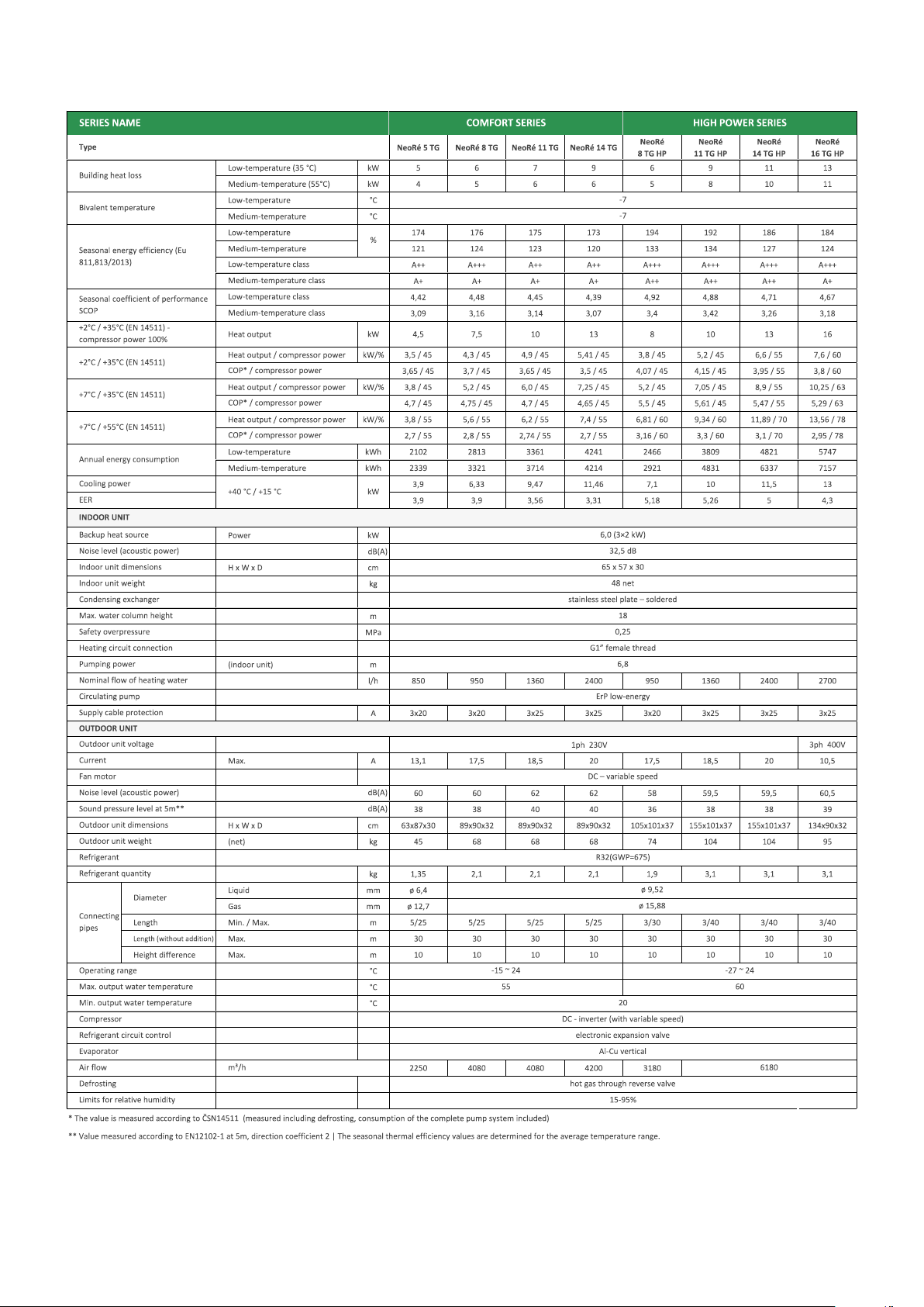
2.5 Tableoftechnicalparameters ............................................. 8
3 Installation manual 9
3.1 Workingconditions ................................................... 9
3.1.1 Workingenvironment.............................................. 9
3.1.2 Coolingcircuit.................................................. 10
3.1.3 Technical parameters of heating / cooling water . . . . . . . . . . . . . . . . . . . . . . . . . . . . . . . 10
3.1.4 Technicalparametersofwater......................................... 10
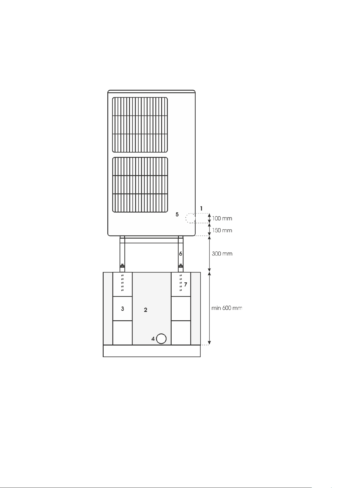
3.2 Preparation of space for the outdoor unit . . . . . . . . . . . . . . . . . . . . . . . . . . . . . . . . . . . . . . . 12
3.3 Fittingtheoutdoorunit ................................................. 15
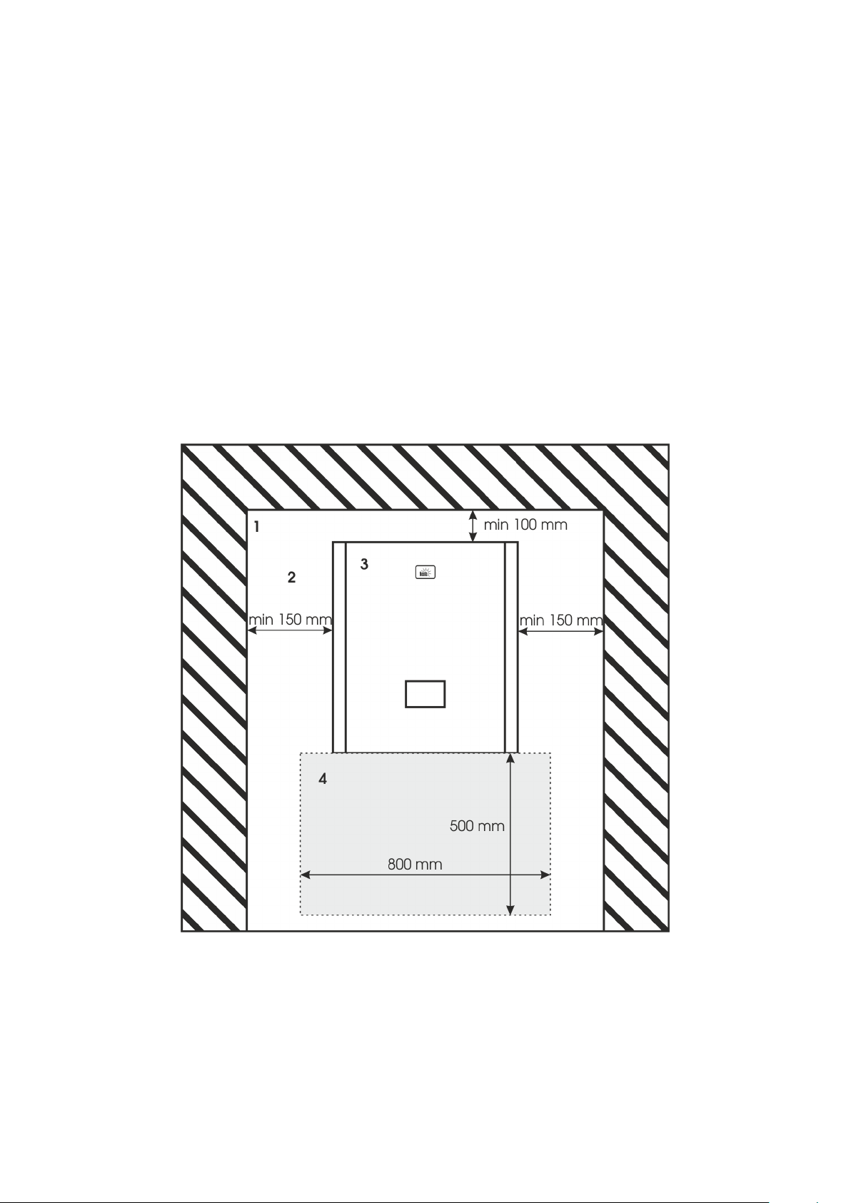
3.4 Preparation of space for the indoor unit . . . . . . . . . . . . . . . . . . . . . . . . . . . . . . . . . . . . . . . 15
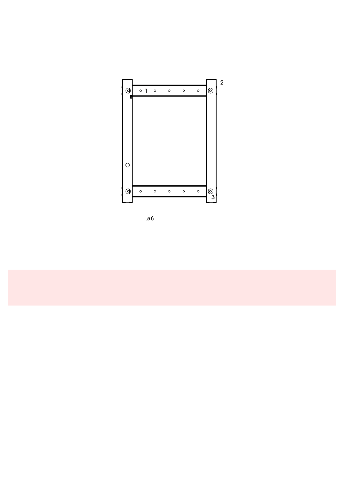
3.5 Indoorunitmounting .................................................. 16
3.6 Unitsconnection .................................................... 17
3.6.1 Refrigerantpiping ................................................ 17
3.6.2 Cableconnections ............................................... 21
3.6.3 Cableconnecting ................................................ 22
3.7 Connection of the heat pump to the heating system . . . . . . . . . . . . . . . . . . . . . . . . . . . . . . . . 24
3.7.1 Connectionmethodsfor:............................................ 29
3.8 Unauthorized connections to the heating system . . . . . . . . . . . . . . . . . . . . . . . . . . . . . . . . . . 30
4 Commissioning 31
4.1 Commissioning of the heating system . . . . . . . . . . . . . . . . . . . . . . . . . . . . . . . . . . . . . . . . 31
4.2 Activation ........................................................ 31
5 Shutdown 32
5.1 Short-termshutdown .................................................. 32
5.2 Long-termshutdown .................................................. 32
6 Faults and status messages 33
6.1 Errorcodestructure................................................... 33
6.2 Overview of faults and status messages . . . . . . . . . . . . . . . . . . . . . . . . . . . . . . . . . . . . . . . 33
6.3 Faultsandtroubleshooting............................................... 34
6.4 Statusmessages .................................................... 36
6.5 Protectivefunctions................................................... 37
6.6 Serviceorganization................................................... 40
7 Maintenance of the device and components 41
7.1 Maintenanceoftheoutdoorunit............................................ 41
7.2 Maintenanceoftheindoorunit............................................. 41
7.3 MaintenanceoftheDHWtank ............................................. 42
7.4 Maintenanceplan .................................................... 43
8 Design documentation 44
8.1 Connection of the heat pump to the heating system . . . . . . . . . . . . . . . . . . . . . . . . . . . . . . . . . 44
8.2 Hydrauliccircuit ..................................................... 47
8.3 Heating - range of working temperatures . . . . . . . . . . . . . . . . . . . . . . . . . . . . . . . . . . . . . . . 49
8.3.1 Floordryingprogram .............................................. 50
8.4 Cooling - range of working temperatures . . . . . . . . . . . . . . . . . . . . . . . . . . . . . . . . . . . . . . . 51
8.4.1 Dewpointtable ................................................. 51
8.5 Acousticparameters .................................................. 52
9 Technical data 53
9.1 Electrical wiring diagram of the indoor unit . . . . . . . . . . . . . . . . . . . . . . . . . . . . . . . . . . . . . . 53
2

9.2 Hydraulic wiring diagram of the indoor unit . . . . . . . . . . . . . . . . . . . . . . . . . . . . . . . . . . . . . . 54
9.3 StructuralBOM...................................................... 55
9.4 Dimensions........................................................ 56
9.5 Dimensionsofthewallbracket(pad) ......................................... 57
9.6 Removingthecover ................................................... 58
10 Manufacturer contact 59
10.1Documentsfordownload................................................ 59
10.2Onlinemanuals ..................................................... 59
3

1. Introduction
Installation manual extends User manual by more informations. This manual is designed primarily for construction com-
panies and heating engineers, which realise installation of outdoor and indoor unit of NeoRé heat pump and connect it to
the heating system.
Second part of this manual is designed for service organisations and engineers. In this part is an explanation of error
codes and instructions for device maintenance.
4

2. Safety instructions
2.1 Safety warning
URead the manual carefully before installing, putting into operation or maintaining the device. Adherence to the
described procedures for the installation and operation of the device is important for long-term and trouble-free
operation. Faults and defects caused by non-compliance with the safety instructions, installation procedures and
operating rules will not be taken into account, not even damage or destruction of other related equipment. The
device may only be installed by persons with appropriate qualifications in the field of heating, cooling and electrical
engineering.
In addition, observe all applicable safety regulations related to the actual installation and operation of the NeoRé
heat pump.
The device may only be operated by a person familiar with this manual and older than 15 years. Persons with limited
physical, sensory and mental capabilities or with lack of experience and/or knowledge may operate the device only
if they are supervised or trained in the safe use of the device by the person responsible for their safety and if they
understand the dangers involved. Children must not play with the device or clean or maintain it.
UThe R32 refrigerant is a class A2L flammable gas.
To install the indoor unit, observe the minimum floor area requirement. More in Installation
Manual, Table Minimum floor area when using A2L gas in Chapter Refrigerant piping.
UThe heat pump must be installed in a room without continuous open flame operation (e.g. running gas appliance)
and ignition sources (e.g. operating electric heater).
2.2 Safety precautions
UThe heat pump is an electric device working with a voltage of 400 V! The device may only be installed and serviced
by an authorized electrician. In case of fire, do not extinguish with water or foam. Use only a powder or snow
extinguisher!
In the event of a refrigerant leak, turn off all circuit breakers located on the indoor unit and contact the service
organization indicated on the plate on the indoor unit. The R32 refrigerant is slightly flammable, non-toxic. Under
no circumstances should you try to stop the refrigerant leak yourself. It reaches very low temperatures (up to
−50°C). In the event of a leak in the interior of a building, ventilate the room. In case of inhalation of refrigerant
vapours or fire fumes, take the affected person to a ventilated place and call for medical help: phone number 112.
In case of contact with liquid refrigerant, dry the area immediately and warm it, for example with a blanket. In case
of contact with eyes, rinse immediately with plenty of lukewarm water and call for medical help: phone number
112.
5

UIn case of fire, disconnect the device from the mains and extinguish with a snow or powder fire extinguisher.
In the event of a heating water leak, turn off all circuit breakers located on the indoor unit and contact your service
organization.
When handling the refrigerant piping (cleaning, maintenance), use personal protective equipment (gloves, goggles,
protective clothing, ...).
Do not put your hands or other objects in the fan area of the outdoor unit, there is a risk of serious injury!.
Do not expose yourself to the airflow from the outdoor unit for a long time. There is a risk of severe hypothermia!
U• Perform the installation only in accordance with the installation manual, which is available at
https://www.neota.cz/en/downloads/.
• Connect the outdoor and indoor unit (refrigerant, electric) only with the material specified in the installation
manual.
• Installation work on the refrigerant and electric circuit must be performed by an appropriately authorized
person.
• Do not use flexible inlets and piping to connect the units.
• Do not operate a device that is not completely installed.
• Do not use refrigerants whose quality and purity you are not sure about. Observe the safety precautions on
the refrigerant packaging.
• Do not add refrigerant to increase performance.
• Always use a vacuum pump before filling the refrigerant.
• Pay attention to work safety and personal protective equipment during installation.
• The device must be installed by a specialist company authorized by the manufacturer. Do not attempt to
install the device yourself. You can destroy the device or cause injury.
• Do not mix two types of refrigerant. Use only the refrigerant specified on the label.
2.3 Legal conditions
Legal conditions that must be observed when handling the device.
ČSN EN 378-4+A1:2020 Art. 6.5.x
All parts of refrigeration equipment, e.g. refrigerant, heat-transfer medium, filter, dehydrator, insulation material,
compressor and the whole refrigerant circuit system must be recovered, reused and/or properly disposed of in
connection with maintenance, repair and decommissioning. Maintenance and disposal must be performed by a
person professionally qualified for the disposal of refrigerants and oils.
ČSN EN 378-4+A1:2020 Art. 6.2.x
Used refrigerant that is not intended for reuse must be treated as waste for safe disposal. Prevent emissions to
the environment. Any handling of the refrigerant must be performed by a person professionally qualified for the
disposal of refrigerants and oils.
ČSN EN 378-4+A1:2020 Art. 6.2.x
Used oil recovered from refrigeration equipment that cannot be regenerated must be stored in a suitable separate
container and must be treated as waste for safe disposal. Oil must be drained by a qualified person.
ČSN EN 378-4+A1:2020 čl. 6.6
All activities related to recovery, reuse of refrigerant and refrigerant source must be recorded in the refrigeration
equipment’s operating log (see En 378-4 Art. 4.2). If required, it must be provided by the refrigerant supplier or
service company.
6

2.4 Storage and transport conditions
Indoor unit NeoRé IU16-20
Environment dust-free, non-aggressive
Temperature range -10 to 45°C
Relative humidity max 70%
Outdoor unit OU GMx or OU GPx
Environment dust-free, non-aggressive
Temperature range -10 to 45°C
Relative humidity max 90%
The outdoor unit must be stored and transported in a vertical position in the original packaging and properly se-
cured. If necessary, protect fragile parts, especially the evaporator, from damage. Overturning or leaking refrigerant
may lead to injury.
During transport, all components of the device must be secured with straps or other technical means to prevent over-
turning and injury.
UIf damage or refrigerant leakage occur during transport, do not attempt to stop the leak improperly. Evaporation of
the refrigerant significantly cools the affected areas and may cause injury in contact with the skin.
7

2.5 Table of technical parameters
Figure 2.1: Table of technical parameters
8

3. Installation manual
UThe heat pump may only be installed in accordance with the safety instructions, see chapter 2 Safety instructions
(p. 5).
3.1 Working conditions
The heat pump can be used as a heat source for
• heating
• water heating
• cooling
UFreezing of the coolant exchanger - The basic protection against freezing of the coolant/water exchanger is to
ensure minimum flow through the exchanger, see project documentation. Such accident of the coolant exchanger
can only occur during defrosting the evaporator, or cooling. It is necessary to ensure that no control element is
inserted in the heating circuit, that could close or significantly reduce the heating water circulation. When starting
the heat pump for the first time and after a shutdown, ensure that the water in the heating circuit has at least 20°
C.
UAccording to ČSN 33 2000-3, the heat pump must not be located and installed in an environment with a risk of
explosion of flammable gases.
3.1.1 Working environment
environment according to ČSN 33 2000-3 for an outdoor unit AA2; AA3; AA4; AA5; AB7; AD3
environment according to ČSN 33 2000-3 for an indoor unit AA5; AB5
9

Technical parameters of el. connections
nominal voltage 3x400/230V; +/-10%; 50Hz
maximum power according to table of technical parameters
grid type TN-CS according to ČSN EN 33 2000-3
ingress protection I according to ČSN EN 60335-1
outdoor unit ingress protection IPX4
indoor unit ingress protection IP40/20 (with / without cover)
Table 3.1: Technical parameters of el. connections
3.1.2 Cooling circuit
refrigerant R32, CH2F2, GWP 675, refill by type (table of technical parameters on p. 8)
maximum overpressure 4.2 MPa
The working range of output water temperature can be found in the figure 8.3 on page 49.
3.1.3 Technical parameters of heating / cooling water
Before the installation we recommend to make water analysis. Each material reacts when come to touch with water. Type
of reaction depends on substances containde in water. Water with higher content of salt, calcium and magnesium sedimenst
in form of limescale after warming up to 60°C. It is an irreversible procedure which causes significant deterionation of whole
device and significant decrease of efficiency.
Generally recommended operating water parameters:
• pH 6,5-8,5
• conductivity under 350 µs/cm
• hardness 2-6°dH
• bacteria NE
• mechanical impurities NO
3.1.4 Technical parameters of water
Inlet water quality for stainless steel tank must not exceed following parameters:
• Calcium (Ca) + Magnesium (Mg) = 1,25 mmol/l
• Ferrum (Fe) = 0,2 mg/l
• Mangan (Mn) = 0,05 mg/l
• Chloride (Cl) = 0,03 mg/l
• Chlorides = 100 mg/l
• Water hadrness less than or equal to 7°dH
10

UIf the inside of water tank will be damaged in cause of exceeding the parameters of water, there is no claiming
warranty from the manufacturer.
If the water does not meet parameters, it is needed to connect a mechanical filter to cold water inlet and install convient
water threatment.
More in chapter 7.3 Hot water tank maintenance (p. 42)
Overpressure and temperature
highest overpressure 2,5 bar
highest working overpressure 0,8 bar
highest working temperature 60°C
Table 3.2: Overpressure and temperature
The minimum heating water flow rate for each power type is shown in the figure 8.2 on page 48.
11

3.2 Preparation of space for the outdoor unit
UWhen choosing an area for the outdoor unit, it is necessary to consider current legislation and choose the location
so that the day-time or night-time noise limits on the site boundaries are not exceeded. Ambient materials (wall,
bushes, solid area, green area, etc.) significantly affect propagation of noise. Therefore, it is advisable to draw up
a noise study prior to physical location of the outdoor unit.
When choosing an area for the outdoor unit, it is necessary to keep the minimum distances from the surrounding objects
for the sake of air flow through the device. Failure to observe these distances may have a major impact on the correct
functioning and performance of the device.
It is also necessary to secure the unit against tipping and ensure condensate drainage from the unit so that no ice freezes
are formed under it in the winter months. The condensate drainage method depends mainly on the climatic conditions in
which the unit is installed. Heating cable under unit is recomended in cold climate, to melt an ice and help the water soak
up. The space around the unit must be maintained clear of snow and other things.
Minimum spacing distances
Figure 3.1: Drawing of foundation for the outdoor unit - floor plan
1 - wall; 2 - passage through the wall into the interior; 3 - drainage pit;
4 - concrete masonry; 5 - drainage hose
12

Dimensions dependent by outdoor unit type
Outdoor unit dimension A
NeoRé 5, 8, 11, 14 TGx, NeoRé 16 TGx HP 600 mm
NeoRé 8, 11, 14 TGx HP 620 mm
Table 3.3: Console pitch depending on outdoor unit type (x = TX or MINI)
Images 3.1 and 3.2 (p. 14) show the way space can be prepared for installation of the outdoor unit. The image 3.1 indi-
cates minimum distances from the walls. This is the worst acceptable scenario that still enables proper functioning of the
device. There must be no fixed obstacle in front of the unit, at least one meter away. Always ask supplier for the correct
install method for your system.
The dimensions of the drainage pit are, again, marked with regard to good functionality and convenient implementation.
Inside the drainage pit, there are masonry blocks filled with concrete. During casting, it is advisable to insert threaded rods
that will anchor the console under the outdoor unit, into the concrete pillars. Another option is to anchor the threaded rods
with chemical mortar.
At the bottom of the drainage pit, especially if the soil is clayey and impermeable, it is recommended to insert a drainage
hose, which must be at least 800 mm outside the drainage pit, covered in geotextile and stored in pebbles. Likewise, the
entire area of the drainage pit will be filled with pebbles to ensure proper water drainage and allow it to soak into the subsoil.
To fit the outdoor unit, use a console to ensure that the unit is higher than the surrounding terrain. This results in a lower
rate of clogging of the exchanger with surrounding dirt from the ground and, above all, the passage of air through the snow
in winter is not limited. Before fitting the outdoor unit, the console must be mounted.
The passage through the wall needs to be higher than the outlets from the outdoor unit, so that during rain, water will run
off the object.
13

Figure 3.2: Outline drawing for the outdoor unit - front view
1 - passage through the wall into the interior; 2 - drainage pit;
3 - concrete masonry; 4 - drainage hose; 5 - outdoor unit;
6 - console with anti-corrosive finish 7 - bracket for console mounting
14

3.3 Fitting the outdoor unit
Before fitting the outdoor unit, it is necessary to check whether the console, on which the unit is to be mounted, is well
anchored. Under no circumstances should the outdoor unit be fitted unless the console is securely anchored.
The outdoor unit must be fitted with a minimum of two workers. Once seated on the console, one of the workers holds
the unit in a stable position while the other one secures the unit with screws at the bottom. The entire concrete foundation
assembly, including the console and the outdoor unit, is shown in the picture 3.2 (p. 14).
The unit must be attached to the bottom console with M6x70 mm screws and these must be tightened properly.
3.4 Preparation of space for the indoor unit
The indoor unit is designed for wall mounting. Upon installation, you need to keep the minimum wall and ceiling distances
that are shown in the picture 3.1 p. 12. There is an allocated space under the unit itself that should be kept free for the
connection of the heating circuit, refrigerant piping and cable connections.
It is also necessary to take into account the weight of the device and choose the appropriate wall and anchoring tech-
nology with respect to it.
Figure 3.3: Indoor unit placement
1 - walls and ceiling; 2 - interior space; 3 - indoor unit;
4 - space for cable and pipe connections
15

3.5 Indoor unit mounting
After selecting the appropriate space to place the indoor unit, first step is to fix a mount pad on the wall. There are holes
in the pad that anchor it to the wall by fixing with screws. Recommended screws are min. 5x70.
When anchoring, keep in mind that the mounting pad will have to bear the weight of the entire indoor unit. Therefore, it
is necessary to use an anchoring system with sufficient load-bearing capacity and suitable for material of the relevant wall.
Figure 3.4: Mounting pad of the indoor unit for wall mounting
1 - hole for wall anchoring
✤
6 mm; 2 - fixtures for hanging the indoor unit;
3 - hole for fixing the indoor unit to the mounting pad with a M4x15 mm screw;
The mounting pad is shown in the picture 3.4 (p. 16) After fixing the mounting pad, it is possible to hang the indoor unit.
Due to the size and weight of the unit, at least two workers are required to hang it on the pad. The indoor unit hangs on hooks
that are located directly in the back of the unit. After hanging the unit, it is necessary to secure the it against unwanted falling
with two screws at marked places at the bottom.
UHandling, hanging and mounting the indoor unit requires at least two workers and the use of personal protective
equipment.
16

3.6 Units connection
Several connections must be made between the indoor and the outdoor units without which the heat pump as a whole
will not be able to operate.
It is necessary to prepare the piping for the refrigerant circuit where the heating medium is transferred. Then it is neces-
sary to prepare the power supply cable for the indoor unit, the power supply cable for the outdoor unit, the indoor / outdoor
communication cable, the outdoor temperature sensor cable and optionally the indoor temperature sensor. The location
of the temperature sensors must be consulted with a specialist as their improper location can have a major impact on the
quality of the heat pump operation.
Figure 3.5: Interconnection of indoor and outdoor units
1 - outdoor unit; 2 - indoor unit; 3 - refrigerant piping;
4 - power supply cable for the outdoor unit; 5 - communication cable; 6 - power supply cable 5x4 mm2
3.6.1 Refrigerant piping
UIt is very important to prevent any dirt and moisture from getting into the pipes of the refrigerant piping. Dirt or
moisture could cause damage or even complete destruction of the entire device.
It is also advisable that the pipeline outside the building is as short as possible and well insulated to minimize the
losses. If the pipeline is buried underground, moisture insulation, in addition to thermal insulation, is required.
The indoor and outdoor units must be interconnected by a pair of pipes, one of which serves for leading liquid refrigerant
and the other for refrigerant in gaseous state. It is necessary to use a thick-wall copper tubes for refrigeration with a polished
inner wall. For gaseous refrigerant, a 5/8 inch diameter and 1mm wall thickness is intended. A 3/8 inch diameter and 1
mm wall thickness tube is intended for liquid refrigerant. Greater wall thickness is used for increased durability and longer
service life. Nevertheless, care must be taken when handling and shaping the pipes to avoid sharp bends and breaks. Use a
cutting wheel to divide the pipes.
Type Liquid refrigerant Refrigerant gas
NeoRé 5TG 1/4" (6,4 mm) 1/2" (12,7 mm)
NeoRé 8,11,14,16TG (HP) 3/8" (9,52 mm) 5/8" (15,88 mm)
Table 3.4: Refrigerant pipe diameter, wall thickness 1 mm
17

UR32 refrigerant is an A2L class flammable gas.
R32 refrigerant is very low flammable and difficult to ignite. The burning rate is 6.32 cm/s.
A spark generated by the electrical switching elements or the lighting switch, for example,
do not have sufficient energy to ignite the R32-air mixture.
The minimum floor area condition must be met to install the indoor unit.
According to EN 378, the minimum floor area for residential installations is determined while using A2L gas, see table. If
the minimum floor area condition is not met, it is necessary to ventilate the room.
UIn the case of room ventilation, the ventilation openings must be unobstructed
Type Minimum floor area
NeoRé 5 TG 1,72 m2
NeoRé 8,11,14 TG 4,17 m2
NeoRé 8 TG HP 3,41 m2
NeoRé 11,14,16 TG HP 9,1 m2
Table 3.5: Minimum floor area when using A2L gas
UTo work with R32 refrigerant, the installer must have a valid Ministry of Environment certificate according to EU
regulation 2015/2067. It is also necessary to use special tools (vacuum pump, aspirator) approved for use with
R32. Avoid mixing oxygen with R32. Always use nitrogen to test for leaks of pipeline.
UThe refrigerant should be handled with care, and protective equipment to protect skin, face and eyes from possible
frost damage should be worn.
UIn case of capping, do not use any mineral oils. Mineral oils can reduce the service life of the equipment.
If the pipes are connected by soldering, a hard solder must be used (min. 30% Ag) and the piping must be filled
with nitrogen to prevent scale formation. The gas must not be pressurized.
Use insulation suitable for refrigerant circuits. Pipe surface temperature can reach up to 120°C! For outdoor use, use
insulation at least 20 mm thick. For interior spaces, 10-15 mm is sufficient. These parameters apply to insulation
that meets a thermal resistance of 0.045W / (mK) or better (at 20°C)
The refrigerant piping that is laid in a convenient manner should be connected to the indoor and outdoor units. It is
important to check the pipe ends for cleanliness before starting the connection. If the ends of the refrigerant piping are
not clean or there is even a suspicion there might be dirt inside the pipeline, the pipeline must be replaced with a new one.
Otherwise, the entire device may be damaged or destroyed.
Use only quality refrigeration tools. Cutting of the pipes by a cutting wheel prevents sawdust formation. First, it is nec-
essary to get rid of the inside edges of the pipe left by the cutting wheel. Subsequently, the UNF-SAE nut is attached to the
pipeline and a capping cup is formed at the end of the piping with size fitting the nut. Its parameters are listed in the table3.8.
Now, connect the pipes to the coolant outlets of the indoor and outdoor units with nuts.
18

After connection, the piping must be vacuumed. Do this in several steps:
1. First unscrew the plug from the three-way service valve (gas). Connect a pressure gauge suitable for vacuum and
vacuum pumps.
2. Start the vacuum pump and vacuum for about 15 - 20 minutes. Do not open the three-way valves.
3. Perform a leak test by shutting off the pump and checking the manometer after 60 minutes.
4. If the refrigerant has been refilled, disconnect the service hose (mind refrigerant leakage - use protective equipment). In
case there was no refrigerant filling, slowly open the three-way valve (liquid) and fill the pipeline up to the atmospheric
pressure (check the pressure gauge). You can then disconnect the service hose and screw in the service access plug.
5. Open both three-way valves (liquid first). Put the plugs back and tighten them.
6. Check the refrigerant circuit for leakage through the refrigerant leak detector.
After completing this process, the connection of the refrigerant circuit is complete.
UDo not exceed the maximum pipe length. If the maximum pipe length is exceeded, the parameters of the equipment
may deteriorate and the compressor may be destroyed.
UIf pipes are laid in the ground, they must be sufficiently insulated and protected from contact with water. The
manufacturer recommends using Flexalen Protect Tube 150 with end cuffs.
Unit type Pipe dimension Length Height difference
NeoRé 5 TG 1/4", 1/2" 5 - 25 m max. 10 m
NeoRé 8,11,14 TG 3/8", 5/8" 5 - 25 m max. 10 m
NeoRé 8 TG HP 3/8", 5/8" 3 - 30 m max. 10 m
NeoRé 11,14,16 TG HP 3/8", 5/8" 3 - 40 m max. 10 m
Table 3.6: Pipe capping 1
Distance in meters Coefficient
5-10 m k=1
10-15 m k=0,98
15-17 m k=0,95
17-25 m k=0,92
25-30 m k=0,89
Table 3.7: Nominal power loss coefficient depending on the length of the refrigerant piping
Example: The NeoRé 11 TG with a coolant pipe distance of 25 m with and basic output of 10 kW. The result nominal
output will be 9.2 kW according to a coefficient of 0.92.
19

Pipe diameter Diameter of hem A Overlap B
6,4 mm (1/4") 9,1 mm 0 - 0,5 mm
12,7 mm (1/2") 16,6 mm 0 - 0,5 mm
9,5 mm (3/8") 13,2 mm 0 - 0,5 mm
15,9 mm (5/8") 19,7 mm 0 - 0,5 mm
Table 3.8: Pipe capping 2 - sizes
Figure 3.6: Pipe capping
When tightening, hold the torque wrench at right angle to the pipe.
Figure 3.7: Tightening plated connections
Pipe diameter Tightening torque
1/4" 14 - 18 N*m
1/2" 49 - 61 N*m
3/8" 33 - 42 N*m
5/8" 68 - 82 N*m
Table 3.9: Tightening torque
20
This manual suits for next models
8
Table of contents
Popular Heat Pump manuals by other brands

Danfoss
Danfoss DHP-H user manual

Samsung
Samsung VRF DVM S2 Technical data book

Carrier
Carrier Weathermaster III 38HQ Installation, Start-Up and Service Instructions

McQuay
McQuay Enfinity series Installation & maintenance data

Nibe
Nibe F1155 Series Installer manual

Daikin
Daikin ROTEX RHYHBH05AA installation manual