Operating Manual
Breite: 170
Höhe:8,15
Oben Links
278,5 20
RIFOX - Hans Richter GmbH Spezialarmaturen Fon: +49 (0) 421 499 75 - 0 Internet: www.rifox.de
Bertha-von-Suttner
-Str
.
9
D-28207
Bremen
Fax:
+49
(0)
421
499
75
-
40
Email:
[email protected]Page 3 of 5
08/2020 -Di. Subject to modifications
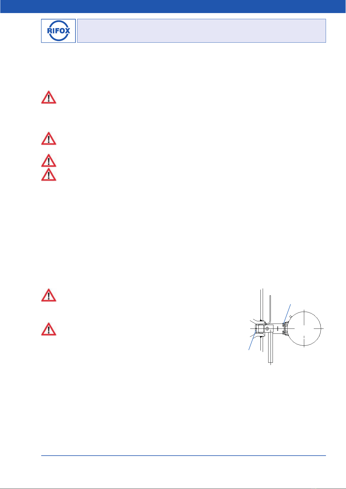
3 Assembly
■The condensate trap has to be screwed into a pipeline between flanges.
■Remove transport caps from inlet and outlet.
■Fitting direction: according to Picture 1 and Picture 2.
■Supporting brackets: The weight of the condensate trap must be taken up by the supporting brackets, which are welded
onto the housing.
■To avoid downtimes, it is recommended to install stop valves with bypass to pipeline, both in front of and behind the con-
densate trap.
4 Start-Up
Shut off the housing on both sides during strength tests with PT pressure.
The float-controlled unit is only suitable up to PS pressure value or alternative PT value shown in brackets according name
plate.
The lower value is max. allowable pressure. A pressure test with design pressure (PT) will destroy the float.
The pressure build-up and heating-up of the housing should not take place abruptly. If leakage is detected after the first
inspection, the screws (4 / 6 / 10 / 11) can be fixed under consideration of the given torque moments, as given in Section
6.5. The screws can only be tightened on when the housing is unpressurized and at room temperature.
5 Observation and control
The function’s failure can be observed either as condensate blockage or as gas/ steam leakage.
■Condensate blockage can be determined by a): loosen the control screw (4) for a quarter rotation, while no condensate
leakage should occur; and by b): a surface thermometer on the housing for steam applications (if necessary, please consult
with Rifox).
■Gas / steam leakage: can be determined by an ultrasonic measuring device, and for steam applications by a surface
thermometer. In case of steam leakage, open the condensate trap according to Section 6.1. Make sure that float (8) can be
easily moved. If necessary, disassemble and clean the float control assembly (8). If damages/ wears are detected on parts or
on the sealing surface, the complete float control assembly (8) should be replaced.
6 Maintenance / Inspection
6.1 Opening the steam trap and dismantling the float control
■The steam trap must be depressurized. Shut off the system securely in
front of and behind the steam trap.
■Release any remaining pressure in the housing by loosening the control
screw (4) by only a quarter turn.
■Dismantle the steam trap from the pipeline system. Loosen the flange
connections and lift out of the pipeline carefully and place on the floor. At-
tention: The condensate trap weights from 46 kg up to 48 kg depending on
the connection sizes. Lifting device is required.
■Loosen the housing screws (12) evenly crosswise. Put down the housing
cover (1). Attention: the housing cover weights about 8kg.
■The float control is dismantled with a centering aid that is inserted in
the bushing that is provided with 2 slots. By turning counterclockwise (3-4
turns), the Holding screw (10) is screwed out of the control support body (9). The control is detached from the seat cone by
means of gentle blows with a hammer on the front end of centering aid.
■Screw out the Holding screw (10) completely.
■Remove float control assembly (8) through the cover opening.
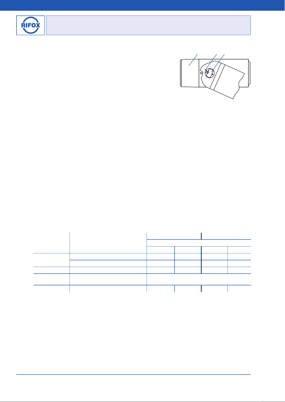
■For removal of special float: Loosen, unscrew and remove the screws. See Picture 5.
Picture 5
Special
Float
Screws
Holding screw