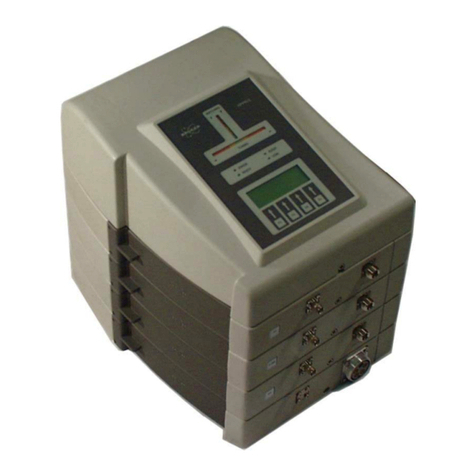
Nepagene ELEPO21 User manual


Important Information
i
Important Information
This product is authorized for laboratory research use only, not medical
product. The product has not been qualified or found safe and effective for
any human or animal diagnostic or therapeutic application. Uses for other
than the intended use may be a violation of applicable law.
The In Vitro High Voltage Electroporator ELEPO21 is an electroporation device designed to provide a
convenient way to introduce materials such as foreign DNA into sample’s cells, bacteria, fungi and
yeasts. This manual provides instructions for proper setup and operation of the ELEPO21 and its
components.

Safety Precautions
ii
Safety Precautions
Safety Terms and Symbols
Danger
Disregarding instructions marked with this symbol may lead to serious injury
or death.
Warning
Disregarding instructions marked with this symbol may lead to serious injury
or property damage.
Caution
Disregarding instructions marked with this symbol may lead to injury or
property damage.
General cautions
Danger
1) Do not use outside the range of product specification. Comply with the
contents described in this instruction manual when using the product.
2) Do not modify or perform unnecessary disassembly. It may cause
electrocution to the user and malfunction or damage to the device.
Handling precautions
Danger
Do not touch the voltage output sockets on the device during the delivery of
the electric current, i.e., after pressing the start button or the foot switch.
To touch these parts during the delivery of an electric current is extremely
dangerous and will cause an electric shock.

Safety Precautions
iii
Warning
1) Do not open the cover of the product when the power is ON.
2) Do not touch the un-insulated parts of cables and electrodes when power
is on.
3) Do not operate this product in any of the following scenarios:
There is physical damage to the product.
Smoke, strange noise or fumes come from the product.
Contact your supplier immediately.
Location of warning labels
Caution
The warning labels must always be legible. Ensure that the warning labels
are properly placed and legible. If a warning label is illegible or is peeling off,
contact us to replace it.
Power source, grounding and wiring cautions
Warning
1) To avoid the risk of fire, or electrical shock, observe all ratings and
markings on the product. Consult this manual for further ratings
information before making connections to the product.
2) This product is grounded through the grounding conductor of the power
cord. To avoid electric shock, the grounding conductor must be connected
to an earth grounding.
3) Use only the following power supply cord. Using the wrong power cord
could result in danger or fire.
・For AC100-120V area
UL Listed, detachable power cord set, 3 conductor grounding Type
SVT, No. 18 AWG, 3 m long maximum, rated at AC125V minimum.
・For AC220-240V area
Approved according to EU/EN standards, 3 conductor grounding
Type H05VV-F, 3 m long maximum, rated at AC250V minimum.
4) Do not bend the power cord forcibly or place heavy object on the cord
because it might damage the cord and cause fire or electric shock.

Safety Precautions
iv
Caution
1) Be sure to hold the connector part of the power cable when disconnecting
the cable. Pulling on the cord section may cause it to fray and break.
2) Disconnect power cable from the product if the product is not in use.
Usage environment precautions
Caution
1) Do not install or store the product in locations such as those listed below:
Locations subject to direct sunlight
Locations subject to strong impact or vibration
Location subject to high temperatures or high humidity
Locations that are submerged in water
2) Do not use this product with corrosive fluids. Avoid operation in humid or
corrosive environments.
3) Do not bring a strong magnet or magnetic field close to the main body of
the product.
4) Refer to installation instructions for details on installing the product to
ensure proper ventilation.

Table of Contents
v
Table of Contents
Important Information ............................................................................................. i
Safety Precautions................................................................................................. ii
Table of Contents ................................................................................................... v
1Checking the Package.................................................................................1-1
2Related Products ......................................................................................... 2-1
3Part Names...................................................................................................3-1
4Installation and Connecting ........................................................................4-1
4.1 Installation........................................................................................................... 4-1
4.2 Connecting ......................................................................................................... 4-2
5Operating Instructions.................................................................................5-1
5.1 Overview............................................................................................................. 5-1
5.2 Setting Electric Pulse Parameters...................................................................... 5-1
5.2.1 Display in Selection window............................................................ 5-1
5.2.2 Parameters of Poring Pulse mode.................................................. 5-2
5.2.3 Setting parameters of Poring Pulse mode ...................................... 5-2
5.2.4 Parameters of Transfer Pulse mode ............................................... 5-4
5.2.5 Setting parameters of Transfer Pulse mode ................................... 5-4
5.2.6 Setting current limit.......................................................................... 5-5
5.3 Saving, Copying and Recalling the Program...................................................... 5-6
5.4 Measuring Electrical Impedance ........................................................................ 5-8
5.5 Executing Program (Delivering Electric Pulses)................................................. 5-8
5.6 Displaying Output Electric Pulse Parameters..................................................... 5-9
6Additional Information.................................................................................6-1
6.1 Specifications...................................................................................................... 6-1
6.2 Proper Selection of The Power Supply Cord...................................................... 6-3
6.3 ELEPO21 Novel 2-Step Multiple Pulses Regime ............................................... 6-4
6.3.1 About pulse waveform .................................................................... 6-4
6.3.2 Poring Pulse and Transfer Pulse .................................................... 6-5
6.4 Warranty ............................................................................................................. 6-6

Table of Contents
vi

1Checking the Package
1-1
1 Checking the Package
ELEPO21 Electroporator x 1
Accessories
Power cord x 1
Instruction Manual (this manual) x 1


2Related Products
2-1
2 Related Products
CU500 Cuvette Chamber
The CU500 Cuvette Chamber can be connected to the ELEPO21 electroporator and is used for cell
transfection with NEPA electroporation cuvettes. Electric pulses from the ELEPO21 are delivered
through this product.
NEPA Electroporation Cuvettes
EC-001S, EC-002S, EC-004S, EC-001, EC-002 and EC-004
.
NEPA Electroporation Cuvettes are available in three gap widths: 0.4, 0.2, and 0.1 cm, to facilitate
delivery of the proper field strength to a variety of cell types.
Simply fill the cuvette with the sample using the transfer pipette and place the cuvette in the CU500
Cuvette Chamber.
Cat #
Description
Unit
EC-001S
NEPA Electroporation Cuvettes with a pipette
1mm gap, 20~70µl (Brown color cap)
50/pkg
EC-002S
NEPA Electroporation Cuvettes with a pipette
2mm gap, 40~4000µl (Green color cap)
50/pkg
EC-004S
NEPA Electroporation Cuvettes with a pipette
4mm gap, 80~800µl (Blue color cap)
50/pkg
EC-001
NEPA Electroporation Cuvettes
1mm gap, 20~70µl (Brown color cap)
50/pkg
EC-002
NEPA Electroporation Cuvettes
2mm gap, 40~4000µl (Green color cap)
50/pkg
EC-004
NEPA Electroporation Cuvettes
4mm gap, 80~800µl (Blue color cap)
50/pkg

2Related Products
2-2

3Part Names
3-1
3 Part Names
Front
Rear
Power Inlet
RS232C port
Cooling fan
Power Switch
Voltage Output
Control Panel

3Part Names
3-2
Control Panel
1. Poring Pulse window
Set Parameters frame
A. Voltage [V]
Display the set pulse voltage value.
B. Pulse Length [msec]
Display the set pulse length in milliseconds.
C. Pulse Interval [msec]
Display the pulse interval (duration between pulses) in milliseconds.
D. Number of Pulses
Display the number of set pulses.
E. Polarity [+ / +/-]
Display the set decay rate of pulses.
Measurements frame
F. Voltage [V]
Display the measured output voltage value.
G. Current [A]
Display the measured output current value.
H. Energy [J]
Display the calculated output pulse energy in joules.
4
1.
2.
3
5.
A
B
C
D
E
F
G
H

3Part Names
3-3
2. Transfer Pulse window
Set Parameters frame
A. Voltage [V]
Display the set pulse voltage value.
B. Pulse Length [msec]
Display the set pulse length in milliseconds.
C. Pulse Interval [msec]
Display the pulse interval (duration between pulses) in milliseconds.
D. Number of Pulses
Display the number of set pulses.
E. Polarity [+ / +/-]
Display the set electrical polarity (+ only or +, followed by -).
Measurements window
F. Voltage [V]
Display the measured output voltage value.
G. Current [A]
Display the measured output current value.
H. Energy [J]
Display the calculated output pulse energy in joules.
3. Selection window
A. Poring Pulse frame
Illuminate the editable parameter.
B. Transfer Pulse frame
Illuminate the editable parameter.
C. Others frame
Illuminate the editable item.
4. Impedance window
A. Impedance [kΩ]
- Display the electrical impedance value between the electrodes by
pressing Ωbutton.
- Display the program number as “Ch.XX”when Memory in Others frame
in Selection window is selected and lighting up.
A
B
C
D
E
G
H
A
B
C
F
A

3Part Names
3-4
5. Button Keys
A. Ω
Execute the impedance measurement function between the electrodes
B. Data
Send the data of the set and measured parameters.
C. Meas.
Display the measured parameters.
D. Copy
Copy the set parameters to another program number.
E. ◄▴▾▸
Select the parameter/item to be edited.
Change the displaying of Measurements.
F. Set
Enable the edit of the parameter to be modified.
G. Start
Execute the program (pulsing).
H. Stop/Clear
Cancel the program or the parameter editing.
Delete the entered value.
I. Numerical keys
Enter the numerical value.
J. Enter
Save the entered value.
Execute the recall of the program.
A
B
C
D
E
F
G
H
I
J

4Installation and Connecting
4-1
4 Installation and Connecting
4.1 Installation
Precautions for installation
Installation site
The ELEPO21 must be installed on a flat-level area.
Spacing for the cooling fan
Caution
Be sure to leave a clearing of at least 20 cm behind the instrument for proper
ventilation.
4.2 Connecting
Precautions for wiring a power supply and grounding
Warning
1) Observe all ratings and markings on the product and confirm that they
correspond to the electrical conditions in the laboratory.
2) Use only the power cord specified for this product and certified for the
country of use. If no power cord is provided, please select the power cord
by referring to the section 6.2 Proper Selection of The Power Supply
Cord.
3) Connect the cable after confirming that the power switch is set to OFF.
4) Be sure to ensure that there is a protective earth before using the
instrument. Otherwise, there is a danger of electric shock. For safety
reasons and to minimize or remove unnecessary noise, be sure to ground
the instrument.
Grounding with the 3-pin plug
Insert the 3-core plug into a three-core outlet according to the following
figure
20cm

4Installation and Connecting
4-2
Precautions for wiring of electrodes
Warning
Connect the caballing after confirming that the power switch is set at OFF.
Connecting Cuvette Chamber
1 ) Insert the male banana plugs of the CU500 Cuvette Chamber (optional) into the voltage output
slot located on the front panel of the ELEPO21.
2 ) Open the lid of the CU500 and then insert an electroporation cuvette (optional) into the insertion
slot of CU500.

5Operating Instructions
5-1
5 Operating Instructions
5.1 Overview
The basic steps required to perform electroporation experiments using the ELEPO21 Electroporation
System are as follows:
5.2 Setting Electric Pulse Parameters
5.2.1 Display in Selection window
An indicator light corresponding to the selected parameter/item lights up. Select the parameter/item by
pressing ◄▴▾▸buttons. The light corresponding to the selected parameter/item will change
accordingly.

5Operating Instructions
5-2
5.2.2 Parameters of Poring Pulse mode
Voltage
The voltage of the first Poring Pulse (increments: 1V)
Pulse Length
The time duration of one Poring Pulse in milliseconds (increments: 0.1ms)
Pulse Interval
The time interval between Poring Pulses or the last Poring Pulse and the first Transfer Pulse in
milliseconds (increments: 0.1ms)
Number of Pulses
The number of Poring Pulses
Polarity Switching
This function reverses the polarity of Transfer Pulses. When the “+” indicator of the Polarity selection
option in the Set Parameters frame is illuminated, it means that the polarity switching function is OFF.
When the “+/-“indicator of the Polarity selection option is illuminated, it means that the polarity switching
function is ON. If the voltage, number of pulses are programmed, the out put pulses will be as follows;
5.2.3 Setting parameters of Poring Pulse mode
1 Use the ◄▴▾▸buttons to select the desired parameter from within the Poring Pulse mode Selection
window.
2 When your choice is made: Press the Set button.
Time
Voltage

5Operating Instructions
5-3
3 Enter the desired value by pressing the numerical keys.
4 If you would like to cancel an entered value, press the Stop/Clear button.
5 Press the Enter button to save the desired value. When the value is saved, a short beep will sound
twice.
*If a value out-side of the specification range is selected and the Enter button is pressed to confirm the
selection, a long beep will sound three times and the previously selected value will be automatically
cancelled. Please re-enter a correct value within the specification range.
6 The entered values are displayed in the Set Parameters frame in the Poring Pulse window. When a
displayed value is blinking, it means that the value has not been saved yet.
Table of contents
Popular Laboratory Equipment manuals by other brands
Thermo Scientific
Thermo Scientific TSQ Endura Hardware manual

Vernier
Vernier Red Tide USB650 manual

VERDER
VERDER Carbolite Gero HT 4/350 Installation, operation and maintenance instructions
Magellan
Magellan LeadCare II Quick reference guide
Shimadzu
Shimadzu LC-40D X3 CL instruction manual
Helmer Scientific
Helmer Scientific QuickThaw DH2 Operation manual
