dentronix DDS 7000 User manual
DDS 7000
Dry Heat Sterilization System (115V/230V)
Operating Instructions

2

3
TABLE OF CONTENTS
INTRODUCTION 4
GENERAL AND TECHNICAL SPECIFICATIONS 5
DDS 7000 UNIT OVERVIEW 6
UNPACKING YOUR DDS 7000 7
SERIAL NUMBER LABELS 7
SELECTING YOUR STERILIZATION AREA 8
VENTING 9
CONNECTING TO A POWER SOURCE 10
STERILIZER CONTROLS 10
INDICATOR LED LIGHTS 11
DIGITAL TEMPERATURE DISPLAY 11
DOOR LATCH 11
SAFETY DOOR INTERLOCK 12
FIRST TIME USE CYCLE TEST 12
STERILIZING YOUR INSTRUMENTS 12
INSTRUMENT HANDLING 13
PLIER RACKS 14
LOADING YOUR DDS 7000 PLIER RACKS 14
LOADING THE STERILIZATION CHAMBER 16
OPERATION 17
SPECIAL NOTE ON MOUTH MIRRORS 19
ABORTING A CYCLE 20
RESETTING THE TEMPERATURE OVERLOAD SENSOR 20
BIOLOGICAL TESTING IN YOUR STERILIZER 21
MAINTENANCE AND CLEANING 22
SELECTING USER OPTIONS 24
USING THE COM PORT 26
WARRANTY / RETURN POLICY 28
STERILIZER RETURN PROCEDURE 28
APPENDIX I (SYMBOL EXPLANATION). 29
APPENDIX II (ERROR CODES) 30

4
INTRODUCTION
Thank you for your purchase of the DDS 7000 Dry Heat Sterilization System. We appreciate your
commitment to safe sterilization and eective patient care. The DDS 7000 Dry Heat Sterilizer is a
convection type unit, designed for the sterilization of un-bagged orthodontic instruments that can
withstand temperatures of up to 420ºF(215ºC). The DDS 7000 System is programmed to rap-
idly increase load temperature to 374ºF (190ºC), maintain this temperature for an eective and
complete kill in three (3) minutes and then quickly cool the load for immediate handling. Optimum
results are achieved with the Dry Heat method by uniform load distribution. Your DDS 7000 is
equipped with a unique rack system for sterilizing hinged instruments. This design guarantees equal
spacing of instruments and racks in the sterilization chamber and greatly simplies loading, han-
dling, and dispensing of all instrumentation. Since no moisture, pressure, or chemicals are used in the
DDS 7000 sterilization cycle, your valuable instruments are protected from rust, corrosion, and dulling
of cutting edges. The design includes a safety interlock switch on the door to prevent access to the
chamber until the load has been properly cooled. Dentronix is condent that you will nd this sys-
tem easy to integrate into your oce procedures, as well as simple to use by all sta members. The
following operating instructions have been written to familiarize you with the principles of Dry Heat
Sterilization and the specic operating procedures for the DDS 7000. It is imperative that you read
these operating procedures carefully before operating your unit.
NOTE: The DDS 7000 Sterilizer has been manufactured for specic and safe operating procedures
as contained in this manual.
CAUTION!
Never use the DDS 7000 for other uses. i.e. sterilization of bagged instruments or
use of cassettes, as a warming chamber or heating device, for the preparation of
food or other items. If you are unsure of your unit’s correct usage, please contact
your sales representative or the Dentronix Customer Service Hotline.
Questions? Please call the Dentronix Sterilizer Repair Hotline – 800-523-5944 (ext.
8925) in U.S. and Canada or 330-916-8925 or e-mail tech@dentronix.com or fax 330-
645-8758 so that we can help you maximize the full capabilities of the DDS 7000 System.
Please record your Serial Number here for more ecient customer service:

5
Outside Dimension
(w x d x h)
18¾” x 20”x 22 ¾”
(47.6 cm x 50.8 cm x 57.8 cm)
Same
Inside Chamber
(w x d x h)
12 ½” x 9”x 6 ½”
(31.8 cm x 22.9 cm x 16.5 cm)
Same
Net Weight 96 lbs (43.64 Kg) Same
Total Cycle Time
(Load sensitive)
Less than 40 minutes Same
Power Connection 115 Volt 15 Amps
grounded outlet
230 Volt 10 Amps
grounded outlet
Typical Power Consumption 1400 watts / 12.1 Amps 1700 watts / 7.3 Amps
Fuse 1 required @ 15 Amps 2 required @ 10 Amps
Load Capacity 4 full plier or combo racks, or 8 full
mini racks, or two full racks and
the half tray or a full tray. Refer to
section “Loading Your DDS 7000
Plier Racks”on pages 14 & 15
Same
Sterilization Temperature 374°F +/- 9°F
(190°C +/- 5°C)
Same
Controls & Displays Standby/On switch Same
Cycle Start switch Same
Lighted indicators for Warm-up,
Sterilize, Cool Down, and Cycle
Complete
Same
LED Digital Indicator displays
temperature, user options, and
error codes
Same
Audible tone on Cycle Complete Same
Rack Size Large 1 ½” x 8”x 4”
(3.8 cm x 20.3 cm x 10.2 cm)
Same
Mini Rack Size 1 ½” x 4 5/8”x 4”
(3.8 cm x 11.7 cm x 10.2 cm)
Same
Horizontal Tray Size
(optional)
12 ½” x 7 ¼”
(31.8 cm x 18.4 cm)
Same
Half Tray Size 6 ¼” x 7 ¼”
(15.9 cm x 18.4 cm)
Same
Combo Rack Size 1 ½” x 8”x 4¼”
(3.8 cm x 20.3 cm x 10.7 cm)
Same
Printer/PC Port Com port IOIOI Same
Door Safety Lock Door will not open until
sterilizer temperature is at a
safe level.
Same
GENERAL AND TECHNICAL SPECIFICATIONS
Description 115V 230V
6
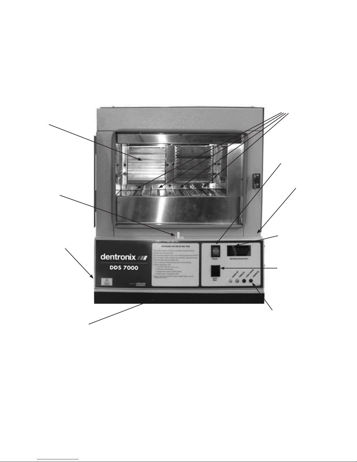
DDS 7000 UNIT OVERVIEW
Figure 1: Outside view of the DDS 7000
Louvers
Door Switch
COM
Port
Rack
Channels
Standby/On
Door Lock
Digital
Display
Cycle
Start Switch
Cycle
Indicator
Lights
Magnetic HEPA Filter Cover
1. 2. 3. 4.
7
DDS 7000 UNIT OVERVIEW
UNPACKING YOUR DDS 7000
Your DDS 7000 Dry Heat Sterilization System is delivered in two or more packages:
1. One large carton containing the DDS 7000 Dry Heat Sterilizer, Operating Instructions
and Accessory Kit.
2. One or more small cartons containing other accessories that may have been purchased.
WARNING!
This is a heavy piece of equipment. Please follow safe handling methods.
Examine each carton for any external damage. Be sure to check the corners of the box.
Immediately upon receipt open the large box, remove the protective packaging inserts and the sterilizer
from the carton. Carefully inspect the DDS 7000 for any damage.
Damage should be reported immediately to the transport carrier that delivered your unit as well as to the
Dentronix Sterilizer Repair Department 800-523-5944 (ext. 8925) or 330-916-8925 or e-mail tech@dentronix.
com or fax 330-645-8758.
CAUTION!
Read the Operating Instructions completely before operating the sterilizer
.
Set-up your DDS 7000 Sterilizer in a dry location according to the directions in the Operating
Instructions. Run your unit through a complete cycle with an empty chamber.
WARNING!
This is a heavy piece of equipment (96 pounds/43.64 Kg). Please make sure the counter
top will safely support the weight.
NOTE: RETAIN PACKAGING MATERIALS FOR FUTURE SHIPPING. The DDS 7000 should be
serviced by a professional on an annual basis, or when two consecutive spore strip test results
come back positive.
SERIAL NUMBER LABELS
Before proceeding further, check the specication label on the sides of the DDS 7000 to obtain
important information regarding model number, serial number and power requirements. Make
sure that this unit matches the power capabilities in your oce regarding voltage, amperage
and cycles. Record the serial number for future reference. (See Introduction Section, Page 4)

8
SELECTING YOUR STERILIZATION AREA
This is a heavy piece of equipment. Please make sure the counter top will safely support the weight. Locate
your sterilizer in an area that is clean and dry with easy access to patient treatment areas. Utilizing extra
counter space, in close proximity to your cleaning area, will make instrument processing smooth and orga-
nized. When placing your unit on the counter, do not push the exhaust stack against the wall. Leave a minimum
of 1”(2.54 cm) back clearance between the exhaust stack and wall to prevent heat damage to building materi-
als. Leave at least 4”(10.2 cm) side clearance between cabinets and walls to allow unrestricted passage
of cool down intake air. Failure to allow a four-inch side clearance could result in a considerably longer cool
down cycle and may result in an error message. For direct venting, the minimum clearance is 12” (30.5cm)
from top of unit to allow hot exhaust air to exit. The optimum clearance is 36” (91 cm) When building the DDS
7000 into a cabinet system, maintain a minimum of 4” (10.2 cm) clearance around the entire unit and use vent
adaptors DAD-UL or DAD-BL.
Exhaust stack of DDS 7000 - It is important to leave 4-inches around the sides of the unit and
12-inches above the top of the unit to maintain proper airow during the cool down cycle.
Exhaust Stack
Figure 2
8
9
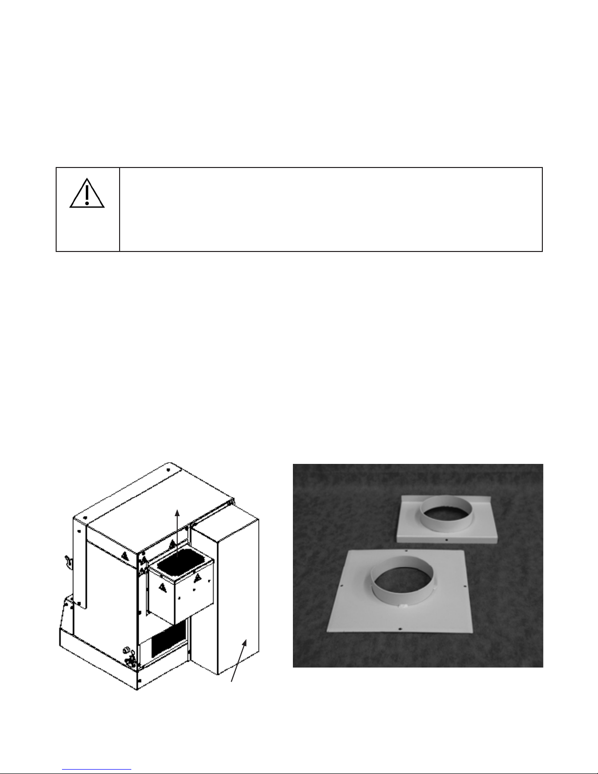
VENTING
Standard mounting of the exhaust stack positions the opening of the stack pointing up (see Figure
3), or to the left when facing the back of the unit. CAUTION: Never point the stack opening down
towards the fan (unless a DAD-UL vent adapter is used with a exible metal duct). To mount the
exhaust stack remove the three screws corresponding to the exhaust stack mounting holes in the back
of the sterilizer surrounding the exhaust opening (the opening with the exposed louvers). Place the
stack in position and secure with screws.
CAUTION
CAUTION: Do not remove cooling duct for any reason (See Figure 3)
Venting is recommended under the following conditions:
a) Installation of the DDS 7000 in a small room less than 12’ x 12’
(3.66m x 3.66m).
b) Installation of the DDS 7000 under cabinets or built into cabinets.
Two styles of vent adapters are available: (See Figure 4 Below)
Type DAD-UL – attaches to the exhaust stack allowing additional venting options – converts 5” x 7”
(12.7cm x 17.8cm) rectangular exhaust port to a 4” (10.2cm) diameter round ange.
Type DAD-BL – replaces the exhaust stack allowing vent connection directly to back of unit.
Both adapters utilize a 4” (10.2cm) diameter round duct. Metal or foil ducting material must be used. Vent
adapters can be used on vent runs of up to 6-8 ft (1.8m-2.4m). If your vent pipe is longer, sucient
back pressure will be created in the airow path reducing your unit’s cooling eciency, resulting in extended
cycle times and possible E-19 error codes.
Figure 4
Figure 3
Exhaust Air
Cooling Duct
DAD-BL
DAD-UL

10
CONNECTING TO A POWER SOURCE
Connect the DDS 7000 to a grounded power source in compliance with the specication label on the
side of the unit.
115V: Sterilizers used in the U.S. and Canada require a 15-amp, 115-volt grounded receptacle and operate at
50/60 Hz. A dedicated circuit is recommended. Other high-powered equipment (such as lathes, trimmers, X-ray
equipment) should not be placed on the same circuit.
CAUTION!
Do not install more than one DDS 7000 Sterilizer in a single circuit.
230V: Sterilizers require a 10-amp minimum 230V receptacle and operate at 50/60 Hz.
STERILIZER CONTROLS
The DDS 7000 is an automatic sterilizing system. Sterilization time and temperature have been pre-set
at the factory providing for optimum performance.
1) Standby/On switch – push the top of the switch to the “ON” position to activate all electrical
control circuits. Push the bottom of the switch to deactivate all electrical control circuits. If the switch
is switched to the Standby position during warm-up, sterilization or cool down cycles, an error code
will be displayed. This switch does not actually break incoming power. That can only be accomplished
by unplugging the device.
2) Cycle Start switch – depress the top of this switch in order to initiate the sterilization cycle.
Figure 5: Control Panel for DDS 7000.

11
INDICATOR LED LIGHTS
The control panel of your DDS 7000 is equipped with four (4) indicator lamps to monitor progress of
the sterilization cycle.
1) Warm-up – this Yellow LED will illuminate after pressing the“Cycle
Start”switch. It indicates heating element activation to raise instrument
load to sterilizing temperature of 374°F (190°C). The warm up time is load
sensitive and will vary based on the load density.
2) Sterilize – this Amber/Orange LED indicates that the temperature controller
has sensed a load temperature of 374°F (190°C) and has started the 3-minute
sterilizing phase. During this phase, the heating element will cycle on and
o to maintain an even temperature in the chamber. This LED
will turn o at the beginning of the Cool Down phase.
3) Cool Down – this Blue LED will illuminate during the Cool Down phase.
In this phase, cool air is drawn into the unit through a HEPA
lter. The LED will stay lit until instruments reach a safe handling temperature.
4) Cycle Complete – this Green LED will illuminate at the completion
of the cool down phase and indicates that instruments are sterilized
and ready to unload. It is also your indication that the DDS 7000
has completed the sterilization process. An audible tone will
signal the completion of the cycle. The door must be opened, to turn
this LED o and to allow unit to begin a new cycle.
WARNING!
DO NOT UNLOAD INSTRUMENTS UNLESS THE “CYCLE COMPLETE” LIGHT IS ON.
NOTE: The indicator LIGHTS will ash when a problem is detected during a cycle.
Refer to APPENDIX II for error code explanations.
DIGITAL TEMPERATURE DISPLAY
An LED display on the right-hand side of the control panel monitors sterilizing chamber/load
temperature in degrees Fahrenheit or Celsius. This display is activated when the “Standby/
On” switch is in the “On” position. User options and error codes will also display in this area.
DOOR LATCH
Turning the handle clockwise unlocks the door and allows it to swing open. To close, push the
door gently against the rubber door gasket and turn the knob counter – clockwise to engage
the cam lock, which pulls the door against the gasket, sealing the chamber.

12
SAFETY DOOR INTERLOCK
Your DDS 7000 is equipped with a cut-o switch beneath the door. (see Page 6) This switch
prevents the sterilization cycle from starting whenever the door is not properly closed. This switch also
interrupts the cycle if the door is opened during any cycle.
WARNING!
DISABLING THE DOOR LOCK AND OPENING THE DOOR AT ANY TIME DURING THE CYCLE PRI-
OR TO “CYCLE COMPLETE” MAY EXPOSE OPERATOR TO DANGEROUSLY HOT INSTRUMENTS.
DO NOT ATTEMPT TO REMOVE THESE INSTRUMENTS WITHOUT SUFFICIENT PROTECTION.
The DDS 7000 has an additional safety door lock mechanism, which prevents the door from open-
ing until the chamber temperature is at a “safe handling temperature”. In the event of an emergency,
requiring access to the chamber during any cycle, press and hold down the “cycle start” switch for 5
seconds. The door safety lock mechanism will unlock temporarily for a few seconds allowing access.
NOTE WARNING ABOVE: An Error Code will display notifying the operator of an interruption. Toggling
the “Standby/On” switch from “On” to “Standby” then back to “On” will clear the error message. To
restart the cycle, press “Cycle Start”. The DDS 7000 will rst cool down and then restart the complete
cycle from the beginning.
FIRST TIME USE CYCLE TEST
After the sterilizer is connected to a properly rated and grounded outlet (see page 10) follow the opera-
tion procedures found on pages 17-19 with an EMPTY CHAMBER.
Make sure that air is blowing out of the exhaust stack during the cool down phase.
WARNING!
The dry air may be hot 265˚F (129˚C).
STERILIZING YOUR INSTRUMENTS
What CAN be sterilized in the DDS 7000?
All metal instruments can be safely processed – stainless steel, aluminum, chrome and nickel-plated,
silver-brazed components and some high temperature plastics.
What CANNOT be sterilized in the DDS 7000?
Bagged instruments, cassettes, vinyl, rubber and plastic items, paper products, soldered components
(such as some impression trays, boley gauges, some band pushers), petroleum-based lubricants, and
any materials not capable of withstanding 420°F (215°C).
12
13
CAUTION!
ITEMS THAT ARE LABELED “AUTOCLAVABLE” ARE NOT NECESSARILY DRY HEAT STERILIZ-
ABLE. IF IN DOUBT ABOUT SPECIFIC PRODUCTS, CONTACT THE MANUFACTURER.
CAUTION!
REMOVE ALL VINYL GRIPS FROM PLIERS BEFORE STERILIZING.
14
INSTRUMENT HANDLING
The most important guideline in any sterilization procedure is:
STERILIZE ONLY CLEAN INSTRUMENTS!
Pre-cleaning is essential with any sterilization process because the elevated temperatures of the sterilization cycle will
bake on any residual materials or debris. The most eective and thorough method of cleaning is to use an Ultrason-
ic Cleaning Unit (such as the Dentronix DDUS60 Ultrasonic Cleaner). Non-Ionic multi-purpose cleaning concentrates,
which include a rust inhibitor and require no rinsing (such as Dentronix MP-US Plus), are highly eective for the process-
ing of orthodontic pliers. Ultrasonic cleaning will remove dirt, debris and old lubricants, which could cause discoloration
and stiening of joints. Weekly lubrication of the plier joint with a pure silicone product (such as Dentronix DSL-16 or
DSY-20) will maintain smooth joint travel.
WARNING!
If instruments are dropped, sprayed, or mishandled after sterilization, the instruments must
be pre-cleaned as recommended above. Never return the items to the sterilizer without rst
cleaning them.
WARNING!
DO NOT USE ANY OF THE FOLLOWING:
• DO NOT USE IODOPHORS TO CLEAN PLIERS PRIOR TO STERILIZATION
• DO NOT USE ALCOHOL TO CLEAN PLIERS OR TO DISPLACE MOISTURE PRIOR TO STERIL-
IZATION
• DO NOT USE ANY CLEANER WHICH LEAVES A RESIDUE. THIS MAY RESULT IN SMOKING
OR UNDESIRED FUMES DURING THE STERILIZATION CYCLE.
• DO NOT USE PLAIN SOAP AND WATER TO CLEAN PLIERS PRIOR TO STERILIZATION.
• DO NOT DIP PLIERS IN ANY FLAMMABLE LIQUID PRIOR TO LOADING IN STERILIZER.
• DO NOT LUBRICATE PLIERS OR INSTRUMENTS WITH PETROLEUM-BASED LUBRICANTS.
• DO NOT USE WITH CASSETTES OR INSTRUMENT BAGS
• DO NOT LOAD INSTRUMENTS ON THE BOTTOM OF THE CHAMBER OR BETWEEN THE
PLIER RACKS. FOR INSTRUMENTS THAT DO NOT FIT THE RACKS AS SHOWN, USE HORI-
ZONTAL TRAY CAT. NO. D5000S-T OR HALF TRAY CAT. NO. D5000S-HT.
• DO NOT PLACE ANY ITEMS BELOW THE TRAY OR SHELF UNITS TO BE STERILIZED.
• DO NOT PLACE ANY INSTRUMENTS INSIDE THE PLIER RACKS.
15
PLIER RACKS
The four anodized plier racks that are supplied with your DDS 7000 are manufactured from aluminum for optimum heat
transfer and to reduce weight. Also available are:
A) Mini Rack holds 4 pliers
B) Combo Rack holds 5 pliers plus 5 Mathieu Hemostats or other hand instruments.
C) Long Handle Combination Rack holds 2 Long Handle Pliers,
3 Regular Pliers, 5 Mathieu Hemostats or other hand instruments.
D) The plier racks supplied oer convenient transport to chairside.
WARNING!
The DDS 7000 has been tested and approved for use with Dentronix racks. Do not
use cassettes or other delivery systems as they may cause overheating or failure to
sterilize.
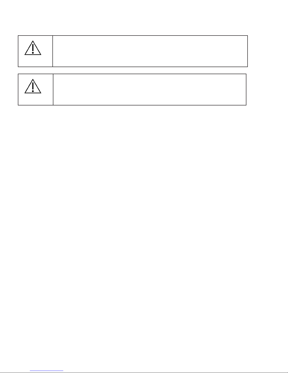
LOADING YOUR DDS 7000 PLIER RACKS
The eectiveness of Dry Heat is dependent on exposure of the instrument load to the convective properties of the
heated airow in the sterilization chamber. The DDS 7000 rack system was designed to provide a predictable location
and spacing for the instrument load so that optimum exposure can be achieved. Pliers should only be loaded in the
notches of the rack (see Figure 6). Never place instruments inside of plier racks. Doing so may impede air ow resulting in an
error code or failure to sterilize.
In addition to the plier racks, Dentronix also oers a Horizontal Tray (Part No. D5000S-T) and a Half Horizontal Tray (Part
No. D5000S-HT). These trays can be used for instruments that do not t onto the racks. These trays were specially de-
signed for use in a Dry Heat Sterilizer. The half tray allows the user to sterilize single-handled instruments along with two
full racks of pliers. Use of trays other than the D5000S-T and D5000S-HT will impede the airow around the instruments
and will result in failure to sterilize the instruments.
Figure 6
Correct and Incorrect placement of racks in DDS 7000. Note: The incorrectly placed rack is not over the air vents of the
rack channel, whereas the correctly placed rack is.
WRONG
Incorrect
Rack
Placement
Correct Rack
Placement

16
Table 1 describes the maximum loading for each possible combination of racks and/or trays. It is important for
good sterilization practices not to add more instruments than outlined above. Doing so may impede the ow of
air around some of the pliers and may cause overheating or a failure to sterilize all the instruments. Sterility is not
guaranteed when the chamber is improperly loaded. When loading a rack to less than full capacity, distribute the
load evenly over the full length of the rack (below).
Figure 7: Rack Loading
CAUTION!
Never load instruments on the bottom of the chamber or between the plier racks. For instruments
that do not t the racks as shown, use Horizontal Tray Cat. No. D5000S-T or HalfTray Cat. No. D5000S-
HT. Never place any items below the Tray units to be sterilized. Never Use Cassettes in the DDS 7000.
Loading Scenario Maximum Loadings
Racks Only Four (4) Plier Racks capable of holding nine (9) orthodontic pliers
each for a total of thirty-six (36) pliers or two (2) plier racks holding
nine (9) orthodontic pliers each for a total of eighteen (18) and two (2)
combo racks each holding ve (5) Mathieu Hemostats or other hand
instruments.
Full Tray Only One (1) Horizontal Tray capable of holding up to six (6) orthodontic
pliers or up to (12) single-handle hand instruments. Other combinations
can include: (5) orthodontic pliers with up to (2) single-handle hand
instruments; (4) orthodontic pliers with up to (4) single-handle hand
instruments; (3) orthodontic pliers with up to (6) single-handle hand
instruments. (2) orthodontic pliers with up to (8) single-handle hand
instruments. (1) orthodontic plier with up to (10) single-handle hand
instruments.
Half Tray and Racks Two (2) Plier Racks capable of holding nine (9) pliers each for a total
of eighteen (18) pliers or two (2) combo racks each holding ve (5)
orthodontic pliers and three (3) Mathieu Hemostats and three (3)
single ended hand instruments along with one of the following tray
congurations: one (1) Half Tray capable of holding three (3) orthodontic
pliers or six (6) single-handle hand instruments; or one (1) Half Tray
capable of holding two (2) orthodontic pliers with up to two (2) single-
handle hand instruments; or one (1) Half Tray capable of holding one (1)
orthodontic plier with up to four (4) single-handle hand instruments.
Table 1: Maximum loading for the DDS 7000
Right Way to Load Wrong Way to Load
17
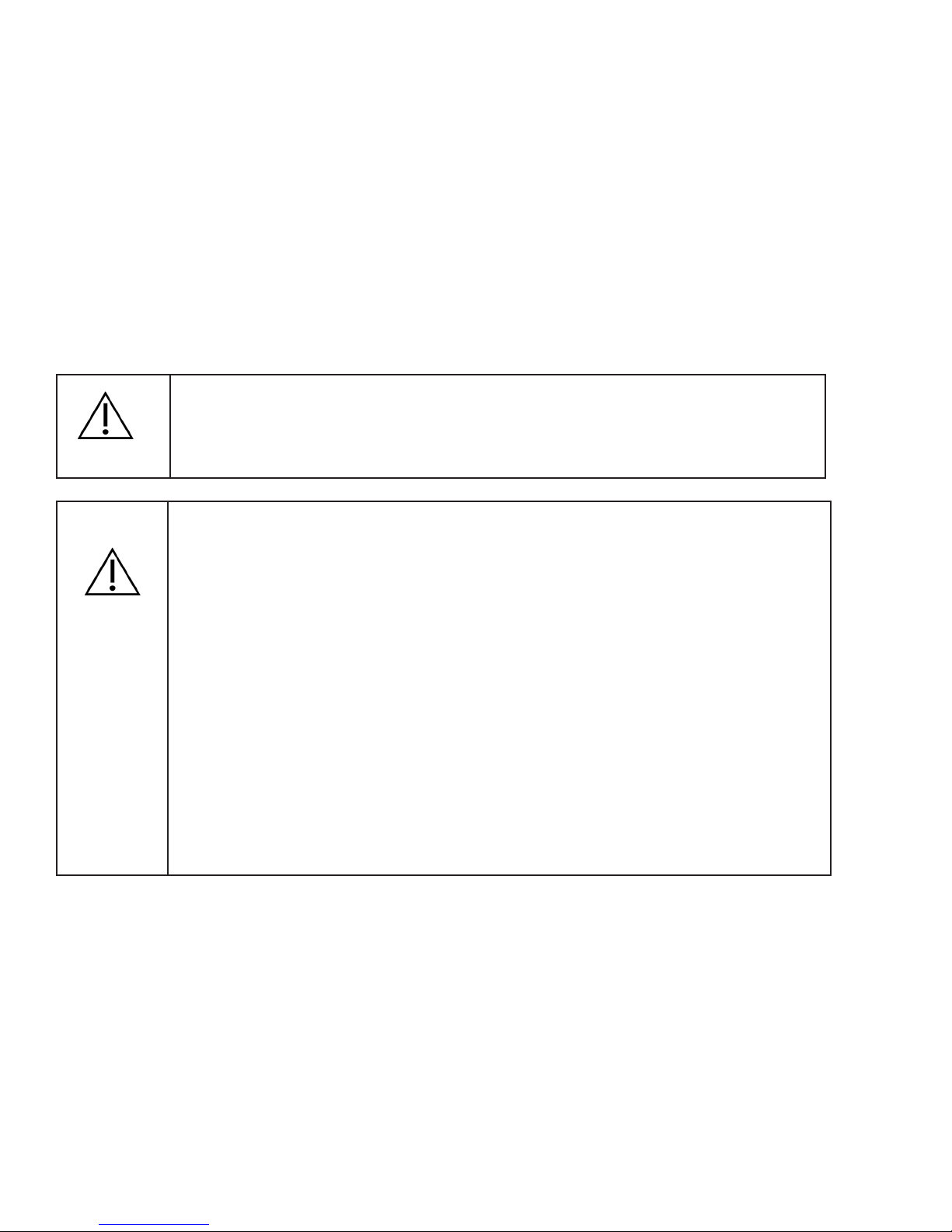
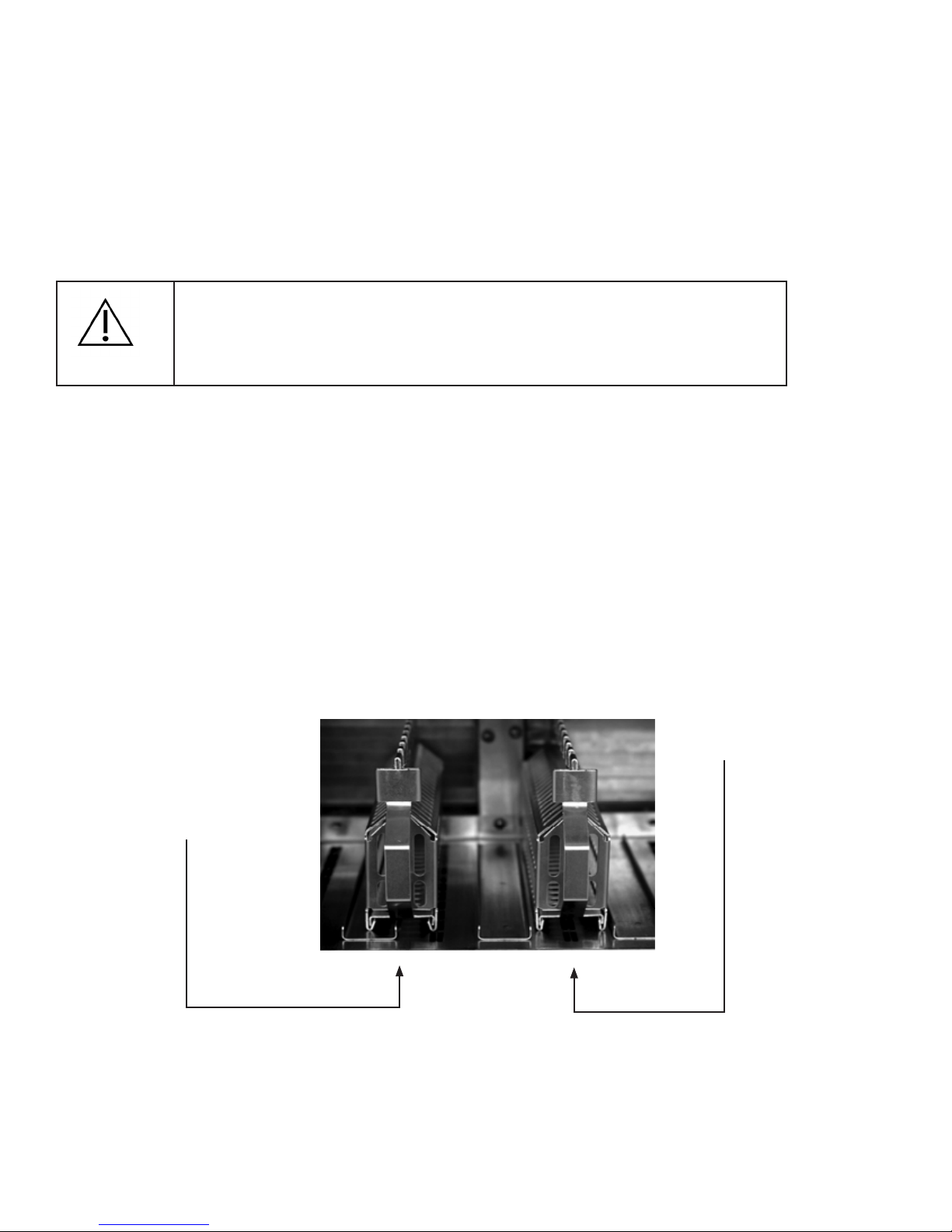
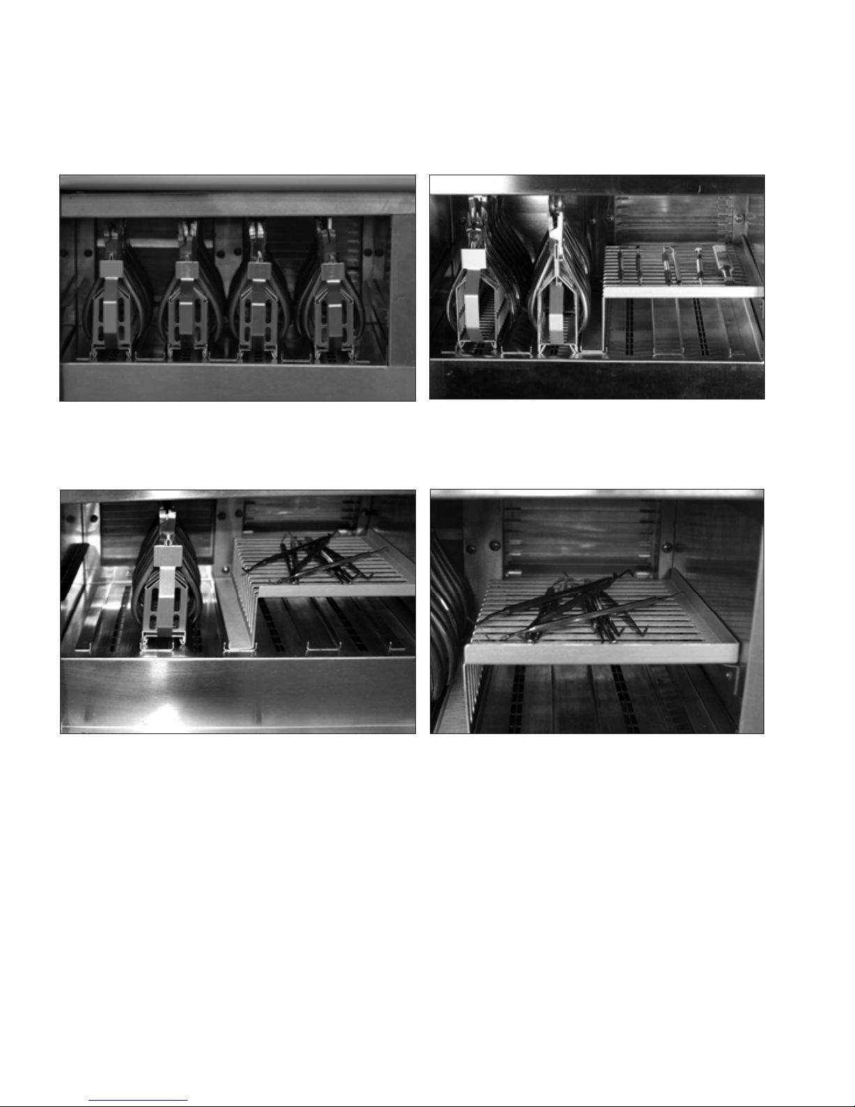
LOADING THE STERILIZATION CHAMBER
Example of proper and improper loadings
Figure 7A: Properly Loaded DDS 7000 with Figure 7B: Properly Loaded DDS 7000
four Plier Racks. with Half-Tray and two Plier Racks.
Figure 7C: Improperly loaded Half Tray with Figure7D: Close up of improperly loaded
Plier Rack. The Plier Rack is not in the proper half tray. Instruments should be placed so
rack channel and covers the air vents. This that they do not touch one another or extend
will impede airow around the instruments. over the tray periphery.
ALSO AVAILABLE: FULL TRAY FOR HAND INSTRUMENTS.

18
OPERATION
Once the DDS 7000 is loaded, it is time to begin the sterilization process. Close the door by gently
pushing the door against the rubber door gasket and turning the knob counter-clockwise. This will
engage the cam lock, which pulls the door against the gasket, sealing the chamber.
Figure 8A Figure 8B
Depress the“Standby/On”switch to“On”. The Standby/On switch activates the control panel. The display
shows ambient temperature. No LEDs are lit at this time. Press the Cycle Start switch to initiate a cycle. The
cycle is preprogrammed and cannot be altered by the user.
Figure 8C Figure 8D
Once the “Cycle Start” switch is pressed, the “warm up” LED lights up indicating that the DDS 7000 is
in the warm-up phase of the cycle.
The Safety Door Interlock engages as chamber exceeds 122ºF (50ºC). The lock activation is
indicated by a dot that appears in the lower right corner of the display. The device will
continue warm-up until the set point is reached. The time required for warm-up is
dependent on the size of the load.
73°F
73°F 124°F
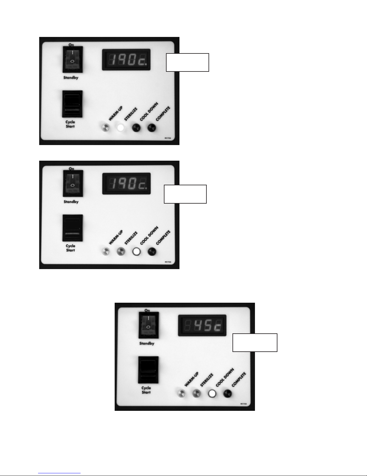
19
The DDS 7000 is programmed to sterilize for three (3) minutes. At the completion of three (3) minutes,
the DDS 7000 automatically begins the cool down phase of the cycle. The blue “Cool Down” LED is lit.
Cool down is achieved by forcing ambient ltered air across the load and expelling the heated air.
The door interlock disengages at 113ºF (45ºC) and the indicator dot disappears from the lower right
of the display.
Once the operating temperature of
374ºF (190ºC) is reached, the DDS 7000
begins the sterilize (exposure) phase.
The amber “Sterilize” LED lights up.
During this phase, the internal temperature
is closely monitored and controlled. The
temperature on the display is the
temperature of the air as measured
after it has left the chamber. The
displayed temperatures during this
phase are typically between 368 - 376ºF
(187 – 191ºC). If the display tempera-
ture ever drops below 365ºF (185ºC), the
cycle will fail.
374°F
374°F
113°F
Figure 9
Figure 10
Figure 11

20
Once cool down is complete @ 104˚F (40˚C), the green “complete”LED lights up indicating that it is now safe to
remove the sterilized tools from the chamber (ABOVE).
WARNING!
DO NOT UNLOAD INSTRUMENTS UNLESS THE “CYCLE COMPLETE” LIGHT IS ON.
NOTE: The indicator lights will ash if there was a problem during any phase of the cycle. Refer to APPENDIX
II for error code explanations.
During cool down, the fan is drawing air through the HEPA Filter and into the chamber to cool the in-
struments. An audible tone will signal the completion of the cycle. The door must be opened to turn
this LED o and to begin a new cycle. If instruments are not immediately removed from the oven cham-
ber, they may reheat slightly from warm areas inside the chamber.
SPECIAL NOTE ON MOUTH MIRRORS
The DDS 7000 has been tested to safely sterilize good quality metal mouth mirrors. However,
depending on the age of your mirrors and their exposure to chemical disinfectants and cleaning
solutions, there may be moisture leakage behind the glass. This moisture will vaporize during the ster-
ilization cycle and cause shattering of the mirror. When sterilizing mirrors, wrap them in aluminum foil
to contain any glass fragments that may occur.
For best results, wipe mirror faces with a clean cloth after ultrasonic cleaning and before sterilization
to prevent fogging.
104°F
Figure 12
Table of contents
Popular Laboratory Equipment manuals by other brands


Hydro systems
Hydro systems HydroChem 912 quick start guide

THORLABS
THORLABS OCTG Series user manual

Holland Green Science
Holland Green Science 10301001 user manual

Bungard
Bungard Compacta L30 Instructions for use

Fisher Scientific
Fisher Scientific Fisherbrand Isotemp RT AVCD HPS Advanced Operation manual

SCHOTT
SCHOTT EasyLED Spotlight Plus user manual


