NERI SNR-BD User manual

1
Portable Plasma / Flame CNC Cutting
Machine
USER MANUAL
SNR-BD
Neri Machine Tools Pvt Ltd.
www.nerigroup.in
www.EngineeringBooksPdf.com

2
WE THANK YOU VERY MUCH FOR YOUR INTEREST SHOWN
IN OUR PRODUCT.
Before using this machine, please read the instruction carefully.
1. Open the package, please check the center unit, make sure it is not be
broken, and make sure the packing list conform to the article.
2. Please make the voltage is(AC220V±10%, and use the isolation
transformer or other isolation voltage regulator device to make sure
the system work stably. The machine must be grounded reliably when
it is working.
3. Clean up dust on a regular basis to ensure the rail and rack clean.
4. The display screen of CNC system is easily broken, pay attention to
protect it.
5. This machine should be operated by professional, with some operation
and safety train information.
6. If there is something unclear, please contact with the local dealer or
call the manufactures.
Content
1 Machinery part--------------------------------------------------------------------3
2 CNC control system part---------------------------------------------------------8
www.EngineeringBooksPdf.com
3
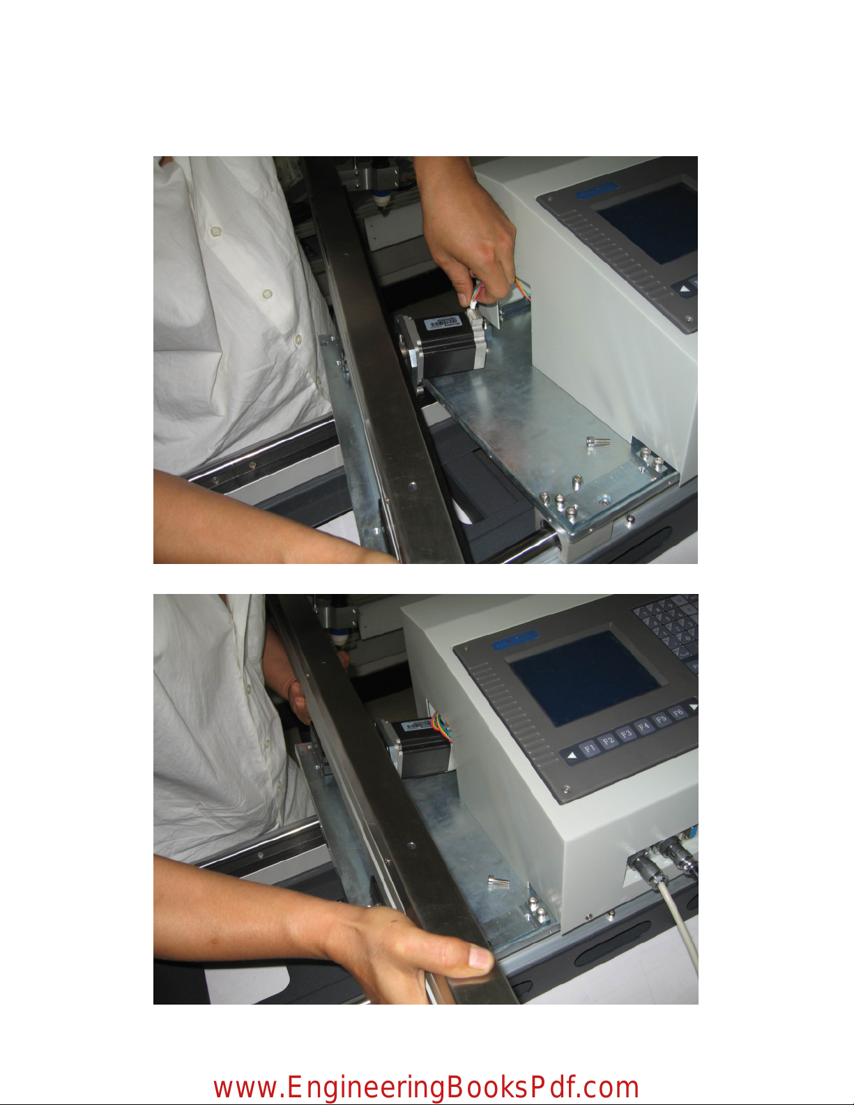
Machinery Part
1 Put the crossed beam on the center unit, connect the line with the motor.
2. put the motor into the center unit.
www.EngineeringBooksPdf.com

4
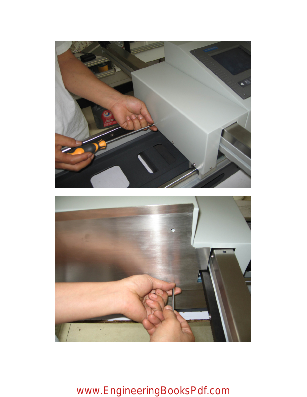
3. Fix the four screws.
4. Put the security cover on the beam.
www.EngineeringBooksPdf.com
5
5. Fixed the screw of the security cover.
6.Install the anti-fire plate.
www.EngineeringBooksPdf.com
6
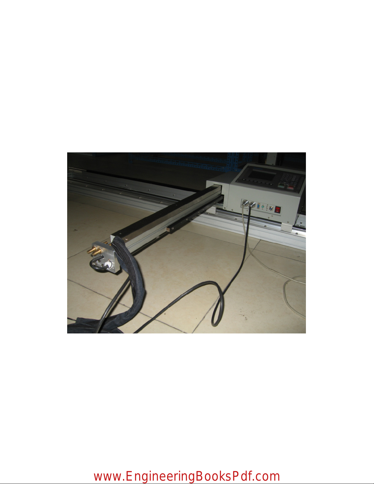
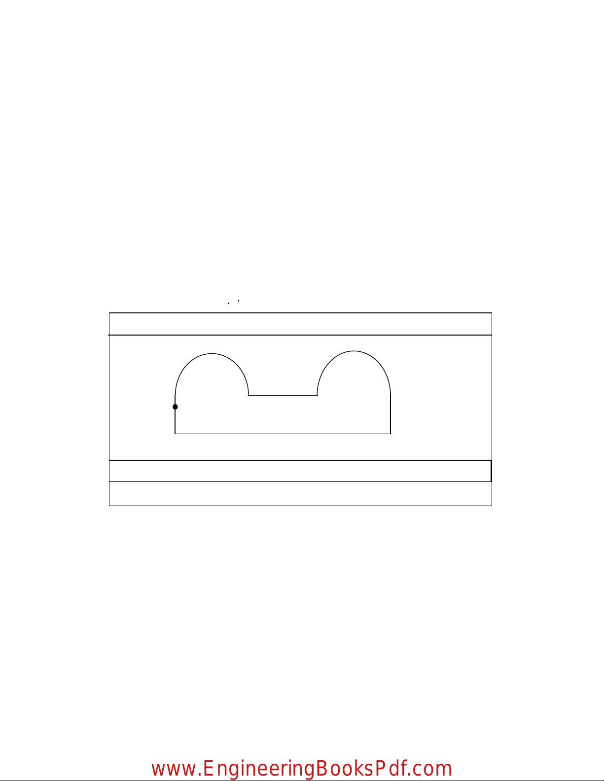
How to use the special crossed beam trunkings?
①Loosen the screw, remove the anti-fire plate.
②Take the security cover from the center unit.
③Loosen the screw of the trunking, take it out, put the plasma cable into the trunking, and cover
it. Then install security cover and the anti-fire plate as following picture.
www.EngineeringBooksPdf.com

7
Ports details
Parameter
Input voltage 220V
Power frequently 50HZ
Rated power 180W
Display 5.7 inch
Effective cutting range X-axis: 2000mm Y-axis: 1200mm
Speed Flame cutting: 0-1000mm/min unload>8m
Plasma cutting: 0-4000mm/min unload>8m
Cutting thickness Flame cutting: 0-150mm
Plasma cutting: 6-150mm
Transversal beam length (Y-axis) 1500mm
Longitudinal rails frame (X-axis) 2500mm
Total weight 80Kg
Gas depression Max 0.1Mpa
Oxygen depression Max 1.5Mpa
Befitting gas Ethane, propane, methane
www.EngineeringBooksPdf.com

8
CNC system part
Chapter One Summarize
1.1 System features
1) 5.7 high-definition lattice LCD, Small volume, Structure compact.
2) Processing graphics dynamic/static display.
3) High speed 16-bit and 8-bit single-chip microcomputer and hardware interpolator
control. High speed running by 0.5μequivalent 6 meters/minute.
4) Step motor high subdivision control the driver,move smoothly, low noise, the quality
improved clearly.
5) You can set begin speed and the time of rising/falling arbitrarily.
6) Supplying multiple constant loops to program simply.
7) Directly diagnose all input information of system, Convenience for you to check.
8) Multi-settings of parameter, can suit different requires.
1.2 Technology norm
1) Pulse equivalent:X-axis 0.5μ(diameter)Z-axis 1μ(or X axis 0.25μdiameter)
Z-axis 0.5μ)
2) G00 Max-speed:≥6 meter/minute(X-axis 0.25μ(diameter)Z-axis 0.5μ)
3) Number of connected shaft:2 axis
4) Input coordinate scope: +/- 9999。999mm
5) Maximum lines of user program: 540 line
6) User program space: 60K
7) Number of user program:64
8) Dimension:300*200*85
www.EngineeringBooksPdf.com

9
Chapter Two System Operation and Function
2
22
2.1 Operate panel keyboard illustration
`
【F1】-【F6】Function keys: Under different operate mode, they have different definition.
【 】,【 】Triangle sign Give up and quit:Definition of the left and right key is
same.
6
3
T
。
7
8
9
U
4
V
5
I
1
J
2
M
—
S
0
G
X
Y
F
R
H
N
L
D
-
INS
DEL
S
↓
Pgup
Pgdn
S
↑
www.EngineeringBooksPdf.com
10
【INS】:Insert key under program state. Under others, it is used for increasing LCD brightness.
【DEL】:Delete key under program state. Under others, it is used for decreasing LCD brightness.
【Pgup/ S↑】:Page-up key under program state. Under automatic and manual function, it is used
for adjust cutting-gun, when press/loosen the key, cutting-gun rising/stopping.
【Pgdn/ S↓】: Page-down key under program state. Under automatic and manual function, it is used
for adjust cutting-gun, when press/loosen the key, cutting-gun falling/stopping.
【Shift】∶Space key. It is used for distinguish between upper case and lower case under program
editing state.
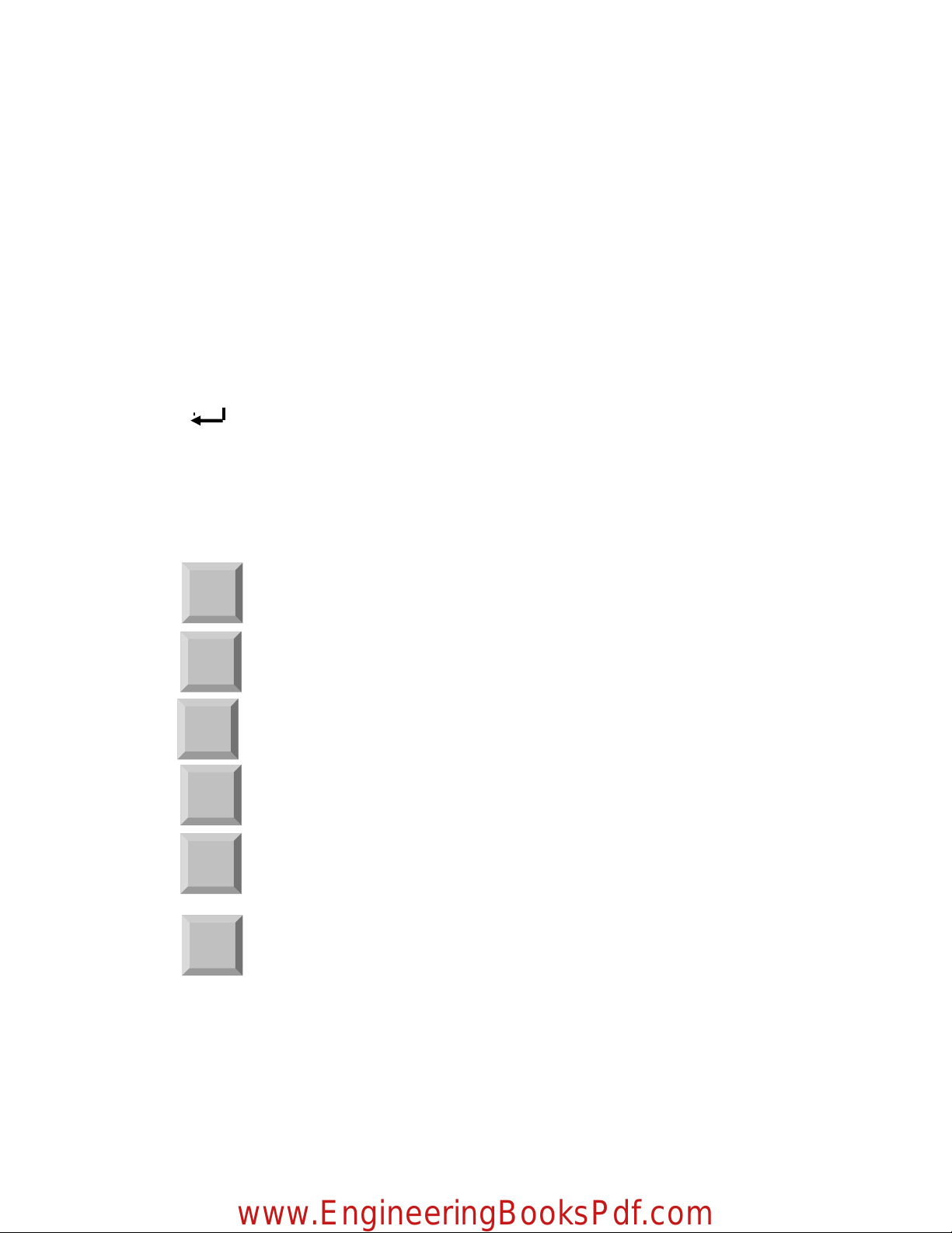
【 】:Enter/Effective key
【F↑】:It is used for increase speed under automatic and manual control state, increase 1%/press once
【F↓】:It is used for decrease speed under automatic and manual control state, decrease 1%/press once
Strong current control :
Ignition automatically key under manual control state.
Strong current control :
Preheat oxygen key under manual control state
Strong current control :
Acetylene open key under manual control state
Strong current control :
Cutting oxygen key under manual control state
Strong current control :
Perforation key under manual control state
Strong current control :
Close all states under automatic and manual control state
Acetylene
opened
Ignition
Preheat
oxygen
Cutting
oxygen
Perforation
General
switches
www.EngineeringBooksPdf.com

11
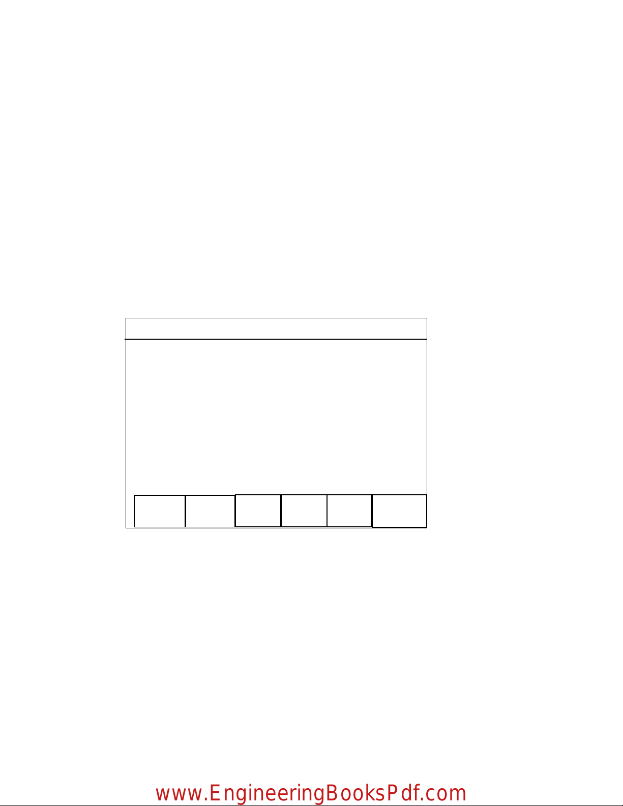
2.2 Main interface of system working
After power on,enter into main interface,please press【F1】—【F6】key and select function as
follow:
【F1】Auto:Machining program automatically.
【F2】Manual: Manual adjusting the position of lathe.
【F3】Editor:Edit/modify machining program
【F4】Parameter:Parameter setting
【F5】Diagnosis:Checking input/output information of lathe.
【F6】Return:Lathe return to origin(the position set by proximity switch)
Press【G】【G】【3】key,System will clear all contents of user program..
CNC Flame cutting Machine system
Automatic Manual Editor Parameter Diagnosis Return
www.EngineeringBooksPdf.com

12
2.3 Auto function
Under main interface ,press【F1】key, System will enter into auto function and display as follow:
*The first line display : F×〈magnification〉%=〈current speed〉,current program name and the
number of machining.
*The medium display the current coordinate of X and Y by big character.
*Under the coordinate the two lines are current continuous program, use ‘►’ indication.
*Above line of the right indicate the state is automatic machining.
*Under line of the right,indicate current system state respectively,including :Acetylene(switch),
Preheat oxygen(switch),Cutting oxygen(switch),Cutting tip(rising/falling/stopping).
*Others indication:
M—Latest instruction M.
U,V—Increment coordinate.
Speed:F* 100%=00000 Program:0001 Number:0000
Single segment Manual Free play Graphics Select segment
Return reference
point
X +0000。000
U +0000.000
V +0000.000
Preheat:0850
►G92 X100YZ0
G00 Y100
Machining
automatically
Acetylene closed
Preheat closed
Cutting closed
Cutting tip stop
www.EngineeringBooksPdf.com

13
Operate under automatic function
1.Press【F1】,System select single segment machining,Press 【F1】again, give up. Under
this state,Press【Startup】key once,System will run one instruction. Press【Quit】key,
give up this function.
2.Press【F2】,System enter into manual state, concrete function refer manual function section.
3.Press【F3】,System enter into free play state,Press【Startup】system working, display the
moving trace of cutting tip, But the operation of driver and I/O all closed to check whether
program is correct.
4. Press【F4】,System enter into graphics machining tracking state. (referring the picture below)
5.Press【F5】,System select arbitrary segment to machining,’►’ represent the first line
program that current running. Press【↑】and【↓】key ,you can select orderly the current
program. Press【Startup】,System will run from the selected program. Press【Quit】
will give up select segment machining. Attention: Under select segment machining state,
firstly, you should aim the cutting-gun to initiation position of program (easy aim). Press
【Startup】begin to select segment machining.When appear ‘Pause’ sign, you can manual
control the strong current switch to finish the prepare working, then press【Startup】,System
will begin to run from the selected segment.
6. Press【F6】,System will return automatically to reference point.
7. When lathes are not running, you can select strong current key to control Ignition, Acetylene
opened/closed,Preheat oxygen opened/closed, Cutting oxygen opened/closed and Cutting
tip rising/falling/stopping. Under normal machining state, the strong current keys are locked.
Attention: Press ignition key,if acetylene key is not open,please open acetylene valve
firstly ,then open ignition switch, after one ignition delay(refer Parameter-
--
-Control-
--
-
Ignition delay), close ignition switch. Press【K1】 key will run a preheat perforation
www.EngineeringBooksPdf.com
14
procedure.(refer M50 preheat perforation fixed cycle).Press【K2】key is general switch.
8. Press【F↑】and【F↓】,you can increase or decrease speed magnification. Note: Manual and
automatic magnification are saved respectively. The value immune to influence of power
on/off.
9.Press【Pgup/S↑】and【Pgdn/S↓】,This two keys are compound. Under edition state, they are
turn to page up and down.. Under this state they are used to control move up and down of
cutting tip. Press【Pgup/S↑】(or【Pgdn/S↓】)cutting tip moving up (or down),loose it
will stop.
Automatic graphics track
Under graphics mode, press【F】,the picture will double its size, Press【F】again,
come back. Press【↑】,【↓】,【→】,【←】key will move the display window,you can
observe every segment in detail.
10.Press【DEL】key to clear counter.
Speed: F*100%=0000 Program :0001 Number:0000
G92
×
500 Y200
X
:
0050.000 Y00200.000 M05
Preheat:
0850
www.EngineeringBooksPdf.com

15
Reference point under automatic machining
Reference point is initial point of machining program(set by G92).One program run once
(include free play), Reference point will be saved automatically(Also set by parameter).
Once reference point is set, orientation of reference point is very easy, as follows:
1)Please aim the knifepoint to special position of steel plate that waiting for cut(know
coordinate), set the current coordinate.
2)Under automatic or manual mode, if select return reference point function, system will
automatically return to reference point.
Startup under automatic machining
After all prepare work is ok, there are two means to startup the automatic machining program.
1.Press【Startup】.
2.Press outside“startup”button.(refer chapter 6.1 “outside input interface”)
Control and error compensate under automatic machining
After automatic machining beginning, only these keys are effect:
1.【Pause】: Press this , system will decrease speed till stop. Execute instruction M according to
the set of G61 to keep the current display contents. If press【Startup】, system will keep on running.
Under pause state, if find deviation of dimension, you can press【F2】key to enter into manual state
(in inch state automatically, increment is 0.01mm),Operator press direction key to adjust the
position of knifepoint, its move be considered compensation. Adjustment finished, press【Startup】
system will neglect compensation movement and keep on running according to before adjustment.
If press 【Quit】, system will return to main picture.
Error compensation under pause state is reference point’s compensation in fact.
2.【F↑】,【F↓】Moving axis adjust speed key: Increase or decrease speed magnification, change
1% once.
www.EngineeringBooksPdf.com

16
3.【Pgup/S↑】,【Pgdn/S↓】Control cutting gun rising or falling ,Press key, cutting gun rising
or falling, loose it will stop.
4.【Stop】:
::
:Outside button(refer chapter 6.1 “outside input interface”),Signal can derive
from input port. All stop when this key is effect.
Return and renew machining according to original track
During machining, because of cutting incompletely, need return and renew machining, You
can deal with as follow:
1.Press【Pause】, system will decrease speed till stop and display"pause"sign. Prompt
(Graphics mode)"F2manual F6return",Press【F2】can enter into manual compensation
function(refer below),press【F6】can enter into return and renew machining function.
If select【F6】, System will hint:
Return<-
<-<-
<-
->
->->
->forward
Indication: Press【←】, System will return along original trace. Press【→】, System will forward
along original trace base of return. During return, if reach position that want to return, You can
press【Pause】again, repeat the above-mentioned procedure, select again keep on returning or
forward.
2.You may press【Pause】again when system get to the return position,After system stop
Steady, you can press the strong current key correspondingly(like Preheat perforation, open
cutting oxygen etc.),Press【→】again, and select machining forward.
3.Above-mentioned operate can run repeatedly till get the satisfactory effect.
Break recover and power cut disposal
When system pause by man-made, it will save automatically the current working trace
(cutting tip’s position) as a break. This break will be saved forever, regardless power off. Power on
again or enter into automatic mode, if only the current program is not changed you can press【G】
key to resume break. When find the break, system will hint "pause"state, You can press the
strong current function key correspondingly (such as preheat perforation, open cutting oxygen
etc.), Press【Startup】again, system will keep on running from break’s position.
www.EngineeringBooksPdf.com
17
After machining pause, if you want to quit automatic state and enter into manual state to
move cutting tip(whatever how much),When press【G】key to begin resuming break, system will
move the cutting tip to the position of break firstly, then resume break. Of course, if you changed
the current coordinates by hand, the break will not be resumed normally.
If during machining, you encounter failure of electricity, you can enter into
automatic mode firstly after get back electric power. Press【F3】key will set the current
coordinate as break and recover like above-mentioned. Attention: This moment you must not move
the cutting tip or set the current coordinate.
Only pause operation can generate break.
2.4 Manual function
Under main picture, press【F2】enter into manual mode, display:
Display under manual function
Like automatic mode,but have any distinction:
1. Under left of the menu display the current increment value.
2. Under right hint:Press【G】, you can modify the inch increment.
3.Press【X】, you can modify the X value. Press【Y】, you can modify the Y value.
Speed: F×100%=0000 Program:0001 Number:0000
Preheat:0850
Inch increment:0001.000
Inch moving Manual Pulse
MDI
Return
parameter
Test position
X +00000.000
Y +00000.000
Manual operating
Acetylene closed
Preheat closed
Cutting closed
Cutting tip stop
M00
U 0000.000
V 0000.000
XY coordinate
G inch increment
www.EngineeringBooksPdf.com

18
Operate under manual function
1. Press【↑】and【↓】to adjust the position of X axis,Press direction- key correspondingly. The
X axis will run by speed
the maximum speed limit
the maximum speed limitthe maximum speed limit
the maximum speed limit
* Manual magnification. Press【→】and
【←】to adjust the position of Y axis. Press direction-key correspondingly, The Y axis will
run by speed
the maximum speed limit
the maximum speed limitthe maximum speed limit
the maximum speed limit
* Manual magnification.
2.Press【F1】, system will enter into inch moving state, Press the direction-key once, Motor will
move one inch increment correspondingly. Press【F1】again, return to continue state. Press
【G】key can change the inch increment.
3.Press【F2】,system will enter into manual pulse mode, display as follow:
4.Press【F4】,system will select MDI function,Under this mode,You can directly input single
segment program, such as:
G01 X100 Y200
After input one line, press【Enter】key to run at once. Press【Quit】key to cancel. MDI
MDI MDI
MDI
mode supports various G、M、S instructions. Note: The MDI instruction inputted will
be saved till modified or power off.
Speed:F×100%=0000 Program:0001 Number:0000
X axis Y axis
1.00
0.10
0.01
0.002
X +00000.000
Y +00000.000
Manual operating
Acetylene closed
Preheat closed
Cutting closed
Cutting tip stop
M05
U 0000.000
V 0000.000
XY coordinate
Enter into manual pulse mode,
Press【F1】and【F2】to select
X or Y axis.
Select valid weight:
【F3】- 1.00mm / pulse
【F4】- 0.10mm / pulse
【F5】- 0.01mm / pulse
【
】
www.EngineeringBooksPdf.com

19
5.Press【F5】,System will control cutting tip return to reference point.
6.Press【G】will change the value of inch increment, hint: input increment value, then press enter
key, this value will be saved till changed or power off.
7.Press【X】key to change value of X .hint: input coordinate of X(Y)axis, then press enter key,
the coordinate of X and Y are changed at once; Press【Y】key to change value of Y .hint: input
coordinate of Y axis, then press enter key, the coordinate of Y are changed at once
8.Press【F6】key,system enters into test-position function. Test-position is testing the precision
distance from the current position of cutting tip to the origin of machine tool. Concrete usage:
Firstly, You should aim the cutting tip to a special point(such as reference point),test the
current coordinate and modified(press“X/Y”),Press【F6】key, cutting tip begin to return to
origin of machine tool and save it as machine’s origin of parameter. Return-position is same to
test-position from shape, but their results are not same: Return-position is that send the origin
value of machine tool to current coordinates , but test-position is that send the current
coordinate to origin of machine tool.
9.Press【F↑】and【F↓】,you can adjust the manual magnification. Note: Manual and automatic
magnification are saved respectively till changed and the value immune to influence of power
off.
10.Press【Pgup/S↑】,【Pgdn/S↓】and strong-current key ,their usage is same to
auto mode.
2.5 Parameter set
Under main working picture, Press【F4】can enter into parameter set function.
Displaying:
Parameter set
Speed Adjustment Control System Save
www.EngineeringBooksPdf.com

20
Every function item save parameter as follow:
Speed---- Start speed,Adjust time,Max speed.
Adjustment---- Software limit position,Origin,reverse clearance,reference point
Control
ControlControl
Control----Machining speed limit, Ignition delay, Preheat delay, Cutting gun rising delay,
Cutting gun falling delay, Perforation cutting gun rising delay, Perforation cutting gun falling
delay.
System----Each axis’s electric gear, Driver’s subdivision.
Save----Save the changed parameters to parameter area.
2.5.1 Speed parameter
Press【F2】and select (refer picture below)
2.5.2 Adjust parameter
Press【F3】and select adjust parameters(refer picture below),Among these :
Speed parameter setting
Start speed:X 00250 Y 00250
Adjust time:X 00040 Y 00040
Max speed limit:X 05000 Y 05000
Note
:
time
’
s unit
is one percent second
Cutter Speed Adjust Control System Save
Speed
Tim
e
Start speed
Adjust time Adjust time
Max speed
Start speed
Means of each parameter refer left
picture:
Start speed and max speed ‘s unit
is mm/minute
time’s unit is one percent second
00040 express 0.4 second.
The max speed limit regulate the
max speed of by-hand and G00。
www.EngineeringBooksPdf.com
Table of contents
Popular Welding System manuals by other brands


Hypertherm
Hypertherm Powermax 30 Service manual

Lincoln Electric
Lincoln Electric RANGER 305LPG IM10043-A Operator's manual

ESAB
ESAB EAS IV instruction manual

MasterCraft
MasterCraft MIG instruction manual

Miller Electric
Miller Electric Subarc DC 650 Specification sheet

Unitor
Unitor UWI 230 TP AC/DC instruction manual

Chicago Electric
Chicago Electric 96712 Owner's manual & safety instructions

Thermal Arc
Thermal Arc 161 S operating manual

Lincoln Electric
Lincoln Electric RANGER IM10030 Operator's manual

Snap-On
Snap-On TIG 250 AC-DC Service manual

Klimawent
Klimawent SLOT 1600 user manual

Sealey
Sealey IMIG160.V2 quick start guide