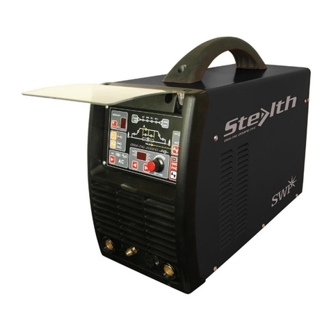
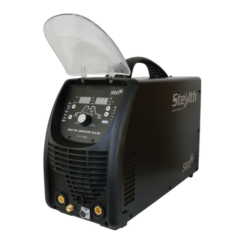
Stealth 9000H User manual

Part No. 9000H
DIGI-MIG 200
OPERATOR’S
MANUAL

STEALTH DIGI-MIG 200
IMPORTANT
Read this Owner’s Manual completely before attempting to use this equipment.
Save this manual and keep it handy for quick reference. Pay particular attention
to the safety instructions provided for your protection. Contact your distributor if
you do not fully understand this manual.

CONTENTS
1. SAFETY 4
1.1 SIGNAL EXPLANATION 4
1.2 ARC WELDING DAMAGE 4
1.3 ELECTRIC AND MAGNETIC FIELDS INFORMATION 7
2. SUMMARY 8
2.1 BRIEF INTRODUCTION 8
2.2 FEATURES 8
2.3 WORKING PRINCIPLE 9
2.4 VOLT-AMPERE CHARACTERISTIC 9
3. INSTALLATION AND ADJUSTMENT 11
3.1 PARAMETERS 11
3.2 DUTY CYCLE AND OVER-HEATING 12
3.3 EQUIPMENT CONNECTION 12
3.4 OPERATION STEPS 13
3.5 MIG GUN MECHANISM MAINTENANCE 14
3.6 MIG GUN OPERATION 15
4. OPERATION 16
4.1 LAYOUT OF FRONT AND REAR PANEL 16
4.2 MIG WELDING OPERATION 18
4.3 TIG WELDING OPERATION 19
4.4 MMA WELDING OPERATION 20
4.5 WELDING PARAMETERS 20
4.6 OPERATION ENVIRONMENT 21
4.7 OPERATION NOTICES 21
5. MAINTENANCE & TROUBLESHOOTING 22
5.1 MAINTENANCE 24
5.2 TROUBLESHOOTING 23
5.3 MAIN ELECTRICAL DIAGRAM 25
STEALTH DIGI-MIG 200

STEALTH DIGI-MIG 200
1. SAFETY
1.1 Signal Explanation
• The above icons mean Warning! Notice! Running and thermal parts or receiving an
electric shock may harm you or others. The following precautions apply as a guide
to working safely.
1.2 Arc Welding Damage
• The following icons explanations are to prevent accidents to you or others during
the welding process.
• Only experienced personell can install, operate, maintain and repair the equipment.
• During the operation make sure those around you are properly protected.
• After turning off the machine power, please maintain and examine the equipment
according to 5due to DC voltage existing in the electrolytic capacitors.
ELECTRIC SHOCK CAN KILL
• Never touch live electrical parts.
• Wear dry, hole-free gloves and clothes to insulate yourself.
• Insulate yourself from work and ground using dry insulation. Make certain the
insulation is large enough to cover your full area of physical contact with work and
ground.
• Take care when using the equipment in a confined space, on uneven surfaces and
in damp conditions.
• Shut down the incoming electrical supply prior to the equipment’s installation.
• Ensure the equipment is installed correctly and the work or metal is earthed
according to the operation manual.
• The electrode and work (or ground) circuits are ‘hot’ when the machine is on. Do not
touch these electrically ‘hot’ parts with your bare skin or wet clothing. Wear dry,
hole-free gloves to insulate hands.
• In semiautomatic or automatic wire welding, the electrode, electrode reel, welding
head, nozzle or semiautomatic welding gun are also electrically ‘hot’.
• Always ensure the work cable makes a good electrical connection and is as close as
possible to the metal being welded.
• Ensure the electrode holder, work clamp, welding cable and welding machine are
in good, safe operating condition. Replace any damaged insulation.
• Never dip the electrode in water for cooling.
• Never simultaneously touch electrically ‘hot’ parts of electrode holders connected to
two machines as voltage between the two can be the total of the open circuit voltage
of both welders.
• When working above floor level, use a safety belt to protect yourself from a fall
should you receive an electric shock.
FUMES AND GASES CAN BE DANGEROUS
• Welding may produce fumes and gases hazardous to health. Avoid breathing these
fumes and gases.
SAFETY
1
§1 SAFETY
§1.1 Signal Explanation
The above signals mean warning! Notice! Running parts and getting an electric shock or thermal parts
will take damage for your body or others. The corresponding notices are as follows. It is quite a safe
operation after taking several necessary protection measures.
§1.2 Arc Welding Damage
The following signals and word explanations are to some damages for your body or others happening
on the welding operation. While seeing these, please remind of yourself or others to be dangerous.
Only ones who are trained professionally can install, debug, operate, maintain and repair the
equipment.
During the operation, non-concerned people should be lift, especially for children.
After shut off the machine power, please maintain and examine the equipment according to §5
because of the DC voltage existing in the electrolytic capacitors.
ELECTRIC SHOCK CAN KILL.
Never touch electrical parts.
Wear dry, hole-free gloves and clothes to insulate yourself.
Insulate yourself from work and ground using dry insulation. Make certain the insulation is large
enough to cover your full area of physical contact with work and ground.
Take carefully when using the equipment in small place, falling-off and wet circumstance.
Never close the machine power before installation and adjustment.
Ensure to install the equipment correctly and ground the work or metal to be welded to a good
electrical (earth) ground according to the operation manual.
The electrode and work (or ground) circuits are electrically “hot” when the welder is on. Do not touch
these “hot” parts with your bare skin or wet clothing. Wear dry, hole-free gloves to insulate hands.
In semiautomatic or automatic wire welding, the electrode, electrode reel, welding head, nozzle or
SAFETY
2
semiautomatic welding gun are also electrically “hot”.
Always be sure the work cable makes a good electrical connection with the metal being welded. The
connection should be as close as possible to the area being welded.
Maintain the electrode holder, work clamp, welding cable and welding machine in good, safe
operating condition. Replace damaged insulation.
Never dip the electrode in water for cooling.
Never simultaneously touch electrically “hot” parts of electrode holders connected to two welders
because voltage between the two can be the total of the open circuit voltage of both welders.
When working above floor level, use a safety belt to protect yourself from a fall should you get a
shock.
FUMES AND GASES CAN BE DANGEROUS.
Welding may produce fumes and gases hazardous to health. Avoid breathing these fumes and gases.
When welding, keep your head out of the fume. Use enough ventilation and/or exhaust at the arc to keep
fumes and gases away from the breathing zone. When welding with electrodes which require special
ventilation such as stainless or hard facing or on lead or cadmium plated steel and other metals or
coatings which produce highly toxic fumes, keep exposure as low as possible and below Threshold
Limit Values using local exhaust or mechanical ventilation. In confined spaces or in some
circumstances, outdoors, a respirator may be required. Additional precautions are also required when
welding on galvanized steel.
Do not weld in locations near chlorinated hydrocarbon vapors coming from degreasing, cleaning or
spraying operations. The heat and rays of the arc can react with solvent vapors to form phosgene, a
highly toxic gas, and other irritating products.
Shielding gases used for arc welding can displace air and cause injury or death. Always use enough
ventilation, especially in confined areas, to insure breathing air is safe.
Read and understand the manufacturer’s instructions for this equipment and the consumables to be
used, including the material safety data sheet and follow your employer’s safety practices.
ARC RAYS CAN BURN.
Use a shield with the proper filter and cover plates to protect your eyes from sparks and the rays of the
4

STEALTH DIGI-MIG 200
• When welding, keep your head out of fumes. Use enough ventilation and/or exhaust
at the arc to keep fumes and gases away from the breathing zone. When welding
with electrodes which require special ventilation such as stainless or hard facing or
lead or cadmium plated steel and other metals or coatings which produce highly
toxic fumes, keep exposure as low as possible and below Threshold Limit Values
using local exhaust or mechanical ventilation. In confined spaces or in some
circumstances, outdoors, a respirator may be required. Additional precautions are
also required when welding on galvanized steel.
• Do not weld in locations near chlorinated hydrocarbon vapours coming from
degreasing, cleaning or spraying operations. The heat and rays of the arc can react
with solvent vapours to form phosgene – a highly toxic gas – and other irritating
products.
• Shielding gases used for arc welding can displace air and cause injury or death.
Always use enough ventilation, especially in confined areas, to ensure breathing air
is safe.
• Read and understand the manufacturer’s instructions for this equipment and the
consumables to be used, including the material safety data sheet and follow your
employer’s safety practices.
ARC RAYS CAN BURN
• Use a shield with the correct filter and cover plates to protect your eyes from sparks
and the rays of the arc when welding or observing open arc welding.
• Use suitable clothing made from durable flame-resistant material to protect your
skin and that of your helpers from the arc rays.
• Protect nearby personnel with suitable, non-flammable screening and/or warn them
to avert their eyes from the arc rays or expose themselves to hot spatter or metal.
SELF-PROTECTION
• Keep all equipment safety guards, covers and devices in position and in good repair.
Keep hands, hair, clothing and tools away from V-belts, gears, fans and all other
moving parts when starting, operating or repairing equipment.
• Do not put your hands near the engine fan. Do not attempt to override the governor
or idler by pushing on the throttle control rods while the engine is running.
DO NOT add fuel near an open flame welding arc or when the
engine is running. Stop the machine and allow it to cool before refuelling to prevent
spilled fuel from vapourising on contact with hot engine parts and igniting. Do not
spill fuel when filling tank. If fuel is spilled, wipe it up and do not start engine until
fumes have been eliminated.
WELDING SPARKS can cause fire or explosion
• Remove fire hazards from the welding area. If this is not possible, cover them to
prevent the welding sparks from starting a fire. Remember that welding sparks and
hot materials from welding can easily go through small cracks and openings to
SAFETY
3
arc when welding or observing open arc welding.
Use suitable clothing made from durable flame-resistant material to protect your skin and that of your
helpers from the arc rays.
Protect other nearby personnel with suitable, non-flammable screening and /or warn them not to
watch the arc nor expose themselves to the arc rays or to hot spatter or metal.
SELF-PROTECTION
Keep all equipment safety guards, covers and devices in position and in good repair. Keep hands, hair,
clothing and tools away from V-belts, gears, fans and all other moving parts when starting, operating or
repairing equipment.
Do not put your hands near the engine fan. Do not attempt to override the governor or idler by
pushing on the throttle control rods while the engine is running.
DO NOT
adds the fuel near an open flame welding arc or when the engine is
running. Stop the engine and allow it to cool before refueling to prevent spilled fuel from vaporizing on
contact with hot engine parts and igniting. Do not spill fuel when filling tank. If fuel is spilled, wipe it
up and do not start engine until fumes have been eliminated.
WELDING SPARKS can cause fire or explosion.
Remove fire hazards from the welding area. If this is not possible, cover them to prevent the welding
sparks from starting a fire. Remember that welding sparks and hot materials from welding can easily go
through small cracks and openings to adjacent areas. Avoid welding near hydraulic lines. Have a fire
extinguisher readily available.
Where compressed gases are to be used at the job site, special precautions should be used to prevent
hazardous situation.
When not welding, make certain no part of the electrode circuit is touching the work or ground.
Accidental contact can cause overheating and create a fire hazard.
Do not heat, cut or weld tanks, drums or containers until the proper steps have been taken to insure
that such procedures will not cause flammable or toxic vapors from substances inside. They can cause
SAFETY
2
semiautomatic welding gun are also electrically “hot”.
Always be sure the work cable makes a good electrical connection with the metal being welded. The
connection should be as close as possible to the area being welded.
Maintain the electrode holder, work clamp, welding cable and welding machine in good, safe
operating condition. Replace damaged insulation.
Never dip the electrode in water for cooling.
Never simultaneously touch electrically “hot” parts of electrode holders connected to two welders
because voltage between the two can be the total of the open circuit voltage of both welders.
When working above floor level, use a safety belt to protect yourself from a fall should you get a
shock.
FUMES AND GASES CAN BE DANGEROUS.
Welding may produce fumes and gases hazardous to health. Avoid breathing these fumes and gases.
When welding, keep your head out of the fume. Use enough ventilation and/or exhaust at the arc to keep
fumes and gases away from the breathing zone. When welding with electrodes which require special
ventilation such as stainless or hard facing or on lead or cadmium plated steel and other metals or
coatings which produce highly toxic fumes, keep exposure as low as possible and below Threshold
Limit Values using local exhaust or mechanical ventilation. In confined spaces or in some
circumstances, outdoors, a respirator may be required. Additional precautions are also required when
welding on galvanized steel.
Do not weld in locations near chlorinated hydrocarbon vapors coming from degreasing, cleaning or
spraying operations. The heat and rays of the arc can react with solvent vapors to form phosgene, a
highly toxic gas, and other irritating products.
Shielding gases used for arc welding can displace air and cause injury or death. Always use enough
ventilation, especially in confined areas, to insure breathing air is safe.
Read and understand the manufacturer’s instructions for this equipment and the consumables to be
used, including the material safety data sheet and follow your employer’s safety practices.
ARC RAYS CAN BURN.
Use a shield with the proper filter and cover plates to protect your eyes from sparks and the rays of the
SAFETY
3
arc when welding or observing open arc welding.
Use suitable clothing made from durable flame-resistant material to protect your skin and that of your
helpers from the arc rays.
Protect other nearby personnel with suitable, non-flammable screening and /or warn them not to
watch the arc nor expose themselves to the arc rays or to hot spatter or metal.
SELF-PROTECTION
Keep all equipment safety guards, covers and devices in position and in good repair. Keep hands, hair,
clothing and tools away from V-belts, gears, fans and all other moving parts when starting, operating or
repairing equipment.
Do not put your hands near the engine fan. Do not attempt to override the governor or idler by
pushing on the throttle control rods while the engine is running.
DO NOT adds the fuel near an open flame welding arc or when the engine is
running. Stop the engine and allow it to cool before refueling to prevent spilled fuel from vaporizing on
contact with hot engine parts and igniting. Do not spill fuel when filling tank. If fuel is spilled, wipe it
up and do not start engine until fumes have been eliminated.
WELDING SPARKS can cause fire or explosion.
Remove fire hazards from the welding area. If this is not possible, cover them to prevent the welding
sparks from starting a fire. Remember that welding sparks and hot materials from welding can easily go
through small cracks and openings to adjacent areas. Avoid welding near hydraulic lines. Have a fire
extinguisher readily available.
Where compressed gases are to be used at the job site, special precautions should be used to prevent
hazardous situation.
When not welding, make certain no part of the electrode circuit is touching the work or ground.
Accidental contact can cause overheating and create a fire hazard.
Do not heat, cut or weld tanks, drums or containers until the proper steps have been taken to insure
that such procedures will not cause flammable or toxic vapors from substances inside. They can cause
SAFETY
3
arc when welding or observing open arc welding.
Use suitable clothing made from durable flame-resistant material to protect your skin and that of your
helpers from the arc rays.
Protect other nearby personnel with suitable, non-flammable screening and /or warn them not to
watch the arc nor expose themselves to the arc rays or to hot spatter or metal.
SELF-PROTECTION
Keep all equipment safety guards, covers and devices in position and in good repair. Keep hands, hair,
clothing and tools away from V-belts, gears, fans and all other moving parts when starting, operating or
repairing equipment.
Do not put your hands near the engine fan. Do not attempt to override the governor or idler by
pushing on the throttle control rods while the engine is running.
DO NOT adds the fuel near an open flame welding arc or when the engine is
running. Stop the engine and allow it to cool before refueling to prevent spilled fuel from vaporizing on
contact with hot engine parts and igniting. Do not spill fuel when filling tank. If fuel is spilled, wipe it
up and do not start engine until fumes have been eliminated.
WELDING SPARKS can cause fire or explosion.
Remove fire hazards from the welding area. If this is not possible, cover them to prevent the welding
sparks from starting a fire. Remember that welding sparks and hot materials from welding can easily go
through small cracks and openings to adjacent areas. Avoid welding near hydraulic lines. Have a fire
extinguisher readily available.
Where compressed gases are to be used at the job site, special precautions should be used to prevent
hazardous situation.
When not welding, make certain no part of the electrode circuit is touching the work or ground.
Accidental contact can cause overheating and create a fire hazard.
Do not heat, cut or weld tanks, drums or containers until the proper steps have been taken to insure
that such procedures will not cause flammable or toxic vapors from substances inside. They can cause
5

STEALTH DIGI-MIG 200
adjacent areas. Avoid welding near hydraulic lines. Have a fire extinguisher readily
available.
• Where compressed gases are to be used at the job site, special precautions should
be taken to prevent a hazardous situation.
• When not welding, make certain no part of the electrode circuit is touching the work
or ground. Accidental contact can cause overheating and create a fire hazard.
• Do not heat, cut or weld tanks, drums or containers until the proper steps have been
taken to ensure that any flammable or toxic vapours have been eliminated from
within. They can cause an explosion even though they have been ‘cleaned’.
• Vent hollow castings or containers before heating, cutting or welding. They may
ignite.
• Sparks and spatter are thrown from the welding arc. Wear oil free protective
garments such as leather gloves, heavy shirt, cuff less trousers, protective shoes and
a cap over your hair. Wear ear plugs when welding out of position or in confined
space. Always wear safety glasses with side shields when in a welding area.
• Connect the work cable to the work as close to the welding area as practical. Keep
work cables connected to the building framework or other locations away from the
welding area.
Rotating parts may be dangerous
• Use only compressed gas cylinders containing the correct shielding gas for the
process used and properly operating regulators designed for the gas and pressure
used. All hoses, fittings, etc. should be suitable for the application and maintained
in good condition.
• Always keep cylinders in an upright position securely chained to an undercarriage or
fixed support.
• Cylinders should be located:
– Away from areas where they may be struck or subjected to physical damage.
– A safe distance from arc welding or cutting operations and any other source of
heat, sparks, or flame.
• Never allow the electrode, electrode holder or any other electrically ‘hot’ parts to
touch a cylinder.
• Keep your head and face away from the cylinder valve outlet when opening the
cylinder valve.
• Valve protection caps should always be in place and hand tight except when the
cylinder is in use or connected for use.
SAFETY
4
an explosion even though they have been “cleaned”.
Vent hollow castings or containers before heating, cutting or welding. They may explode.
Sparks and spatter are thrown from the welding arc. Wear oil free protective garments such as leather
gloves, heavy shirt, cuff less trousers, high shoes and a cap over your hair. Wear ear plugs when
welding out of position or in confined places. Always wear safety glasses with side shields when in a
welding area.
Connect the work cable to the work as close to the welding area as practical. Work cables connected
to the building framework or other locations away from the welding area increase the possibility of the
welding current passing through lifting chains, crane cables or other alternate circuits. This can create
fire hazards or overheat lifting chains or cables until they fail.
Rotating parts may be dangerous.
Use only compressed gas cylinders containing the correct shielding gas for the process used and
properly operating regulators designed for the gas and pressure used. All hoses, fittings, etc. should be
suitable for the application and maintained in good condition.
Always keep cylinders in an upright position securely chained to an undercarriage or fixed support.
Cylinders should be located:
-Away from areas where they may be struck or subjected to physical damage.
-A safe distance from arc welding or cutting operations and any other source of heat, sparks, or
flame.
Never allow the electrode, electrode holder or any other electrically “hot” parts to touch a cylinder.
Keep your head and face away from the cylinder valve outlet when opening the cylinder valve.
Valve protection caps should always be in place and hand tight except when the cylinder is in use or
connected for use.
6

STEALTH DIGI-MIG 200
1.3 Electric and Magnetic Fields
• Electric current flowing through any conductor causes localised Electric and
Magnetic Fields (EMF). The discussions of the effect of EMF is ongoing globally.
Up to now, there is no material evidence that EMF has any adverse effects on
health.
Minimise exposure to EMF as far as possible by applying the following procedures:
– Route the electrode and work cables together. Secure them with tape when
possible.
– All cables should be stored away from the operator.
– Never coil the power cable around your body.
– Make sure welding machine and power cable are far enough away from the
operator according to the working environment.
– Connect the work cable to the workpiece as close as possible to the area being
welded.
– Personnel fitted with a heart-pacemaker should keep their distance from the
welding area.
7

STEALTH DIGI-MIG 200
2 SUMMARY
2.1 Brief Introduction
The Digi-Mig 200 arc welding machine adopts the latest Pulse Width Modulation (PWM)
technology and Insulated Gate Bipolar Transistor (IGBT) power module, which can
change work to medium frequency to create a lightweight medium welding machine.
This arc welding machine uses mixed gases Argon/CO2 as shielded gas for MIG/MAG
welding. Pure argon is required for TIG welding.
The Digi-Mig 200 arc welding machine has automatic protection functions with
intelligent to over-voltage, over-current and over-heat. If any one of the above problems
occurs, the alarm lamp on the front panel lights and the output current is automatically
shut off.
2.2 Features
1. Digital control system – real-time display the welding parameters
2. High performance multifunction power source (MMA/MIG/MAG)
3. Waveform control – stable welding arc
4. IGBT technology – low power dissipation
5. Rated duty circle is 40% (40º)
6. Synergic control of the welding current and voltage
The Digi-Mig 200 arc welding machine is suitable for all welding positions for
various metals: stainless steel; carbon steel; alloyed steel; copper; titanium; etc,
with various applications including: pipe installation; mould repair; petrochemical;
architectural decoration; car repair; bicycle; handicraft and DIY.
MAG – Metal Active Gas welding
MIG – Metal Inert Gas welding
8

STEALTH DIGI-MIG 200
2.3 Working Principle
The working principle of the Digi-Mig 200 welding machines is shown as follows:
Single-phase 220V work frequency AC is rectified into DC 350V, it is then converted to
medium frequency AC (about 40KHz) by the inverter device (IGBT). The reducing of
voltage using the medium transformer (the main transformer) whilst rectifying using
the medium frequency rectifier (fast recovery diodes) is outputted by inductance
filtering.
The circuit adopts current feedback control technology to ensure current output is
stable when MMA or TIG welding. It also adopts voltage feedback control technology to
ensure voltage output is stable when MIG welding. The welding current parameter can
be adjusted continuously and infinitely to meet with the requirements of all welding
processes..
2.4 Volt-Ampere Characteristic
The Digi-Mig 200 welding machine has an excellent volt-ampere characteristic, shown
in the graph below. The relation between the conventional rated loading voltage U2and
the conventional welding current I2is as follows:
U2=14+0.05I2(V).
9
OVERVIEW
- 8 -
§2.2 Working Principle
The working principle of MIG SERIES arc welding machine is shown as the following figure.
Single-phase 220V work frequency AC is rectified into DC(350V), then is converted to medium
frequency AC (about 40KHz) by inverter device (IGBT), after reducing voltage by medium
transformer (the main transformer) and rectifying by medium frequency rectifier (fast recovery
diodes), and is outputted by inductance filtering. The circuit adopts current feedback control
technology to insure current output stably when MMA or TIG. And adopts voltage feedback
control technology to insure voltage output stably when MIG. Meanwhile, the welding current
parameter can be adjusted continuously and infinitely to meet with the requirements of welding
craft.
Rectifier Inverter Transformer Rectifier Hall
Current
Feedback
control
Single-phase AC DC AC DC
220V 50Hz
AC DC
Welding current
regulate
(Wire feed speed)
Wire feeder
motor
PWM signal
CPU control
Voltage
Feedback
control
§2.3 Volt-Ampere Characteristic
MIG SERIES welding machine has an excellent volt-ampere characteristic, whose graph is shown as the
following figure. The relation between the rated loading voltage U2and welding current I2is as follows:
U2=14+0.05I2(V)
Current sensor
OVERVIEW
- 9 -
44
14
0600 Io(A)
Uo(V)
Working point
Volt-ampere characteristic The relation between the rated loading
voltage and welding current
§2.4Principles of welding

STEALTH DIGI-MIG 200
10
2.5 Principles of welding
OVERVIEW
- 9 -
44
14
0600 I
o
(A)
U
o
(V)
Working point
Volt-ampere characteristic The relation between the rated loading
voltage and welding current
§2.4Principles of welding

1~220/230/240±10%
50/60
MIG 42 MMA 44 TIG 31
MIG 5.9 MMA 5.3 TIG 4.3
DIGI-MIG 200
STEALTH DIGI-MIG 200
11
3 INSTALLATION AND ADJUSTMENT
3.1 Parameters
Input Voltage (V)
IP23
H
0.75
AF
85
511 × 213 × 400
15
13.5-27
63
40-200 (MIG/MAG)
10-200 (MMA/TIG)
40% 200A
60% 165A
100% 130A
Fe: 0.6, 0.8, 0.9, 1.0
S/S: 0.8, 0.9, 1.0
Flux-Cored: 0.6, 0.8, 0.9, 1.0
Frequency (Hz)
Input Current (A)
Input Power (Kw)
Welding Voltage Range (V)
Welding Current (A)
No Load Voltage (V)
Protection Class
Power Factor
Efficiency (%)
Duty Cycle (40ºC)
Diameter (mm)
Insulation Class
Cooling
Net Weight (Kg)
Dimensions (mm) L × W × H

3.2 Duty Cycle and Over-heating
The letter ‘X’ stands for duty cycle,
which is defined as the proportion
of the time that a machine can work
continuously within a certain time (10
minutes). The rated duty cycle means
the proportion of the time that a
machine can work continuously within
10 minutes when it outputs the rated
welding current.
The relation between the duty cycle ‘X’
and the output welding current ‘I’ is
shown as the figure on the right.
If the transformer over-heats, the heat relay inside will open and send an instruction to
the circuit board, cut AC relay and the output welding current. The over-heat pilot
lamp in the front panel is lit.
At this point, the machine should be turned off for 15 minutes to cool the fan. When
operating the machine again, the welding output current or the duty cycle should be
reduced.
3.3 Equipment Connection
INSTALLATION AND ADJUSTMENT
- 11 -
§3.2 Duty cycle and Over-heat
The letter “X” stands for the duty cycle, which is defined as the proportion of the time that a
machine can work continuously within a certain time (10 minutes). The rated duty cycle means
the proportion of the time that a machine can work continuously within 10 minutes when it
outputs the rated welding current.
The relation between the duty
cycle “X” and the output welding
current “I” is shown as the right
figure.
If transformer is over-heat, the
heat relay inside it will open and will
output an instruction to circuit board,
cut AC relay and the output welding
current, and brighten the over-heat
pilot lamp in the front panel. At this
time, the machine should be relaxed for 15 minutes to cool the fan. When operating the machine
again, the welding output current or the duty cycle should be reduced.
§3.3 Equipment Connection
STEALTH DIGI-MIG 200
12

STEALTH DIGI-MIG 200
3.4 Operation steps
3.4.1 Connect the power source input cable with the output air switch port.
3.4.2 Connect the wire feeder cable plug to the positive output of welding machine.
3.4.3 Connect the wire feeder control cable plug to the aero socket on the front board.
3.4.4 Connect the negative pole to the work piece (base metal).
3.4.5 Connect the gas cylinder output pipe to the gas valve input joint on the wire
feeder and clamp it.
3.4.6 Insert the torch joint into the wire feeder unit output and keep the wire aimed at
the wire feeder mouth.
NOTE The Torch euro connector should be pushed in firmly and rotated until it locks
into position tightly. Ensure the torch connection pins are lined up with the
brass gun housing on the machine panel.
3.4.7 Connect the torch shielded gas pipe with the front panel output on the wire
feeder.
3.4.8 Connect the torch control cable pin with the two-lead aero socket on the wire
feeder.
3.4.9 Ensure the wire diameter corresponds to the wire wheel and torch tip and press
the wire with the handle.
13

STEALTH DIGI-MIG 200
3.5 MIG gun mechanism maintenance
3.5.1 Breakdown of parts
3.5.2 Parts list
No. Description Qty.
1 Tip D.12 14-15AK 1
2 Electric nozzle 0.8/M6x25 1
3 15AK Goose gun neck (hexangular adapter and plastic adapter) 1
3.1 15AK Goose gun 1
4 Hexangular adapter 1
5 Plastic adapter 1
6 MIG blue handle 1
7 Torch Switch 21.8mm 1
8 Screw D.3x10 3
9 Handle locking ring 1
10 Cable fixing joint 15AK 1
11 Coaxial cable team /16mmq/3m 1
12 Cable thimble 12-16-25 MMQ 1
13 CO2Euro-rear thimble 1
14 Screw M4x6 UNI 6107 1
15 Torch locknut /plastic screw thread 1
16 Euro-main socket/flexibility pin 1
17 Feeding pipe locknut 1
18 Insulating feed pipe 0.6-0.8 3m, blue 1
19 Spanner for the electric nozzle 1
14
OPERATION
- 13 -
§3.4 Maintenance of MIG Gun mechanism
§3.4.1 Dissection graphics for the MIG GUN
标准化
工艺
批准
日期
设计
制图
校对
审合
处数
标记 更改文件号 重量(g)
共页共
日期
签字
上海亿诺科技有限公司
零部件描述 参考编号 材料
公差选择范围
页
外形尺寸
I CT2098
描 述
图 号
序号 备 注
焊枪15/3米/弹性针/蓝色手柄
-------
上海市顾戴路2535弄99号3号楼2楼
16
图 号
序号
1
2
9
3
6
7
8
11
10
12
13
描 述 数量 备 注
1
2
3
4
7
11
1213
14
15
1617
I CS0063
I CU0003-08
I CZ6087
I CV0685
I HQ0070
I FT0874
I HJ 0715
I HJ 0782
14
I HJ 0028
I HJ 0645
I FT0063
I ZT0071
1
1
1
1
3
1
1
1
1
1
1
1
18
17
送丝管锁紧螺母
带绝缘层送丝管0. 6-0. 8 3米 蓝色
I I C0500
导电嘴 0. 8/M6*25
喷嘴 D. 12 14-15AK
螺丝 M4X6 UNI 6107
15AK 枪颈(包括六角适配器和塑料适配器)
MI G蓝色手柄
焊枪用开关 21. 8mm
螺丝 D. 3x10
电缆护套 12-16-25 MMQ
电缆支撑用球节 15AK
手柄锁紧环
二氧化碳欧式后把套
数量
1
1
19
18
10
95 6
8
塑料适配器
六角适配器
I ZH0667
I HJ 0030
5
4
1
15
I TB0059
欧式中央插头/弹性针
1
I CG6000
19
导电嘴扳手
1
I HJ 0063
焊枪锁紧螺母/塑料螺纹
1
I CN0663
同轴电缆组/16mmq/3米
1
3. 1 I CZ0087
15AK 枪颈
1
3.1
§3.4.2 The parts list for the MIG GUN
NO.
Description
QTY.
Remark
1
Tip D.12 14-15AK
1
2
Electric nozzle 0.8/M6*25
1
3
15AK Goose gun neck(Hexangular adapter and Plastic adapter)
1
3.1
15AK Goose gun
1
4
Hexangular adapter
1
5
Plastic adapter
1
6
MIG blue handle
1
7
Torch Switch 21.8mm
1
8
Screw D.3*10
3
9
Handle locking ring
1
10
Cable fixing joint 15AK
1
11
Coaxial cable team /16mmq/3m
1
12
Cable thimble 12-16-25 MMQ
1
13
CO2Euro-rear thimble
1
14
Screw M4*6 UNI 6107
1
15
Torch locknut /plastic screw thread
1
16
Euro-main socket/flexibility pin
1
17
Feeding pipe locknut
1
18
Insulating feed pipe 0.6-0.8 3m, Blue
1
19
Spanner for the electric nozzle
1

3.6 Mig gun operation
3.6.1 Service the wire feed mechanism every time the reel is changed:
– Check the wear of the feed roll groove and change the feed roll as necessary.
– Clean the welding gun wire guide with compressed air.
3.6.2 Cleaning the wire guide
Remove all metal dust from the feed rollers which may be caused by over
tightening the top tension arm. This will prevent dust from entering the wire
guide causing potential wire feed problems. If the wire guide is not cleaned it
gradually clogs up and causes wire feed malfunctions. Clean the wire guide in
the following manner:
– Remove the welding gun’s gas nozzle, contact tip and contact tip’s adapter.
– With a pneumatic pistol, blow compressed air through the wire guide.
– Blow the wire feed mechanism and reel housing clean with compressed air.
– Reattach the welding gun’s parts. Tighten the contact tip and contact tip’s
adapter.
3.6.3 Changing the wire guide
If the wire guide is too worn or totally clogged, replace according to the
following instructions:
– Open the mounting nut of the wire guide to expose the end of the wire guide.
– Straighten the welding gun’s cable and withdraw the wire guide from the gun.
– Push a new wire guide in to the gun up to the contact tip’s adapter until it
reaches an O-ring at the machine-end of the guide.
– Tighten the wire guide in place with the mounting nut.
– Cut the wire guide 2mm from the mounting nut and file the sharp edges of
the cut round.
– Reattach the gun in place and tighten the parts.
STEALTH DIGI-MIG 200
15

STEALTH DIGI-MIG 200
16
4 OPERATION
4.1 Layout of the front and rear panel
OPERATION
- 15 -
§4 Operation
§4.1 Layout for the front and rear panel

STEALTH DIGI-MIG 200
17
1. Choose welding mode key:
On TIG or MIG, press the key to choose 2T or 4T welding mode.
2. Choose welding method key:
Press the key to choose three functions – MMA/TIG/MIG.
3. Welding current knob:
Set the welding current.
4. Current display:
Displays when machine is working. Set current display before welding. Unit A.
5. Current LED:
When the current LED is lit, it displays the actual output welding current (MIG).
6. Wire speed LED:
Use current setting knob to set the wire speed when LED is lit (MIG).
7. Voltage display:
Displays when machine is working Set voltage display to MIG mode before welding.
Unit V.
8. Welding voltage / Down slope / Arc force knob:
On MIG, when the program voltage cannot match the welding current, the knob
can adjust voltage. On TIG, the knob can adjust the current down time. On MMA,
the knob can adjust the force current.
9. Power LED:
Power LED is lit when the machine is turned on.
10. Alarm LED:
When the welder is over voltage, less voltage, over current or over heated, the
alarm pilot lamp will light.
11. Wave control knob:
Controls arc characteristics determines the rate at which the amperage rises when
a short circuit is produced.
12. TIG GAS connect.
13. MIG GUN connect.
14. Output cathode:
When in MIG mode, this polarity must connect to the work piece
15. TIG gun control connecter.
16. Output anode:
When in TIG mode, this polarity must connect to the work piece.
17. Remote switch.
18. Spool Gun switch.
19. Burnback knob.
20. Slow feed knob.
21. Manual wire switch and air check switch: UP for manual wire and DOWN for air check.
22. Post flow knob.
23 Pre-flow knob.

STEALTH DIGI-MIG 200
18
4.2 MIG welding operation
4.2.1 Shielding gas material selection:
• Ferrous – 80% Ar + 20% CO2
• Stainless Steel – 98% Ar + 2% O2
• Aluminium – 100% Ar
4.2.2 Welding state choice:
• Press the Weld key and select MIG mode – the LED is lit:
• Turn off Spool Gun switch (down)
• Manual Wire switch and Air Check switch, Burnback adjust, Slow Feed adjust,
Post Flow adjust, Pre-Flow adjust:
4.2.3 Press the welding mode key, select 2T or 4T:
4.2.4 Turn on Spool Gun switch (up)
OPERATION
- 17 -
18.Spool Gun Switch
19.Burnback knob
20.Slow feed knob
21. Manual wire switch & air check switch: up for manual wire and down for air check.
22.Post flow knob
23Pre-flow knob
§4.2 Welding operation
For example MULTIMIG 200
§4.2.1 MIG mode operation:
1. Shielding Gas choice
1) When the wire material is Fe, the shielding gas is 80%Ar + 20%CO2 ;
2) When the wire material is Ss, the shielding gas is 98%Ar + 2%O2 ;
3) When the wire material is Al, the shielding gas is 100%Ar.
2. Welding state choice
1)Press the weld manner key, choose MIG manner and the MIG LED is lighted;
2) Spool Gun Switch turn off(down).
3) Manual wire switch & air check switch,Burnback adjust,Slow feed adjust,Post flow
adjust, Pre-flow knob adjust;
OPERATION
- 18 -
3)Press the welding mode key, choose 2T or 4T;
4)Spool Gun Switch turn on(up):
3. Adjust Welding parameter
1) Different wire diameter ,the minimum welding current is different;
2) Adjust the current knob , the corresponding welding voltage is changed automatically;
3) When the programmable welding voltage isn’t the perfect for the operator, the voltage
can be changed tinily by adjusted the knob;
4) If the operator adjust the wave control knob, the arc characteristics can be controlled;
§4.2.2 TIG mode operation:
1. Press the weld manner key, choose TIG manner and the TIG LED is lighted;
2. Press the welding mode key, choose 2T or 4T;
3. Adjust the current knob to control the welding current;

STEALTH DIGI-MIG 200
19
4.2.5 Welding parameter adjustment
• For different wire diameters, the minimum welding current available will vary
• Adjust Current knob – the corresponding welding voltage is changed
automatically
• When the programmable welding voltage is not suitable for the operator – the
voltage can be finely adjusted by the knob
• The arc characteristics can be adjusted using the wave control knob
4.3 TIG welding operation
4.3.1 Press the welding operation key, select TIG mode – LED is lit
4.3.2 Press the welding mode key, select 2T or 4T
4.3.3 Adjust the current knob to control the welding current
4.3.4 Adjust the down slope knob to control the welding current descend time
OPERATION
- 18 -
3)Press the welding mode key, choose 2T or 4T;
4)Spool Gun Switch turn on(up):
3. Adjust Welding parameter
1) Different wire diameter ,the minimum welding current is different;
2) Adjust the current knob , the corresponding welding voltage is changed automatically;
3) When the programmable welding voltage isn’t the perfect for the operator, the voltage
can be changed tinily by adjusted the knob;
4) If the operator adjust the wave control knob, the arc characteristics can be controlled;
§4.2.2 TIG mode operation:
1. Press the weld manner key, choose TIG manner and the TIG LED is lighted;
2. Press the welding mode key, choose 2T or 4T;
3. Adjust the current knob to control the welding current;

STEALTH DIGI-MIG 200
20
4.4 MMA welding operation
4.4.1 Press the weld key, choose MMA mode – LED is lit
4.4.2 Adjust the current knob to control the welding current
4.4.3 Adjust the welding arc force knob to control the arc force current
NOTE The current (amps) is set prior to welding, the current displayed when welding
will vary slightly as will the welding voltage displayed depending on the arc
length maintained.
4.5 Welding parameters
Wire diameter (mm) Welding current (A) Plate thickness (mm)
0.6 25-110 1.0-1.6
0.8 35-160(200) 1.0-2.3
0.9 45-160(200) 1.0-2.3
1.0 45-160(200) 1.2-6
OPERATION
- 19 -
4. Adjust the down slope knob to control the welding current descend time.
§4.2.3 MMA mode operation:
1. Press the weld manner key, choose MMA manner and the MMA LED is lighted;
2. Adjust the current knob to control the welding current;
3. Adjust the welding arc force knob to control the arc force current.
Note:The current display is preset current before welding and is welding current when
welding. The voltage display is real voltage.
§4.3 Welding parameters
Wire diameter (mm)
Welding current (A)
Plate thickness (mm)
0.6
25-110
1.0-1.6
0.8
35-160(200)
1.0-2.3
0.9
45-160(200)
1.0-2.3
1.0
45-160(200)
1.2-6
Table of contents
Other Stealth Welding System manuals

Stealth
Stealth digi-arc200c dv User manual

Stealth
Stealth DIGI-ARC 160PFC MV User manual

Stealth
Stealth DIGI-MIG 200 LCD User manual

Stealth
Stealth DIGI-CUT 60-1 User manual

Stealth
Stealth DIGI-ARC140ST DV User manual

Stealth
Stealth digi-cut45pfc User manual

Stealth
Stealth DIGI-TIG200PD User manual

Stealth
Stealth DIGI-TIG 320 AC/DC PULSE User manual