Net Optics SpyderSwitch User manual

Installation Guide for
2xN 10/100 In-Line SpyderSwitch™
Doc. PUBSWCUIL2U Rev. 1, 06/06


2xN 10/100 In-Line SpyderSwitch
Contents
Introduction......................................................1
KeyFeatures.....................................................2
ProductDiagrams.................................................3
ConnectingtotheNetwork..........................................4
ConnectingtotheMonitoringDevices.................................5
InstallingPortRoverSoftware........................................7
Using PortRover . . . . . . . . . . . . . . . . . . . . . . . . . . . . . . . . . . . . . . . . . . . . . . . . . . 8
Specications ...................................................11
Limitation on Warranty and Liability . . . . . . . . . . . . . . . . . . . . . . . . . . . . . . . . . 12

2xN 10/100 In-Line SpyderSwitch
PLEASE READ THESE LEGAL NOTICES CAREFULLY.
By using a Net Optics SpyderSwitch you agree to the terms and conditions of usage set forth by Net
Optics, Inc.
No licenses, express or implied, are granted with respect to any of the technology described in this
manual. Net Optics retains all intellectual property rights associated with the technology described in
this manual. This manual is intended to assist with installing Net Optics products into your network.
Trademarks and Copyrights
© 2007 by Net Optics, Inc. Net Optics® is a registered trademark of Net Optics, Inc. SpyderSwitch is a
trademark of Net Optics, Inc. Additional company and product names may be trademarks or registered
trademarks of the individual companies and are respectfully acknowledged.
Additional Information
Net Optics, Inc. reserves the right to make changes in specications and other information contained
in this document without prior notice. Every effort has been made to ensure that the information in this
document is accurate.

2xN 10/100 In-Line SpyderSwitch
1
Introduction
Net Optics 2xN 10/100 In-Line SpyderSwitches enhance LAN visibility by
providing access across multiple 10/100BaseT network links for one or two
distributed analyzers. The physical layer connections through the Spyder-
Switch eliminate the need to reconnect and recongure analyzers for each new
monitoring task. This exibility instantly improves ease of use and return on
investment.
The 2xN SpyderSwitch supports simultaneous passive monitoring of any two
links connected to the SpyderSwitch, each with a separate distributed ana-
lyzer. Monitored links can be selected statically, for automatic roaming, or for
a custom monitoring pattern with PortRover management software. Models
with 2x8 and 2x16 port densities are available.
Net Optics’ pioneering Zero Delay Technology ensures that any loss of power
to the Tap is transparent to the network, and does not affect the ow of trafc
through the Tap – eliminating packet delay and loss as potential security is-
sues.
Monitoring Control
For spot-checking and long-term monitoring, the monitored links can be
set and easily changed with a simple click in the PortRover interface. When
greater coverage is needed, an automatic mode continuously scans all ports,
monitoring each port for a congurable time period. Network administrators
can have complete control over monitoring activities by creating and saving
custom monitoring patterns with PortRover management software.
Security and Visibility
Monitoring devices connected to the SpyderSwitch see all full-duplex trafc
as if it were in-line, including Layer 1 and Layer 2 errors. Since IP addresses
are not required for the SpyderSwitch and connected devices, they are isolated
from the network, dramatically reducing their exposure to attacks.
Reliability
For extra uptime protection, Net Optics SpyderSwitches offer redundant
power connections. Should the primary power source fail, the SpyderSwitch
automatically switches to the backup power source. Power LEDs on the front
of the SpyderSwitch indicate the current power source.

2xN 10/100 In-Line SpyderSwitch
2
Key Features
Passive, Secure Technology
Provides complete cross-link visibility at 10 or 100 Mbps without data
stream interference or introducing a point of failure
Passes all full-duplex trafc (including errors) from all layers for
comprehensive troubleshooting
Redundant power ensures monitoring uptime
Unique Zero DelayTM Technology ensures no packet delay or loss if power
is lost to the Tap in the Matrix Switch
No IP address is needed for the SpyderSwitch or monitoring device,
enhancing monitoring security
Fully RoHS compliant
Ease of Use
PortRover management software provides control over which links are
being monitored, including the ability to program and save custom
monitoring patterns
LED indicators on the SpyderSwitch allow for quick status checks
Front-mounted network connectors for easy installation and operation
Flexible design with removable feet allows for either rack-mount or stand
alone use
Tested and compatible with all major manufacturers’ monitoring devices,
including protocol analyzers, probes, and intrusion detection/prevention
systems
Support
Net Optics offers free technical support throughout the lifetime of your
purchase. Our technical support team is available from 8 am to 5 pm Pacic
Time, Monday through Friday at +1 (408) 737-7777 and via email at
at www.netoptics.com.
•
•
•
•
•
•
•
•
•
•
•
•
2xN 10/100 In-Line SpyderSwitch
3
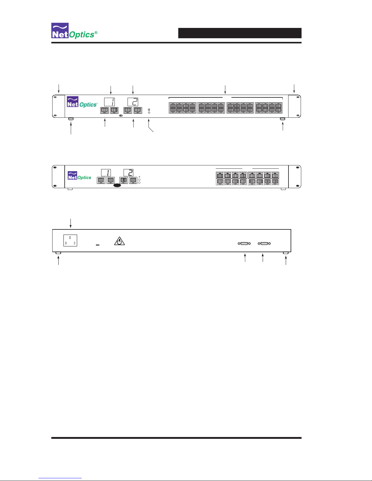
Product Diagrams
Figure 1: SW-CU-IL2X16 Front Panel
Figure 2: SW-CU-IL2X8 Front Panel
Figure 3: Rear Panel
Rubber Feet
(removable)
Mounting Brackets
(removable) Mounting Brackets
(removable)
Rubber Feet
(removable)
Analyzer Ports
10/100 RJ-45
Copper Ports
LED Display LED Display
Analyzer Ports
Power LED
(blue)
11 12
910 15 16
13 14
3 4
127 8
56
In-Line
A
B
12
A B A B
2x16 10/100 In-Line Switch
POWER
Rating 100 to 240 VAC
Input: 50-60Hz; 0.4A
+12VDC @10A
DB9 CONTROL
DB9 Control Interfaces
Power Plug
Rubber Feet
(removable)
Rubber Feet
(removable)
DB9 CONTROL
12345678
A
2
A
B
BA
1
B
In-Line Switch
In-Line
®
Monitor
1
2

2xN 10/100 In-Line SpyderSwitch
4
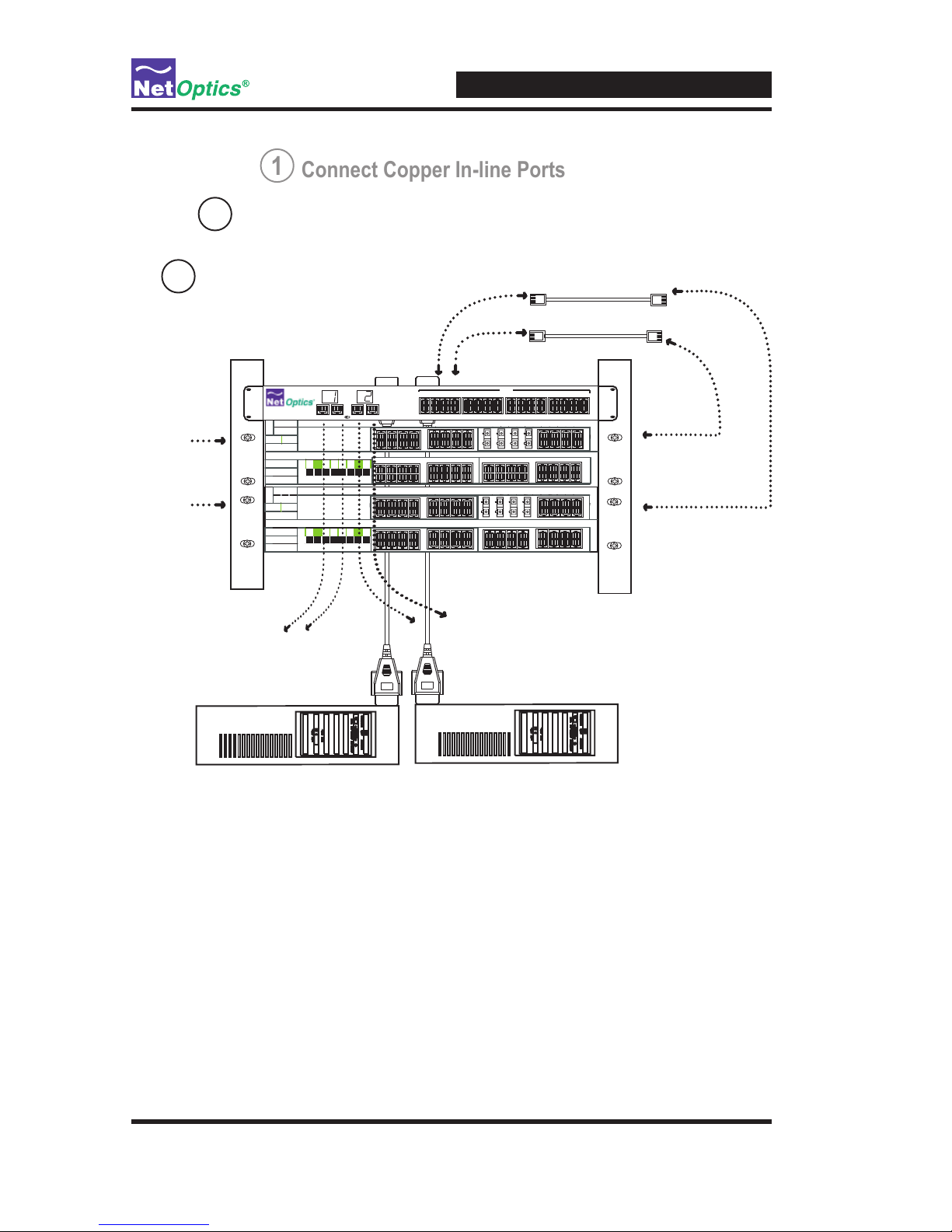
Connecting to the Network
1. Unpack the SpyderSwitch, verify that you have all components, and obtain
the required cables needed to successfully install the unit.
2. Connect Network 1 Port A to the appropriate network device using a CAT5
RJ45 cross-over cable.
3. Connect Network 1 Port B to the appropriate second network device using
a CAT5 RJ45 cross-over cable.
4. Verify that the Analyzer Switch Network 1 Ports are cabled in-line between
two devices.
5. Repeat Steps 2 thru 4 above for each additional network you want to Tap
and Monitor.
Figure 3: Connecting to the Network
Connect Copper In-line Ports
1
100Ba seTX/ 8F DDIFi berDA S
A B
OB
SY
A B
1x 2 x 3x 4x 5x 6 x 7x 8x
AC
1x 2x 3x 4x 5x 6 x 7x 8x 9x 10x 11x 1 2x 13x 14x 15 x1 6x 17x 1 8x 19x 20x 21 x 22x 23x 24x
10Ba seT
CIS MS
Æ
100Ba seTX/ 8F DDIFi berDA S
A B
OB
SY
B
1x 2 x 3x 4x 5x 6 x 7x 8x
AC
1x 2x 3x 4x 5x 6 x 7x 8x 9x 10x 11x 1 2x 13x 14x 15 x1 6x 17x 1 8x 19x 20x 21 x 22x 23x 24x
10Ba seT
CIS MS
Æ
Network
In-line
Ports
DCE
DTE
11 12
910 15 16
13 14
3 4
127 8
56
In-Line
A
B
12
A B A B
2x16 10/100 In-Line Switch
CAT5 RJ-45 Cable
CAT5 RJ-45 Cable

2xN 10/100 In-Line SpyderSwitch
5
Connecting to the Monitoring Devices
1. Supply power to the SpyderSwitch using the power supply included with
the unit. Verify that the Power LED illuminates.
2. Connect 2 CAT5 RJ45 straight-through cables to Analyzer Port 1 A/B on
the front of the SpyderSwitch.
3. Connect the other end of the RJ45 straight-through cables to the appropri-
ate ports on the monitoring device.
4. Connect one end of the supplied DB9 cable to the rst Serial porton the
rear of the SpyderSwitch.
5. Connect the other end of the DB9 cable to the Serial port of your
monitoring device.
6. Repeat Steps 2 thru 5 above to connect a second monitoring device to the
SpyderSwitch using Analyzer Port 2 and DB9 serial port 2.
Note: Until the software has been congured, the LED display will
read '00' meaning no port has been selected by the software.
Note: Straight-thru cable is used when connecting the SpyderSwitch to
a Router or NIC. Cross-over cable is used when connecting the
SpyderSwitch to a Network Switch or Hub.
2xN 10/100 In-Line SpyderSwitch
6
Figure 4: Connecting the Monitor Ports
Monitoring Device 1
DB9 cable connects
to monitoring device 1
CAT5 RJ45 straight-thru
cable connects to
monitoring device 1
T
H
I
C
K
N
E
T
T
H
I
N
N
E
T
U
T
P
R
E
M
O
T
E
S
W
1
C
O
N
S
O
L
E
A
T
M
D
C
E
A
T
M
D
T
E
Monitoring Device 2
T
H
I
C
K
N
E
T
T
H
I
N
N
E
T
U
T
P
R
E
M
O
T
E
S
W
1
C
O
N
S
O
L
E
A
T
M
D
C
E
A
T
M
D
T
E
CAT5 RJ45 straight-thru
cable connects to
monitoring device 2
DB9 cable connects
to monitoring device 2
Connect Copper In-line Ports
1
Connect Analyzer Ports
2
Connect DB9 Cable
3
DB9 cables connect to
rear of Analyzer Switch
DTE device
DCE device
100Ba seTX/ 8F DDIFi berDA S
A B
OB
SY
A B
1x 2 x 3x 4x 5x 6 x 7x 8x
AC
1x 2x 3x 4x 5x 6 x 7x 8x 9x 10x 11x 1 2x 13x 14x 15 x1 6x 17x 1 8x 19x 20x 21 x 22x 23x 24x
10Ba seT
CIS MS
Æ
100Ba seTX/ 8F DDIFi berDA S
A B
OB
SY
B
1x 2 x 3x 4x 5x 6 x 7x 8x
AC
1x 2x 3x 4x 5x 6 x 7x 8x 9x 10x 11x 1 2x 13x 14x 15 x1 6x 17x 1 8x 19x 20x 21 x 22x 23x 24x
10Ba seT
CIS MS
Æ
Network
In-line
Ports
DCE
DTE
11 12
910 15 16
13 14
3 4
127 8
56
In-Line
A
B
12
A B A B
2x16 10/100 In-Line Switch
CAT5 RJ-45 Cable
CAT5 RJ-45 Cable

2xN 10/100 In-Line SpyderSwitch
7
Installing PortRover Software
Included in your package is a CD containing the SpyderSwitch software. To
install the software, insert the CD into the device running your 10/100 ana-
lyzer software. As noted, this may be the actual monitoring device, or a PC.
The auto-installer will walk you through the installation steps.
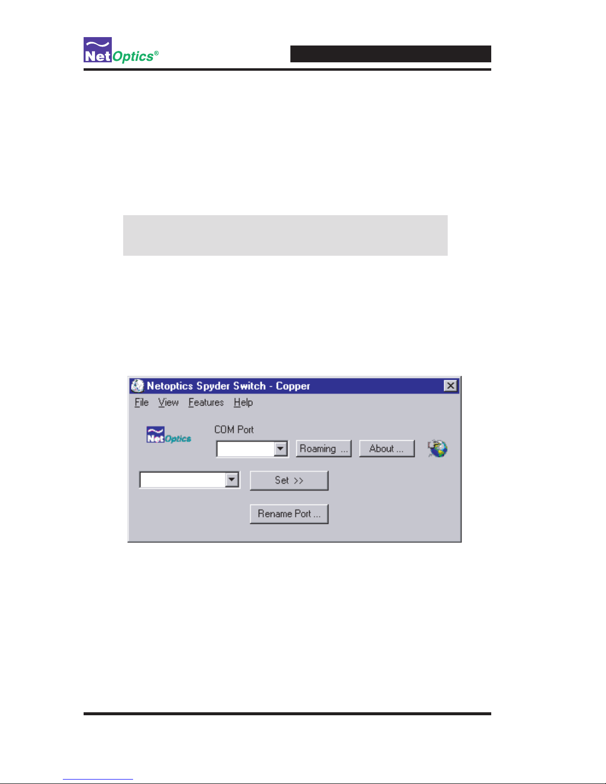
To begin using the Switch, double-click on the Switch software icon on your
desktop, or select the Switch software in your Programs menu. After the
splash screen, the interface below will appear on your screen.
Select the COM port on your monitoring device or PC that you wish to control
the SpyderSwitch through.
Repeat these steps to control the second 10/100 monitoring device.
Note: If your PC has two serial ports, you can control both the 10/100 inter-
faces from the same PC.
Note: If autorun is disabled, you will need to go to the drive with the
software CD and manually run Setup.exe to start the software installer.
Figure 5: PortRover Main Interface
2xN 10/100 In-Line SpyderSwitch
8
Using PortRover
With new PortRover software from Net Optics, you have multiple options to
control which network is being monitored!
If you would like to select monitoring ports one at a time, use the point-and-
click keypad that appears with the main interface.
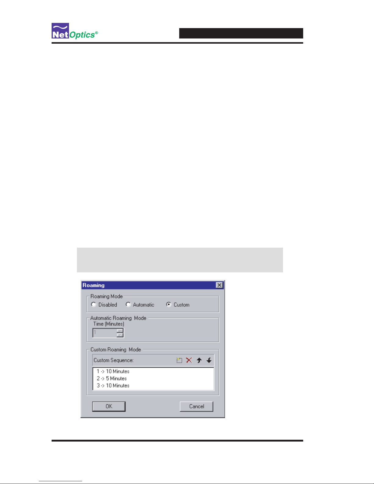
If you would like to take advantage of the roaming capabilities of the Port
Rover software, click on the Roaming button on the main interface. The inter-
face below will open on your screen.
Automatic Mode
Click on the Automatic radio button if you would like to program the
SpyderSwitch to scan across ports.
In the Automatic Roaming Mode box, type in the number of minutes that you
would like your monitoring device to spend on each port. For example, if you
type in '5', Port 1 will be monitored for 5 minutes, Port 2 will be monitored
for 5 minutes, and so on... Once each Port has been monitored, the cycle will
repeat.
Note: In Automatic Mode, the SpyderSwitch will monitor across all
its Ports, even if they are not connected to the network.
Figure 6: PortRover Roaming Interface

2xN 10/100 In-Line SpyderSwitch
9
Custom Mode
Click on the Custom radio button if you would like to program a custom
monitoring pattern for the SpyderSwitch to scan across ports.
To the upper right of the Custom Roaming Mode box click on the dotted
square icon. This will prompt you to enter a Span Port number, and the num-
ber of minutes you want to spend monitoring this port. This selection will be
entered into the Custom Sequence box.
Repeat this process for each selection you would like to add to the sequence.
To change the order of your selections, just highlight the selection and use the
up and down arrows to the upper right of the Custom Roaming Mode box.
To delete a selection, just highlight it and click on the xicon to the upper right
of the Custom Roaming Mode box.
Naming Ports
If you would like to name a port, go to the View Menu, and unselect Button
View. The Port Naming interface on the next page will appear.
To name a Port, click on the Rename Port button on the main interface. A
window will appear allowing you to name each Port connected to the Spy-
derSwitch. To select one of these ports to monitor, select a Port from the drop
down menu and click on the Set button. You can also go directly to the Roam-
ing mode by clicking on the Roaming button (the port names you have chosen
will be reected in the Roaming Interface).
You can return to the Main Interface by going back to the View Menu and
selecting Button View.
2xN 10/100 In-Line SpyderSwitch
10
Saving a Custom Monitoring Pattern
This is a very helpful feature if you like to alternate between patterns, or if
more than one person will be using the SpyderSwitch. To save your custom
monitoring pattern and port names, just go to the File menu, and select Save.
The pattern will be saved as a .txt le, which you can Open at any time
through the File menu.
Note: To use a saved monitoring pattern, you must have Roaming
enabled (and a COM port chosen).
Help Menu
If you have any questions, please call or email the team at Net Optics. You can
receive support for your SpyderSwitch by calling the phone number or email-
ing the address on the help menu. Our technical support team is available from
8 am to 5 pm pacic time, Monday through Friday.
Figure 7: Port Naming Interface
Port 1
COM 1

2xN 10/100 In-Line SpyderSwitch
11
Specications
Environment
Operating Temperature: 0ºC to 55ºC
Storage Temperature: -10ºC to 70ºC
Relative Humidity: 5% min, 95% max, non-condensing
Mechanical
Dimensions: 1.75"H x 12"D x 17"W
Power
Input: 100-240 VAC, 47-63 Hz
Cable Interface
Copper Cable Type: 22-24 AWG unshielded twisted pair cable, CAT5
Certications
Fully RoHS compliant
Connectors:
(4) RJ45, 8-pin connectors (monitor ports)
(2) DB9 serial control interfaces
(16) RJ45, 8-pin connectors (SW-CU-IL2X8 network ports)
(32) RJ45, 8-pin connectors (SW-CU-IL2X16 network ports)

2xN 10/100 In-Line SpyderSwitch
12
Limitation on Warranty and Liability
Net Optics offers a limited warranty for all its products. IN NO EVENT SHALL NET OPTICS, INC.
BE LIABLE FOR ANY DAMAGES INCURRED BY THE USE OF THE PRODUCTS (INCLUD-
ING BOTH HARDWARE AND SOFTWARE) DESCRIBED IN THIS MANUAL, OR BY ANY
DEFECT OR INACCURACY IN THIS MANUAL ITSELF. THIS INCLUDES BUT IS NOT LIM-
ITED TO LOST PROFITS, LOST SAVINGS, AND ANY INCIDENTAL OR CONSEQUENTIAL
DAMAGES ARISING FROM THE USE OR INABILITY TO USE THIS PRODUCT, even if Net
Optics has been advised of the possibility of such damages. Some states do not allow the exclusion
or limitation of implied warranties or liability for incidental or consequential damages, so the above
limitation or exclusion may not apply to you.
Net Optics, Inc. warrants this SpyderSwitch to be in good working order for a period of ONE YEAR
from the date of purchase from Net Optics or an authorized Net Optics reseller.
Should the unit fail anytime during the said ONE YEAR period, Net Optics will, at its discretion,
repair or replace the product. This warranty is limited to defects in workmanship and materials and
does not cover damage from accident, disaster, misuse, abuse or unauthorized modications.
If you have a problem and require service, please call the number at the end of this section and speak
with our technical service personnel. They may provide you with an RMA number, which must ac-
company any returned product. Return the product in its original shipping container (or equivalent)
insured and with proof of purchase.
Software Warranty Disclaimer
By using a Net Optics SpyderSwitch you agree to the terms and conditions of usage set forth by Net
Optics, Inc. on the installation CD. Please read this information before installing the software.
THE WARRANTY AND REMEDIES SET FORTH ABOVE ARE EXCLUSIVE AND IN LIEU OF
ALL OTHERS, EXPRESS OR IMPLIED. No Net Optics reseller, agent, or employee is authorized
to make any modication, extension, or addition to this warranty.
Net Optics is always open to any comments or suggestions you may have about its
products and/or this manual.
Send correspondence to
Net Optics, Inc.
5303 Betsy Ross Drive
Santa Clara, CA 95054 USA
Telephone: +1 (408) 737-7777
Fax: +1 (408) 745-7719
All Rights Reserved. Printed in the U.S.A. No part of this publication may be reproduced, transmit-
ted, transcribed, stored in a retrieval system, or translated into any language or computer language,
in any form, by any means, without prior written consent of Net Optics, Inc., with the following
exceptions: Any person is authorized to store documentation on a single computer for personal use
only and that the documentation contains Net Optics' copyright notice.

2xN 10/100 In-Line SpyderSwitch
13
Notes:

2xN 10/100 In-Line SpyderSwitch
14
Notes:


© 2007 by Net Optics, Inc. All Rights Reserved.
www.netoptics.com
Table of contents
Other Net Optics Network Router manuals

Popular Network Router manuals by other brands


Network Technologies
Network Technologies ETH-4X1 / 2X1 Installation and user guide

NetComm
NetComm N300 GATEWAY SERIES user guide

NETGEAR
NETGEAR SW502 installation guide

Teleste
Teleste EASI IP Series user manual

Edimax
Edimax GS-1008PHE Quick installation guide

Fritz!
Fritz! FRITZ!Box 6360 Cable quick guide


