Teleste EASI IP Series User manual

EASI™IP Series
User Manual
IPS User Manual, 59300144, rev002
IPS
Fast Ethernet Switch

IPS Series User Manual rev002
IPS Ethernet Switch Introduction................................................................................................................1
General ...................................................................................................................................................1
Switching Methods..................................................................................................................................1
Installation .....................................................................................................................................................2
Quick Instructions ...................................................................................................................................2
IPS Front Panel..............................................................................................................................................3
IPS Switch Mechanical Connections ......................................................................................................3
IPS Switch Models ..................................................................................................................................3
IPE Encoder / IPD Decoder with IPS Switch Mechanical Connections..................................................4
IPE Encoder / IPD Decoder with IPS Switch Models..............................................................................4
Connections ..................................................................................................................................................5
Local Port Connections...........................................................................................................................5
Up-Link Port Connections.......................................................................................................................5
Management Connection........................................................................................................................6
VLAN Connections..................................................................................................................................6
Fibre Connection.....................................................................................................................................6
Redundant Ring.............................................................................................................................................7
Introduction ............................................................................................................................................7
Ring Wiring .............................................................................................................................................7
Spanning Tree Protocol (STP) ...............................................................................................................8
Rapid Spanning Tree Protocol (RSTP) ...................................................................................................8
Fast Re-configuration of Network Topology (FRNTv0)...........................................................................8
Virtual LANs (VLAN).....................................................................................................................................9
General ...................................................................................................................................................9
Operation ...........................................................................................................................................9-10
IP Config Tool .............................................................................................................................................11
Introduction ...........................................................................................................................................11
System Requirements...........................................................................................................................11
How to Get the IP Config Tool...............................................................................................................11
How to Install the IP Config Tool ...........................................................................................................11
Operating ..............................................................................................................................................11
Device List Page..................................................................................................................................12
How to Configure the Switch.................................................................................................................12
Selected Device Page.........................................................................................................................13
Port Configuration Page.....................................................................................................................14
VLAN Configuration Page..................................................................................................................15
How to Configure VLAN...................................................................................................................15-16
How to Create the STP/RSTP Ring ......................................................................................................17
Creating FRNT v0 Ring.........................................................................................................................18
Notes on the IP Configuration Tool .......................................................................................................19
Trouble Shooting ...................................................................................................................................19
Firmware Upgrade via IP Config Tool ...................................................................................................19
IP Config Tool and Firmware Versions..................................................................................................19
Glossary.................................................................................................................................................20-22
Technical Specifications ........................................................................................................................... 23
Copyright Acknowledgements ..................................................................................................................25
Contents

Welcome, and thank you for purchasing Teleste’s EASI™ Products.
General
EASI™
IPS is a fully managed field hardened stand-alone Ethernet
Switch for video networking applications. The IPS is available as an
Ethernet Switch only device or alternatively as an integral part of
EASI™ IPE Encoder or IPD Decoder. The IPS supports SNMP
management, QoS (layer 2 and 3), network redundancy (FRNT 0
protocol), port configuration, port alarms, IGMP snooping and VLAN.
Switching Methods
The IPS stores incoming packets and then checks the packet for
check sum errors, if an error is found the packet is discarded. Other
reasons for discarding packets are undersized (less than 64 bytes) or
oversized packets (larger than 1522 bytes). Once the Switch verifies
the packets are correct they are then forwarded onto the port(s) of
the Switch and then to the corresponding network device. The
Switching decision is made based on the MAC tables (Layer 2
Switching). All MAC tables are created and maintained automatically.
When the IPS receives a packet on a port it stores the source MAC
address in the MAC table that corresponds to that port. If a node is
silent for a long time the MAC address will “age out” and be removed
from the table.
If the IPS does not have the MAC address in the table it will send the
packet to all ports (flooding). This is also the case for broadcast
packets and multicast packets. The MAC table can hold up to 8000
address entries.
The packet memory in the IPS is one megabyte, this is normally
enough to store thousands of packets (depending on size). The IPS
does not use flow control (IEEE 803.3x) to throttle end nodes to avoid
dropping packets during network congestion. Instead of flow control it
uses HOL (head of line blocking prevention). HOL guarantees that high
priority packets can be forwarded to ports congested by low priority
data. It is also possible to separate some ports for VLAN usage.
Stand-alone 8 port Fast Ethernet switch with 6
x
10/100Base-TX
local ports and 2
x
100Base-FX up-link ports, in-band management
IPS Fast Ethernet Switch Introduction
IPS Series User Manual rev002 1
Quick instructions
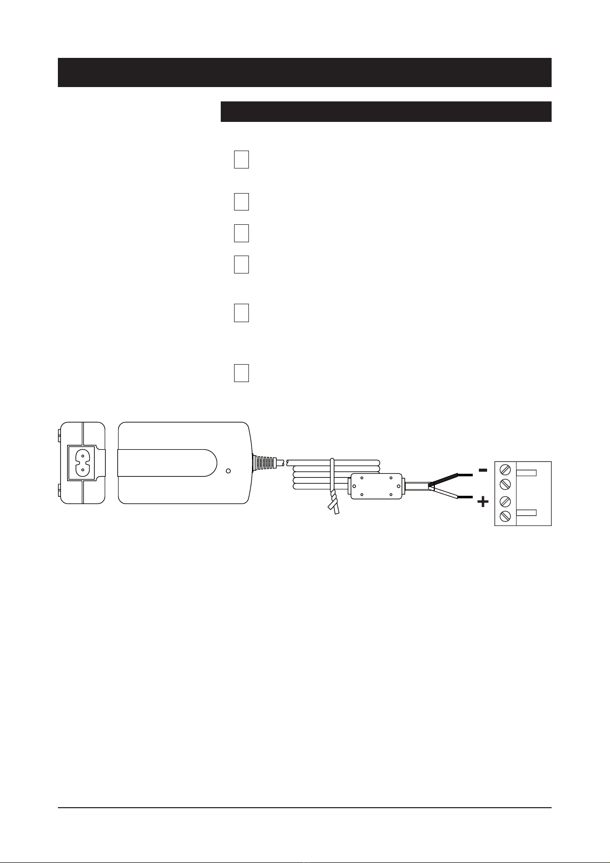
Install the field hardened IPS Ethernet Switch (1U high, 19”
wide) to the installation cabinet. A 12 V supply voltage is
provided by a CPS24x mains adapter.
Switch on the power and see that all indicator LEDs on the
front panel are going thru a routine checking cycle.
Connect all necessary 10/100Base-TX Ethernet cables.
Open IP Config tool on the computer connected to the
Switch and configure all necessary settings.
Make sure that the port indicator led on the front panel is lit
green on the ports where cables are connected. If the
indicator led is dark, the Ethernet connection does not
operate at that port.
Default network addresses for the devices are are
the following:
10.9.96.30 (IP)
255.255.255.0 (Netmask)
10.9.96.1 (Gateway)
Installation
1
3
4
5
6
2
Picture 1. CPS24x series power supply with connector.
2 IPS Series User Manual rev002
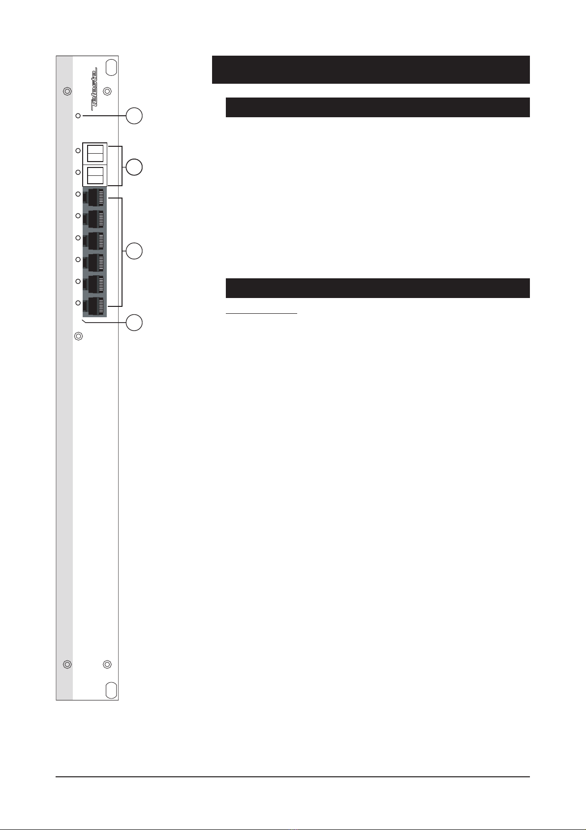
IPS Switch Mechanical Connections
1. Power led indicator.
2. 2 x Up-link ports, depending on model, dual MT-RJ (when optical
multimode) or dual-LC (when optical singlemode).
3. 6 x Local Ethernet 10/100Base-TX ports,
(RJ-45 female).
Note! Management connection to the device
can be created via any of local port.
4. Led indicators for local and up-link ports.
Models (stand-alone devices) / Up-link medias
IPS Switch only:
IPS3XX00XA CAT5 (100 m)
IPS3XX20XAMultimode (2 km)
IPS3XX30XA Singlemode Short Haul (15 km)
IPS3XX40XA Singlemode Medium Haul (40 km)
IPS Front Panel
Picture 2.
IPS3XX***A Ethernet
Switch / connections.
1
EASI
2
10/100Base-TX 100Base-FX
Tx Rx Tx Rx
3 4 5 6 7 8
Power
Ethernet Switch
1
2
3
4
IPS Series User Manual rev002 3
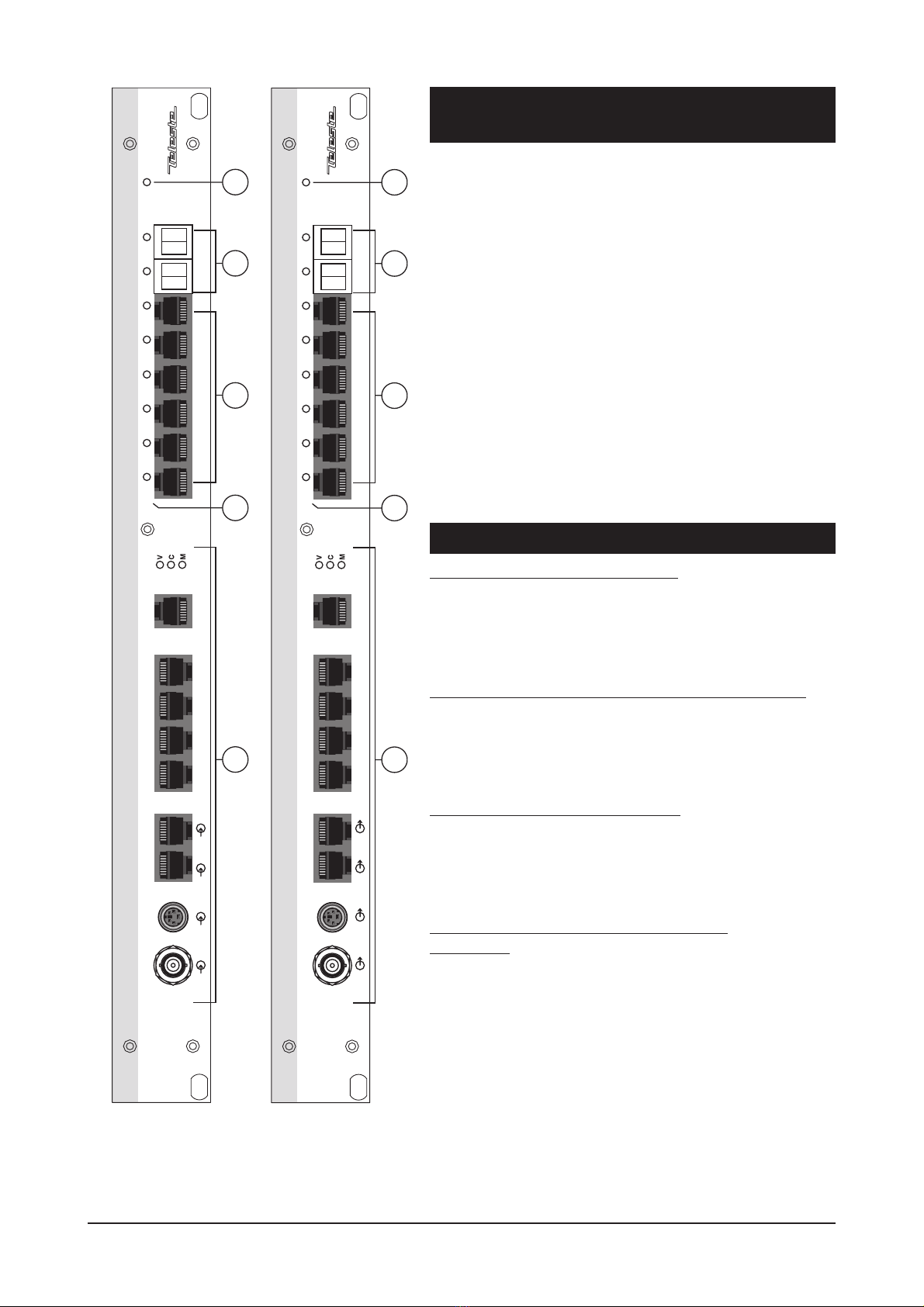
IPE Encoder & IPD Decoder with IPS Switch
Mechanical Connections
1. Power indicator led.
2.
2 x Up-link ports, depending on model, either
dual MT-RJ (when optical multimode) or
dual-LC (when optical singlemode).
3. 6 x Local Ethernet 10/100Base-TX ports,
(RJ-45 female).
Note! Management connection to the device
can be created via any of local port.
4. Led indicators for local and up-link ports.
5. IPE MPEG-2 Encoder / IPD MPEG-2
Decoder device.
Note! Refer to the IPE/IPD user manual for
detailed description.
Models (stand-alone devices) / Up-link medias
IPE MPEG-2 Encoder + IPS Switch:
IPE30000XA CAT5 (100 m)
IPE30020XA Multimode (2 km)
IPE30030XA Singlemode Short Haul (15 km)
IPE30040XA Singlemode Medium Haul (40 km)
IPE MPEG-2 Encoder + Terminal Server + IPS Switch:
IPE30100XA CAT5 (100 m)
IPE30120XA Multimode (2 km)
IPE30130XA Singlemode Short Haul (15 km)
IPE30140XA Singlemode Medium Haul (40 km)
IPD MPEG-2 Decoder + IPS Switch:
IPD30000XA CAT5 (100 m)
IPD30020XA Multimode (2 km)
IPD30030XA Singlemode Short Haul (15 km)
IPD30040XA Singlemode Medium Haul (40 km)
IPD MPEG-2 Decoder + Terminal Server +
IPS Switch:
IPD30100XA CAT5 (100 m)
IPD30120XA Multimode (2 km)
IPD30130XA Singlemode Short Haul (15 km)
IPD30140XA Singlemode Medium Haul (40 km)
Picture 3.
IPE3*****A MPEG-
2 Encoder /
connections.
Video 1S-Video Audio 1 Audio 2 Data 1 Data 2 Data 3 Mgmt
MPEG-2 Encoder Terminal Server
EASI
100Base-Tx
2
10/100Base-TX 100Base-FX
Tx Rx Tx Rx
3 4 5 6
Power
Ethernet Switch
7 8
1
2
3
4
5
Picture 4.
IPD3*****A MPEG-2
Decoder / connections.
Video 1S-Video Audio 1 Audio 2 Data 1 Data 2 Data 3 Mgmt
MPEG-2 Decoder Terminal Server Ethernet Switch
EASI
100Base-Tx
2
10/100Base-TX 100Base-FX
Tx Rx Tx Rx
3 4 5 6
Power
7 8
1
2
3
4
5
4 IPS Series User Manual rev002

Connections
Picture 5. 10/100Base-Tx Local and Up-link port connections.
Local Port Connections (6 pcs)
A standard IPS Switch comes with six (6) – 10/100Base-TX local
ports (CAT5). All local port connectors are type RJ-45 female (see
picture 5).
When a connection to local port is established the indicator led on
top of port is lit as solid green. This led also indicates the status of in/
outgoing data stream by blinking in sync with the data traffic. In a
case that the Ethernet signal is missing or the signal level is too low,
the indicator led is dark.
All local ports support extended 185 m distances when using high
quality CAT5 or better cables. Further all 10/100Base-TX UTP ports
support MDI/MDIX by automatically accepting both straight and
crossover Ethernet UTP cables. The Switch also automatically
corrects polarity errors. Furthermore the 10/100Base-TX UTP ports
have isolation barriers between the signal lines and
the internal electronics withstanding 1500 Vrms.
Up-Link Port Connections (2 pcs)
For Up-link network connections the Switch has two (2) 100Base-FX
Ethernet interfaces. The Ethernet 100Base connector in use is a dual
MT-RJ (when optical multimode) or dual-LC (when optical
singlemode). When Ethernet connection to the Up-link port is
established the indicator led on top of port is lit as solid green. This led
also indicates the status of in/outgoing data stream by blinking in sync
with the data traffic. In a case that the Ethernet signal is missing or the
signal level is too low, the indicator led is dark.
Pin 2 - Tx (-)
Pin 3 - Rx (+)
Pin 6 - Rx (-)
Pin 1 - Tx (+)
Pin 2 - Tx (-)
Pin 3 - Rx (+)
Pin 6 - Rx (-)
Pin 1 - Tx (+)
Pin 2 - Tx (-)
Pin 3 - Rx (+)
Pin 6 - Rx (-)
Pin 1 - Tx (+)
Pin 2 - Tx (-)
Pin 3 - Rx (+)
Pin 6 - Rx (-)
Pin 1 - Tx (+)
Pin 2 - Tx (-)
Pin 3 - Rx (+)
Pin 6 - Rx (-)
Pin 1 - Tx (+)
Pin 2 - Tx (-)
Pin 3 - Rx (+)
Pin 6 - Rx (-)
Pin 1 - Tx (+)
6 x 10/100Base-TX Full-Duplex
Local Ports
2 x 100Base-FX Full-Duplex
Up-link Ports
RX
TX
RX
TX
1 2 3 4 5 6 7 8
IPS Series User Manual rev002 5

Management Connection
The IPS Switch can be configured locally and/or remotely via any of the
Ethernet ports. However, port 1 is recommended for management
connection. The IPS switches are configured with IP Config Tool (see
page 11).
VLAN (up to 7 pcs)
A VLAN is a group of end stations with a common set of requirements,
independent of physical location. A VLAN has the same attributes as a
physical LAN but allows you to group end stations even if the VLANs
are not located physically on the same LAN segment. VLANs allow you
to group ports on a Switch to limit unicast, multicast, and broadcast
traffic flooding. Flooded traffic originating from a particular VLAN is only
flooded out other ports belonging to that VLAN.
Fibre Connection
The 1310 nm optical wavelenght is used for both multimode and
singlemode fibers. The optical mean launch powers are
as follows:
• Multimode fiber: -19...-14 dBm
• Single mode fiber (15km, short haul) : -15....-8 dBm
• Single mode fiber (40km, medium haul): -5...0 dBm
When installing the fiber optic cable, do not exceed the minimum
bending radius when connecting cable to the system.
Note! For correct optical operation ensure that all optical
connectors are cleaned immediately before mating. Connectors
should always be cleaned using high purity alcohol (e.g. methyl or
isopropyl alcohol). Dry the surfaces using clean compressed
air or other equivalent pressurized gas. The optical connectors on
the equipment should always be protected with dustcaps when
there is no fiber inserted.
Optical Ethernet connection meets Class 1 laser safety requirements
of IEC 825-2: 1993 and US department of health services 21 CFR
1040.10 and 1040.11 (1990) when operated within the specified
temperature, power supply and duty cycle ranges.
6 IPS Series User Manual rev002

Introduction
The redundant ring technology eliminates network failure caused by
fiber or copper failures. The EASITM IPS Switches supports standard
Spanning Tree Protocol (STP), Rapid Spanning Tree Protocol (RSTP)
and Fast Reconfiguration Network Topology (FRNT). The latter
protocol is alternative ring protocol optimized for rings containing many
Switches and requiring very low re-configuration times.
Two possible configurations for Switch redundancy are available. One
is Based on two Switches at each connection point in the ring, and the
other is Based on dual ring configuration. Redundant ring topology is
an excellent choice when high availability is required.
The re-configuration time is a critical factor for several applications.
Therefore Switches from the IPS series re-configure the network in
only 20 ms in case of ring failure (when using FRNT). Together with a
reliable hardware design and optional redundant power supplies
systems with maximum availability can be achieved. Switches are
configurated via Ethernet connection using PC with MS Windows
2000 operating system and IP Config Tool . This means that all
equipment can be installed prior to the configuration. The same IP
Config Tool can also be used for remote configuration and
management.
Note! No routers and other equipment filtering broadcast traffic can
be placed between the management PC and the ring Switches.
Ring Wiring
Connect port 8to port 7on the next Switch in the ring.
Note! RSTP/STP and FRNT can not be combined.
Redundant Ring
IPS Series User Manual rev002 7

Spanning Tree Protocol (STP)
The EASITM IPS switches support the Spanning Tree Protocol. The
Spanning Tree Protocol, which is also referred to as STP, is defined in
the IEEE Standard 802.1d.
The STP provides a loop-free network. When a switch supporting STP
recognizes a loop in the network topology, it blocks one or more
redundant ports. Spanning Tree Protocol continually explores the
network, so when the network topology changes, STP automatically
reconfigures switch ports to avoid the failure by blocking certain ports.
It allows the device to interact with other STP compliant devices in
your network to ensure that only one path exists between any two
stations on the network.
Rapid Spanning Tree Protocol (RSTP)
The EASITM IPS switches support the Rapid Spanning Tree Protocol.
The Rapid Spanning Tree Protocol, which is also referred to as
RSTP, is defined in the IEEE Standard 802.1w.
RSTP is an evolution of the STP, and provides faster spanning
tree convergence after a topology change. The 802.1d terminology
remains primarily the same, and most parameters have been left
unchanged so users familiar with 802.1d can rapidly configure the
new protocol comfortably.
Fast Re-configuration of Network Topology (FRNTv0)
The EASITM IPS switches support the Fast Re-configuration Topology
Protocol version 0, which is also referred to as FRNTv0. The FRNTv0
protocol is similar to the IEEE Spanning Tree Protocol (STP) except
for the following:
The FRNT keeps network load generated by ring packets at very low
level, thus the reaction times are faster. Each switch in a ring topology
has knowledge of the network topology, not only of its neighboring
switches as is the case for STP. A FRNT topology change event packet
will be sent directly to the focal point switch in case of a topology
change (e.g. a link loss or a link establishment), while a STP
implementation will only send STP control packets one network hop.
The ring is managed by one Switch selected as Focal Point in FRNT.
The other Switches in the ring are called member Switches. The
FRNT ring solution can recover from a failure in only 20 ms if such a
failure does occur.
Note: When using FRNT protocol all Switches have to be EASI™
IPS series Switches.
8 IPS Series User Manual rev002

General
A virtual LAN, commonly known as a vLAN or as a VLAN, is a
logically-independent network. Several VLANs can co-exist on a single
physical switch. A VLAN consists of a network of computers that
behave as if connected to the same wire - even though they may
actually physically connect to different segments of a LAN. Network
administrators configure VLANs through software rather than
hardware, which makes them extremely flexible. One of the biggest
advantages of VLANs emerges when physically moving a computer to
another location: it can stay on the same VLAN without the need for
any hardware reconfiguration. The IEEE 802.1Q tagging protocol
dominates the VLAN world.
A physical Ethernet network can be divided into several overlapping
Virtual LANs (VLAN) without having IEEE802.1Q tagging or GVRP
(Generic VLAN Registration Protocol) support on the Ethernet end
nodes. All Ethernet trunk ports are member of all of the seven legal
VLANs. A trunk port means a switch port connected to another switch;
where a network redundancy protocol is running (e.g. FRNT or RSTP).
This means that the VLAN tables on each switch are dynamically
updated during a network topology change. Thus, no VLAN user
configuration is required on the trunk ports.
See page 15 how to configure the VLAN settings.
Operation
The VLAN implementation is meant for both Ethernet end nodes that
support tagging and for those that do not. An Ethernet end node that
is not able to send tagged packets can, however, only participate in
one VLAN, i.e. the default VLAN id for the port is used as the VLAN
for such an end node. A default VLAN id for a given port will be
associated to each untagged packet received on the switch (or
tagged packet with VLAN id equal to 0). This VLAN id will be added
to packet as an IEEE802.1Q tag. This tag can be removed at the
output port(s) if the port(s) is configured for tag removal.
Seven different VLANs are available:
- White, VLAN id = 1, priority = 7 [high]
- Red, default VLAN id = 2, default priority = 0 [low]
- Blue, default VLAN id = 3, default priority = 0 [low]
- Green, default VLAN id = 4, default priority = 0 [low]
- Yellow, default VLAN id = 5, default priority = 0 [low]
- Brown, default VLAN id = 6, default priority = 0 [low]
- Pink, default VLAN id = 7, default priority = 0 [low]
Virtual LANs (VLAN)
IPS Series User Manual rev002 9

The VLAN that is selected as the default VLAN for a given port will
appear as an unchangeable VLAN, while other VLAN’s selected for
the same port has only relevance in case the end node connected to
the same port is able to send and receive packets with these VLAN
ids. All ports on a switch are members of the white VLAN, and this is
cannot be changed. However, an end node can not send “white”
packets unless the end node sends packets with the white VLAN id
unless the default VLAN for the port is the white VLAN.
Port 1 has the white VLAN id as the default VLAN is, and this cannot
be changed. An end node that is used for network management
(SNMP or IP configuration) must always use the white VLAN in order
to communicate with the switch’s CPU. Thus, the switch CPU can
always be accessed via port 1 with untagged packets, since port 1
has the white VLAN as the default VLAN.
Note! this means that red, blue, green, yellow, brown and pink
packets never will be sent to the switch CPU. This is important in
order to avoid that the port between the switch fabric and the CPU
becomes a bottleneck, where important packets might be lost (e.g.
FRNT control packets).
Example: A non white broadcast load close to full wire speed is not a
problem for correct switch CPU operation.
The tag is not removed on packets sent on a trunk port, and each
trunk port is member of all seven VLANs. This means that the user
does not need to set any VLAN parameters on the trunk ports, and
that any network topology change will be handled automatically.
The layer 2 priority of a given VLAN can also be set. I.e.:
- Priority 0, 1: QoS level 1
- Priority 2, 3: QoS level 2
- Priority 4, 5: QoS level 3
- Priority 6, 7: QoS level 4
This priority will be added to the tag. The legal VLAN id range is
1...4096. A few VLAN ids in this range are reserved for other use.
These ids can not be set in the IP Config Tool . The network should
only be based on switches enabled for VLAN or not. A mix of
switches with and without VLAN support will not provide the user with
the capability of tag removal on all parts of the network.
10 IPS Series User Manual rev002

IP Config Tool
Introduction
This chapter introduces how the IP Config Tool is used to configure
and manage the IPS switches. The IP Config Tool is used to
configure the network settings such as IP address, subnet mask and
default gateway of the IPS switches. This Tool is also used to
configure the redundant ring and time server parameters.
Port 1 is always advised to be used as a local management port.
In case a device is connected to the Port 1, only remote management
is available.
System Requirements
• The IPS Fast Ethernet switch (SW Ver 3.14 or newer)
• The X86 based PC computer running Windows 2000 or XP
• Ethernet network card
• Administrative rights are required during installation
• The IP Config Tool (TelesteIPConfig.exe, ver 9.6.1 or newer).
• The interconnection Ethernet cable
How to Get the IP Config Tool
You can download the latest version of IP Config Tool from Teleste’s
web site at: www.teleste.com.
How to Install the IP Config Tool
Unzip the file IP_Config_Tool.zip by using e.g. WinZip and extract
all the files to the folder you want. Ensure that all files reside in the
same folder and that you can find the folder after you extract them
there. Start the program by running TelesteIPConfigxxx.exe.
Operating
The IP Config Tool consists principally of several windows. On the
Selected Device page you can configure the chosen device.
The IP Config Tool has the following configuration display pages that
are introduced in this document:
- IP Configuration / Device list
- Selected Device
- Port configuration
- VLAN configuration
The information on configuration sheets is shown in data fields or
boxes. You can change settings in data fields or boxes whose
background is white. Place your cursor in the desired data field or
box and enter the new setting. Some settings are entered by ticking a
checkbox or clicking on a radio button, by selecting from a pull-down
list or by scrolling digits with the help of spin buttons.
Information without datafield or box is read only parameter and can
not be change.
IPS Series User Manual rev002 11

Picture 6. Device list page view (with one Switch).
How to Configure the Switch
1. Connect the PC into the Ethernet port 1 of the IPS Switch via
Ethernet cable and open the IP Config Tool by running the
TelesteIPConfig.exe program.
The following “IP configuration” window appears on the screen
(like picture 6).
2. Assign a free IP address, which is in the same subnet as the PC, to
the “Default IP” and click button until the Switch(es)
appears on the device list. Now all Switches in the same network will
appear on the device list (e.g. one switch in picture 6).
3. Click on the Switch that you want to configure --> “Selected
Device” window will appear on the screen (picture 7). From this
window you can modify the switch settings.
Device List Page
12 IPS Series User Manual rev002

Picture 7. Selected Device configuration page view.
Click on the Switch in the IP Configuration page window’s device list.
“Selected Device” configuration page will appear on the screen (picture 7).
On this page you can see/modify the switch’s configuration, as following:
IP address: Device IP address
Subnet mask: Mask for subnet definition
MAC address: Device MAC address
Host name: User definable alias name for the device
Location: User definable location name for the device
IP gateway address: Gateway address for router definition
Enable SNMP: Enables Switch to use SNMP
Enable DHCP client: Enables Switch to use DHCP protocol to obtaine an
IP address. When used with Teleste Libretto product the selection also
enables download of config from remote (root Switch)
Enable FRNT v0 ring: Enables FRNT v0 for redundancy Switching
Enable RSTP/STP ring: Enables RSTP/STP for redundancy Switching
Network focal point: The device can be set as focal point in FRNT or
RSTP/STP ring (root Switch)
RSTP trunk ports:
Enables RSTP signalling on the selected trunk port(s)
Enable port alarm: Enables port alarm for selected port(s)
Port config: Opens port configuration window
Define IGMP trunk ports: Specifies the switch trunk ports. IGMP
information is forwarded on the port towards the IGMP Querier and on
the switch trunk ports
Enable IGMP: Enables IGMP (RFC 1112)
Multicast stop filter: Enables filtering of all multicast traffic which does
not have registered receiver (unknown multicasts)
Auto mode: Ensures that only one Querier is present in the existing
network. A device with the lowest IP address will be the Querier
Querier: Enables Switch to act as a Querier (IGMP server)
Query interval (sec): Configurable IGMP query interval in seconds
Enable VLAN: Enables VLAN function
VLAN button: Opens VLAN configuration window
not in use
press the “Get” button to view the
device’s current settings.
press first the “Set” button and
then the “Restart” button to
activate the settings.
Reboots the device
Selected Device Page
IPS Series User Manual rev002 13
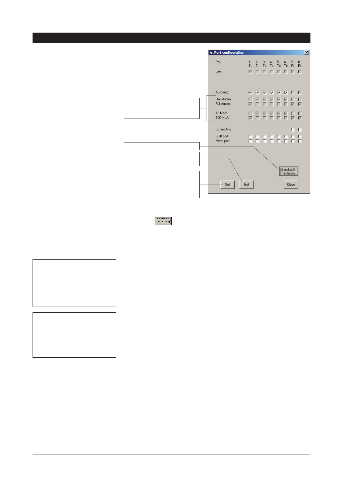
Picture 8. Selected Device configuration page view.
Click on the Switch button in the selected device window.
“Port configuration” window will appear on the screen (picture 8). On this
page you can see/modify the port configuration, as following:
Link: Shows whether the link is up or not and link type, either Tx
(electrical) or Fx (optical)
Auto-neg:
Enables the auto-negotiation feature, which allows the switch
to discover and manage the speed and duplex mode settings on a given
port. The combination that provides the best performance will be
automatically selected
Half duplex & Full duplex: Sets the duplex mode on a given port. If Auto-
neg feature is enabled on a given port, this setting can not be modified
10/100 Mb/s: Sets the speed on a given port. If Auto-neg feature is
enabled on a given port, this setting can not be modified
Sniff port & Mirror port:
This feature allows to sniff the traffic on a given
port. The “Sniffed port” should be selected and all the traffic will be
redirected to the selected “Mirror port”
Scrambling: Allows the switch to code the traffic flowing through the
selected port. This setting is only available for the trunk ports and must be
the same on both sides of the link. This parameter is important for
backward compatibility: In older firmware versions scrambling is always
enabled (and cannot be changed)
press the “Get” button to view
the device’s current settings.
Press the ‘Set’ button after any
changes. Any changes will
have immediate effect (switch
restart is not required).
Port Configuration Page
These settings will be selected
automatically when Auto-neg
is enabled.
not in use
14 IPS Series User Manual rev002
These settings are user-editable if
the auto-neg tick box for the port is
not ticked.
Note! The auto-negotiation,
duplex connectivity and speed
settings for an Fx port are not
user-editable.
The fiber configuration is not
compatible with older firmware
releases of the switch). The latest
versions can handle both
scrambled and non scrambled fiber
communication. This feature is
configurable via IPConfig or SNMP.

Picture 9. VLAN configuration page default view.
How to Configure VLAN
The VLAN tick box must be ticked in order to enable the VLAN button.
Click on the VLAN in the Selected Device window.
“VLAN configuration” page will appear on the screen (picture 9). On this
page you can see/modify the switch´s configuration regarding VLANs.
The following VLAN parameters can be set:
• Default VLAN per port
White, Red, Blue, Green, Yellow, Brown and Pink. The default VLAN
for a given port is the only VLAN available for the port if the end node
connected to the port is unable to send and receive tagged packets.
Selection is done by pushing up/down buttons on the upper side.
Default VLAN for port 1 is fixed to White.
• Additional VLANs per port
A given port can be member of additional VLANs. This feature is only
relevant is the end node is able to send and receive tagged packets
with these VLANs´ ids. All ports are as well members of the White
VLAN and can´t be changed.
• VLAN id’s (The legal range is 1..4095). The default are the following:
o White VLAN id = 1
o Red VLAN id = 2
o Blue VLAN id = 3
o Green VLAN id = 4
o Yellow VLAN id = 5
o Brown VLAN id = 6
o Pink VLAN id = 7
NOTE! VLANs are defined by their VLAN id. The color scale is
intented just as a help. When configuring VLANs in different switches,
only VLANs with the same id will be part of the same logical group.
Therefore, the same VLAN color in all switches must have the same id
in order to succeed.
Press the “Get” button to
view the device’s current
VLAN settings.
VLAN Configuration Page
Press the “Set” button to
set the device’s changed
VLAN settings. To activate
the settings, the switch
must be restart.
IPS Series User Manual rev002 15

Picture 10. VLAN configuration page example view.
• Priority
It is the Layer 2 Priority for each VLAN. The legal range is 0...7. The
lower the value is, the lower the priority for the given VLAN. For
VLAN White priority is fixed to 7.
• Remove tag
Tag removal on egress. If this option is ticked, VLAN tags will be
removed from Ethernet packets on egress: output data will have no
VLAN tag. This option is always ticked in port 1 and can´t be changed.
Trunk ports must be member of all VLANs and the VLAN tags must not
be removed. This settings allow data from all VLANs to be transmitted
transparently through the network between different switches.
See picture 10 for a setup example on VLAN configuration:
• Ports 1, 2, 7 and 8 have as default VLAN “White”. VLAN id is 1 and
its priority is 7.
• Ports 3 and 4 have as default VLAN “Red”. VLAN id is 2 and its
priority is 0.
• Ports 5 and 6 have as default VLAN “Blue”. VLAN id is 3 and its
priority is 0.
• VLAN tags are removed on egress on all local ports (ports 1 to 6)
• Trunk ports (7 and 8) are members of all VLANs and VLAN tags are
not removed on egress.
After configurating VLANs, save the settings by pressing “Set” button
and then end VLAN configuration session by pressing “Clo button. To
activate the settings restart the Switch at the Device Configuration Page
by pressing Rest button.
It´s recommended that tag
removal operation is activated
(tickbox is checked) due to the
fact that not all NICs (Network
Intrface Card) are able to
understand VLAN tagged frames.
Trunk ports are automatically
detected, when at least two
switches are connected together.
VLAN settings for these ports are
automatically set and then can
not be changed.
16 IPS Series User Manual rev002

How to Create the STP/RSTP Ring
1. Select which Switch will be your Root/Focal Point Switch to
manage the ring.
2. Connect your PC with IP Config Tool installed to the Root/Focal
Point Switch port 1.
3. Open Teleste IP Config Tool and assign a free IP address, which is
in the same subnet as the PC, to the “Default IP” and click
for button until the Switch(es) appears on the device list.
Now all Switches in the same network will appear on the device list.
4. Click on the Switch which is chosen to be Root/Focal Point
Switch and tick “Network focal point” box.
5. Restart the Switch by clicking button.
6. Set IP address and subnet mask (no restart required).
7. Connect the rest of the Switches (or one at a time) and set IP
address and subnet mask.
Note! In case that more than one switch have been selected to be
Root/Focal Point, the one which has smallest IP address will act as
network’s Root/Focal Point.
8. Close the ring and click “Scan for button to check the status of
all Switches.
IPS Series User Manual rev002 17

Creating FRNT v0 Ring
In a FRNT v0 ring configure only one IPS switch must be configured
to be the network Focal Point. The Focal Point switch have the role
as Redundancy Manager, and thus be responsible for recovery when
a connection between the switches is broken. To set up a FRNT v0
configuration the following steps must be followed:
1. Connect the switches in a bus topology (do not close the ring
before the switches are all configured for FRNT 0)
2. Define the Switch, that shall be the network Focal Point
3. Power up the switch and connect this to the network
4. Assign an IP address for the configuration software (ensure the
address range is within the same Subnet as your assigned IP
address for your PC)
5. Press the “Scan for devices” button. The Switches on the network
will be listed
6. Click on the focal point switch from list
7. A new configuration Window will open
8. If required; assign a new IP address and Subnet address for this
Switch
9. Press the “Set” button to assign this IP address and Subnet
settings to the Switch
10. Tick the “Enable FRNT Ring” and “Network focal point” to set the
Switch to be the Focal Point and Bus Member to ensure the
Switch configured to run within a Redundant Ring
11. Press the “Set” button (all your changes performed will be set)
12. Press the “Rest button to re-configure the Switch. The Switch
will run through the start sequence. During this period
communication to the Switch will be lost
13. Connect the next Switch into the ring
14. Press the “Scan for d button. The second Switch will appear on
the list
15. Click on the second Switch from list
16. If required; assign a new IP address and Subnet address for this
Switch
17. Tick “Enable FRNT ring” to ensure the Switch is configured to run
within a Redundant Ring
18. Press the “Set” button.
19. Press the “Rest button to re-configure the Switch. The Switch
will run through the start sequence. During this period
communication to the Switch will be lost.
20. Continue connecting Switches in this manner until the ring has
been completed
21. Close the ring
FRNT version 0, configuration rules are as follows:
• Port 7 and 8 are FRNT version 0 ports
• Always connect port 8 to 7, 8 to 7, .. 8 to 7 through the ring
(never 7 to 7 or 8 to 8)
• One switch as the network focal point (root)
18 IPS Series User Manual rev002
Other manuals for EASI IP Series
1
Table of contents
Other Teleste Network Router manuals


