NET Corsight CO1041C2 Quick start guide

Operational Manual
Smart Vision System - Matrix | Line Scan
Operational Manual - re v . 2.0._10_2016
IMPORTANT INFORMATION
This operational manual applies to the following models:
CO1041C2/M2 | CO4136C2/M2/IR2 | CO4206C2/M2 | CO1503C2/M2
COL6270M2 | COL6435M2
Please note that all data and illustrations are subject to error, change and omissionswithout notice. CORSIGH T

2/50
Please note that all data and illustrations are subject to error, change and omissionswithout notice. CORSIGH T
Operational Manual - rev. 2.0_10_2016
Table of Contents
Operational Manual ......................................................................................................................................1
Smart Vision System - Matrix | Line Scan......................................................................................................1
Ta b l e o f C o n t e n t s ...........................................................................................................................................2
Overview .......................................................................................................................................................5
Scope of Delivery...........................................................................................................................................6
C o n te n t ......................................................................................................................................................6
Options ......................................................................................................................................................6
Option Lighting ........................................................................................................................ 6
Option Tube Extension............................................................................................................. 6
Option Operating System ........................................................................................................ 6
Cable Accessories .................................................................................................................... 6
L e g a l N o t i c e ...................................................................................................................................................7
Regulatory notices .....................................................................................................................................7
R o H S ..........................................................................................................................................................7
Safety Precau tio ns .........................................................................................................................................8
General Handing .......................................................................................................................................9
Usage Notes ................................................................................................................................................11
Handle carefully..................................................................................................................... 11
Environmental operating conditions ..................................................................................... 11
Check a combination with the lens ....................................................................................... 11
Do not shoot under intense light ........................................................................................... 11
Dropping Frames ................................................................................................................... 11
Occurrence of moiré .............................................................................................................. 12
Occurrence of noise on the screen ........................................................................................ 12
Handling of the protective cap .............................................................................................. 12
If the equipment is not to be used for a long duration ......................................................... 12
Maintenance ......................................................................................................................... 12

3/50
Please note that all data and illustrations are subject to error, change and omissionswithout notice. CORSIGH T
Operational Manual - rev. 2.0_10_2016
Following information is only for EU-member states:........................................................... 13
System Requirements..................................................................................................................................14
Standard conformity................................................................................................................................14
GenICam ................................................................................................................................ 14
Environmental requirements ...................................................................................................................14
Quick start ...................................................................................................................................................15
Prepare the camera.................................................................................................................................15
Testing the camera ..................................................................................................................................15
Basic camera features .............................................................................................................................17
System architecture.....................................................................................................................................21
Overview..................................................................................................................................................21
Dimensions ..............................................................................................................................................22
Mounting points ......................................................................................................................................22
Housing....................................................................................................................................................23
Lens mount, optical head ........................................................................................................................23
Integrated strobe ring .............................................................................................................................23
Sensor ......................................................................................................................................................23
Sensor types .......................................................................................................................... 23
IR-cut or AR filter .....................................................................................................................................24
Changing or removing the filter ............................................................................................ 25
Cover glass............................................................................................................................. 25
Input and output signals .........................................................................................................................25
DC power input ...................................................................................................................... 26
PC interfaces.......................................................................................................................... 26
Trigger input .......................................................................................................................... 27
Optocoupler interface............................................................................................................ 27
Serial port interface ............................................................................................................... 32
Connector and cable description .............................................................................................................33
I/O connector......................................................................................................................... 33
PC system connector.............................................................................................................. 34
Ethernet connector ................................................................................................................ 36

4/50
Please note that all data and illustrations are subject to error, change and omissionswithout notice. CORSIGH T
Operational Manual - rev. 2.0_10_2016
Status LED................................................................................................................................................37
Appendix A. Technical specifications for individual ....................................................................................38
Mo dels .........................................................................................................................................................38
CORSI GHT CO 1041 C2 ..............................................................................................................................39
CORSI GHT CO104 1M2 .............................................................................................................................40
CORSI GHT CO 4136 C2 ..............................................................................................................................41
CORSI GHT CO 4136M2 .............................................................................................................................42
CORSI GHT CO413 6IR 2 .............................................................................................................................43
CORSI GHT CO 4206 C2 ..............................................................................................................................44
CORSI GHT CO420 6M2 .............................................................................................................................45
CORSI GHT CO 1503 C2 ..............................................................................................................................46
CORSI GHT CO150 3M2 .............................................................................................................................47
CORSI GHT CO L6270M2 /COL6435M2 .....................................................................................................48
Technical Support ........................................................................................................................................49
Websites ................................................................................................................................ 49
Email ...................................................................................................................................... 49
Phone..................................................................................................................................... 49
Fax ......................................................................................................................................... 49
I m p r i n t .........................................................................................................................................................50

5/50
Please note that all data and illustrations are subject to error, change and omissionswithout notice. CORSIGH T
Operational Manual - rev. 2.0_10_2016
Overview
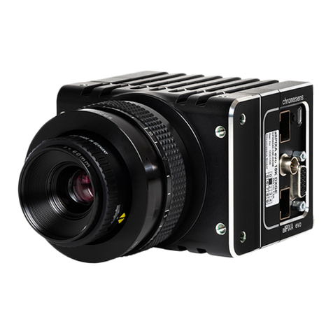
CORSIGHT is a vision system with embedded computer providing maximum flexibility in industrial
applications for decentralized image processing. CORSIGHT runs under Windows or Linux and with any
common image processing software. Its solid housing, interfaces and connectors are in accordance to
industrial standards.
product name
C O R S I G H T
PC technology
Embedded PC with Intel Atom E3845 1.91GHz
4 GB DDR3/1333MHz (up to 8 GB on request)
16 GB built-i n S A T A -SSD flash disk (up to 32 GB on request)
µSD card slot
Gigabit Ethernet interface, USB 2.0 interface, DP++ output
2× WLAN/Bluetoth antenna connector, LUT for image manipulation
MPEG-4/H264 encoder/decoder
sensors
CMOS, monochrome/NIR & Bayer encoded color,
progressive scanning, various trigger modes
sensor specific information
R e f e r t o Appendix A, Technical specifications for individual models
image acquisition & t r a n s f e r
DMA to the C O R S I G H T host memory
lens mount
C-mount (CS-mount on request)
dimensions
65×109×73 mm (W×H×D, without connectors)
weight
516 g
power input
24 ±10% VDC, 15 W (typical), 25 W (max.) or PoE+
digital I/O
4×opto in, 4×opto out, TTL in, TTL out, RS232 interface
supported operating systems
DMA
Microsoft Windows Embedded Standard 7 (WES7), Linux
Directly supported image processing libraries Adaptive Vision Studio, Halcon,
ActivVisionTools, Common Vision Blox, MATLAB, OpenCV
order information
contact our sales team > http://net-gmbh.com/

6/50
Please note that all data and illustrations are subject to error, change and omissionswithout notice. CORSIGH T
Operational Manual - rev. 2.0_10_2016
Scope of Delivery
Content
-CORSIGHT housing camera
-CD-ROM with SynView (SDK) for Microsoft Windows Embedded Standard 7 and Linux
compatible to GenICam, GenTL and GigE Vision standards including
SynView Explorer to control CO RSIGH T c a m e r a s
A comprehensive programming library with automatic source code generator
SynView GigE Vision Configuration Tool
Firmware maintenance tool
Software drivers for CORSIG HT an d all rel ated ha rdware s o f t w a r e d o c u m e n t a tion
Free of charge software updates are listed in the download area o n N E T ´ s w e b s it e .
Options
A n y CORS IG HT bas ic mo de l (se e Appendix A, Technical specifications for individual models) can be
further customized. Ple a se contact NET for more information about NET´s current offering and pricing.
Option Lighting
-CORSIG HT Flash light module, IR (order no. 01007200xx)
-CORSIG HT Flash light module, cool white, 6500K (order no. 01007300xx)
Option Tube Extension
-CORSIG HT Tube, length 50.5mm ( o r de r n o . 60015001xx)
Option Operating System
-Windows Embedded Standard 7 License
Cable Accessories
-CORSIG HT LAN cable, RJ45, 5m (orde r no . 06093900xx)
-CORSIG HT Cam era Ca ble for DP++, USB, RS232 (order no. 06100400xx)
-CORSIG HT Camera Cable for I/O, Power supply, 3m (order no. 06095000xx)

7/50
Please note that all data and illustrations are subject to error, change and omissionswithout notice. CORSIGH T
Operational Manual - rev. 2.0_10_2016
Legal Notice
Regulatory notices
The cameras should be used with properly shielded cables (and other equipment) as recommended
in this manual.
Please contact us if you need further information regarding the necessary equipment.
RoHS
The product fulfills the requirements of the EU directive RoHS 2011/65/EU in the currently valid version
from 8.June 2011 regarding the restrictive use of certain hazardous materials in electric applications
within the allowable limits.

8/50
Please note that all data and illustrations are subject to error, change and omissionswithout notice. CORSIGH T
Operational Manual - rev. 2.0_10_2016
Safety Precautions
Before using this product, read these safety precautions carefully. Important information is shown in this
Operational Manual to protect users from injuries and property damages, and to enable them to use the
product safely and correctly. Please be sure to thoroughly understand the meanings of the following
signs and symbols before reading the main text that follows, and observe the instructions given herein.
[Definition of Safety Signs]
Notes
*1:“Serious injury” refers to cases of loss of eyesight, wounds, burns (high or low temperature), electric
shock, broken bones, poisoning, etc., which leave after-effects or which requires hospitalization or a long
period of outpatient treatment of cure.
*2:"Light to moderate injuries" refers to injuries, burns, electric shock etc. that d o n o t re q u i r e
hospitalization or long-term tre atme nt.
*3:"Property damage" refers to cases of extensive damage involving damage to buildings, equipment,
farm animals, pet animals and other belongings.
[Explanation of Safety Symbols]
Safety Signs
De sc r ipt io n
WARNING
Indicates a potentially hazardous situation that may result in death or
serious injury (*1) in the event of improper handling.
C A U T I O N
Indicates a potentially hazardous situation that may result in light to
moderate injuries (*2) or only in property damage (*3) in the event of
improper handling.
Safety Symbols
Des cr ipt io n
PROHIBITED
This sign indicates PROHIBITION (Do not).
The content of prohibition is shown by a picture or words beside the symbol.
M A N D A T O R Y
This sign indicates MANDATORY ACTION (You are required to do).
The content of action is shown by a picture or words beside the symbol.

9/50
Please note that all data and illustrations are subject to error, change and omissionswithout notice. CORSIGH T
Operational Manual - rev. 2.0_10_2016
General Handing
WARNING
Stop operation immediately when any abnormality or defect occurs.
If abnormal conditions are present, such as smoke, a burning smell, ingress of water or
foreign matter, or if the equipment is dropped or malfunctions, fire or electric shock
may result. Be always sure to disconnect the power cable from the wall socket at once
and contact your dealer.
Unplug
Do not disassemble, repair, or modify the equipment. Otherwise, fire or electric shock
may result. For internal repair, inspection, or cleaning, contact your sales
representative.
Never pull
apart
Do not place anything on the equipment.
If metallic objects, liquid, or other foreign matter enters the equipment, fire or electric
shock may result.
A v o i d
Do not install the equipment in an unstable or inclined location or locations subject to
vibration or impact. Otherwise, the equipment may topple over and cause personal
injury.
A v o i d
During an electrical storm, do not touch the power cable and the connection cable.
Otherwise, an electric shock may result.
Do not to u c h
Instruction
Use the specified voltage.Use of an unspecified voltage may result in fire or electric
shock.
Do not handle roughly, damaged, fabricated, bent forcefully, pulled, twisted, bundled,
placed under heavy objects or heated the power cable and the connection cable.
Otherwise, fire or electric shock may result.
A v o i d

10/50
Please note that all data and illustrations are subject to error, change and omissionswithout notice. CORSIGH T
Operational Manual - rev. 2.0_10_2016
C A U T I O N
Observe the following when installing the equipment:
Do not cover the equipment with a cloth, etc.
Do not place the equipment in a narrow location where heat is likely to accumulate.
Otherwise, heat will accumulate inside the equipment, possibly resulting in a fire.
Instruction
Use only specified the power cable and the connection cables. Otherwise, f i r e o r
electric shock may result.
Instruction
Do not give strong impact against the equipment. It may cause the trouble.
A v o i d
When performing connection, turn off power. When connecting the power cable and
the connection cable, turn off the equipment power. Otherwise, fire or electric shock
m a y r e s u l t .
Instruction
Do not expose the camera head to any intensive light (such as direct sunlight).
Otherwise, its inner image pickup device might get damaged.
A v o i d
Avoid short-circuiting signal output. Otherwise, a malfunction may occur.
A v o i d
Avoid giving a strong shock against the camera body. It might cause a breakdown or
damage. If your camera is used in a system where its camera connector is subjected to
strong repetitive shocks, its camera connector is possible to break down. If you intend
to use your camera in such a situation, if possible, bundle and fix a camera cable in the
place near the camera, and do not transmit a shock to the camera connector.
A v o i d

11/50
Please note that all data and illustrations are subject to error, change and omissionswithout notice. CORSIGH T
Operational Manual - rev. 2.0_10_2016
Usage Notes
Handle carefully
Do not drop the equipment or allow it to be subject to strong impact or vibration, as such action may
cause malfunctions. Further, do not damage the connection cable, since this may cause wire breakage.
Environmental operating conditions
Do not use the product in locations where the ambient temperature or humidity exceeds the
specifications. Otherwise, image quality may be degraded or internal components may be adversely
affected. In particular, do not use the product in areas exposed to direct sunlight. Moreover, during
shooting under high temperatures, vertical stripes or white spots (noise) may be produced, depending
on the subject or camera conditions (such as increased gain). However, such phenomena are not
malfunctions.
Check a combination with the lens
Depending on the lens and lighting you use, an image is reflected as a ghost in the imaging area.
However, this is not because of a fault of the camera. In addition, depending on the lens you use, the
performance of the camera may not be brought out fully due to deterioration in resolution and
brightness in the peripheral area, aberration and others. Be sure to check a combination with the
camera by using the lens and lightning you actually use. When installing a lens in the camera, make
sure carefully that it is not tilted. In addition, use a mounting screw free from defects and dirt.
Otherwise, the camera may be unable to be removed. Install a next lens; its dimension of protrusion
from b o t t o m o f t h e s c r e w is equal to or less than 10 mm. If a lens does not stand to this condition, it
might not be installed to this camera.
Do not shoot under intense light
Avoid intense light such as spot lights on part of the screen because it may cause blooming or smears. If
intense light falls on the screen, vertical stripes may appear on the screen, but this is not a malfunction.
Dropping Frames
Depends on your PC or Gigabit Ethernet interface board configurations, images may not be captured
properly (e.g. dropping frames). In this case, change to frame rate setting lower.

12/50
Please note that all data and illustrations are subject to error, change and omissionswithout notice. CORSIGH T
Operational Manual - rev. 2.0_10_2016
Do not expose the camera's image-pickup-plane to sunlight or other intense light directly. I t s i n n e r i m a g e
sensor m i g h t b e d a m a g e d .
Occurrence of moiré
If you shoot thin stripe patterns, moiré patterns (interference fringes) may appear. This is not a
malfunction.
Occurrence of noise on the screen
If an intense magnetic or electromagnetic field is generated near the camera or connection cable, noise
may be generated on the screen. If this occurs, move the camera or the cable.
Handling of the protective cap
If the camera is not in use, attach the lens cap to the camera to protect the image pickup surface.
If the equipment is not to be used for a long duration
Turn off power to the camera for safety.
Maintenance
Turn off power to the equipment and wipe it with a dry cloth. If it becomes severely contaminated,
gently wipe the affected areas with a soft cloth dampened with diluted neutral detergent. Never use
alcohol, benzene, thinner, or other chemicals because such chemicals may damage or discolor the paint
and indications. If the image pickup surface becomes dusty, contaminated, or scratched, consult your
sales representative.

13/50
Please note that all data and illustrations are subject to error, change and omissionswithout notice. CORSIGH T
Operational Manual - rev. 2.0_10_2016
Following information is only for EU-member states:
The use of the symbol indicates that this product may not be treated as
household waste. By ensuring this product is disposed correctly, you help
to prevent potential negative consequences for the environment and
human health, which could otherwise be caused by inappropriate waste
handling of this product. For more detailed information about the take-
back and recycling of this product, please contact your supplier where you
purchased the product.
Do not throw batteries and rechargeable batteries into the household
waste!
Customers are legally obliged to return used and rechargeable batteries,
whether t h e y c o ntain harmful substances or not, designated disposal sites
or collecting sites in shops selling batteries. By doing so you are
contributing to a better and cleaner environment.

14/50
Please note that all data and illustrations are subject to error, change and omissionswithout notice. CORSIGH T
Operational Manual - rev. 2.0_10_2016
System Requirements
Standard conformity
GenICam
The cameras (and supporting libraries) fully implement the GenICam standard, including SFNC
(Standard Features Naming Convention) and GenTL. Thanks to the full GenTL compatibility, the
cameras are plug & play compatible with all GenTL capable libraries, such as Adaptive Vision Studio,
Halcon, Common
Vision Blox or MATLAB. CORSIGHT supports the operating systems Microsoft Windows
Embedded Standard 7 and Linux.
Environmental requirements
-
operati ng tem perature: 0 °C - 50 °C
-operating relative humidity: 20% - 95%, non-condensin g
-allow sufficient air circulation around the camera to prevent heat-up
-ingress protection rating: IP67
If exposed to environmental conditions outside the specified limits, the camera performance can be
significantly degraded or the camera can be damaged.

15/50
Please note that all data and illustrations are subject to error, change and omissionswithout notice. CORSIGH T
Operational Manual - rev. 2.0_10_2016
Quick start
This chapter is intended to help users wanting to start quickly with basic usage of the cameras, without
studying the entire documentation. The information in this chapter duplicates information in the
following parts of the manual. Whenever in doubt, please refer to the corresponding chapters of the
manual, providing detailed description of given problems.
Prepare the camera
-Unpack the camera, connect all the necessary peripheral. If needed, check the interface
connectors description in S e c t i o n , “Connector and cable description” .
-P o w e r up the camera using proper 24V power supply.
-Assuming that the desired operating system is already pre-installed on the camera, no additional
steps are needed and the camera is rea d y f o r S y n V i e w installation and test. Otherwise, install the
operating system, following instructions of the operating system supplier. Install the
necessarydevice drivers available from our download area.
Testing the camera
The S y n V i e w package contains the S y n V i e w Explorer tool, which allows to enumerate, connect and
confi gure ca mera, acq uire images or generate sample source code for S y n V i e w API. It is a useful tool for
testing both the S y n V i e w and camera functionality.
Start the tool from system menu: Start −> P r o g r a m s −> S y n V i e w -> S y n V i e w Explorer (under
Linux, run /opt/synview/bin/sv . e x p l o r e r ) .
Connect the camera to be tested — select it in the list of found cameras and press the Connect
c a m e r a button.

16/50
Please note that all data and illustrations are subject to error, change and omissionswithout notice. CORSIGH T
Operational Manual - rev. 2.0_10_2016
Configure the camera features as desired. Pay attention especially to features in Image F o r m a t
Control and Acquisition Control categories.
When prepared, click the Start acquisition button — the camera should start acquiring. If not,
verify again, if the camera was not set to triggered mode, while no trigger was attached.
While the acquisition is active, you can still adjust the runtime parameters, such as exposure
time or gain. Basic acquisition parameters, such as pixel format or trigger mode become l o c k e d
when the acquisition starts.
-
When finished, click the Stop acquisition button and exit.

17/50
Please note that all data and illustrations are subject to error, change and omissionswithout notice. CORSIGH T
Operational Manual - rev. 2.0_10_2016
Basic camera features
This section s h o w s the most essential camera features r e l e v a nt for the basic tests.
The S y n V i e w Explorer displays by default only the “basic” camera features intended to handle the
most common tasks. To display also the more advanced features, you need to switch to the “expert ”
feature level. Note that the third available level, “guru”, is intended just for debugging and should
not be used for normal operation.
Image format. The basic properties of the acquired image can be configured through features in the Image
Format category:
Pixel format
The Pixel Format feature is an enumeration allowing to specify the type of image data delivered to the
application buffer. The available pixel formats differ among camera models. In general, they can be
-Monochrome, with various number of bits per pixel, eg. Mono 8 or Mono 12.
-Bayer encoded, with sensor-dependent Bayer formats, eg. Bayer GR 8 or Bayer BG 8. In this case
the application needs to decode the Bayer encodedimage buffer to get a proper color ima g e —
S y nView API provides functions for this.
-
RGB color format, providing true RGB output, in this case the Bayer decoding is performed directly
by the camera.
I m a g e s i z e
The camera will acquire full size image by default. The acquired image size c a n b e reduced using the
Width and Height features, which set the acquired image size in pixels. The field of view will be
automatically centered within the full sensor image.

18/50
Please note that all data and illustrations are subject to error, change and omissionswithout notice. CORSIGH T
Operational Manual - rev. 2.0_10_2016
Acquisition parameters. The luminance of the acquired image can be controlled either explicitly through
exposure time and gain functions, or automatically through corresponding auto-functions.
Exposure time
The Exposure Time f e a t u r e i n Acquisition Control category configures the length of the exposure in
microseconds.
Analog gain
Analog gain to be applied on the sensor during acquired image digitization can be configured through
corresponding features in Analog Control category. Verify that the Gain Selector feature is set to Analog
(some cameras models support also digital gain). Now the Gain feature controls the desired analog gain
value in decibel.
Auto-functions
Selected camera models support automatic gain and/or automatic exposure functions, when the camera
keeps adjusting given parameter automatically, to maintain constant image luminance. The features will
be displayed in the feature tree only if the camera supports them. To switch the auto function on,
navigate to corresponding control feature, Automatic Exposure in Acquisition Control category or
Automatic Gain in Analog Control category and switch them from Off to Continuous.
Triggered acquisition. The camera starts by default in “free running” mode — acquiring continuous stream of
image frames. On the other hand in the triggered mode, the acquisition of individual frames can be explicitly

19/50
Please note that all data and illustrations are subject to error, change and omissionswithout notice. CORSIGH T
Operational Manual - rev. 2.0_10_2016
controlled by hardware or software triggers. The trigger related features are located in the Acquisition Control
category.
Triggered mode
To switch the camera to triggered mode, open the Trigger Selector subtree and set Trigger Mode to On.
After starting the acquisition again, the camera will acquire images only when explicit trigger signal
arrives.
Trigger source
The Trigger Source enumeration allows to select where should the camera “listen for triggers. You can
select either S o f t w a r e or one of the camera's I/O lines. The assignment of the I/O lines to the conn e c t o r
pins is described in S e c t i o n, “Connector and cable description” .
Software triggering
The software triggers can be issued during active acquisition in triggered mode, regardless whether the
trigger source is set to Software or a physical I/O line. To apply the software trigger, select the Generate
Software Trigger feature and click the button in the tool bar.
S t r o b e
The strobe can be configured using features in the Digital I/O Control category, after switching the
feature visibility level to “expert”. Select the desired output line, where the strobe pulses should be
applied through Line Selector (the I/O line mapping to interface connector pins is described in Section,
“Connector and cable description” ). Switch the strobe on for the selected line by setting Line Source to
Exposure Active. The camera will issue a strobe pulse aligned with the exposure for every acquired
f r a m e . T h e s t r o b e output is available only in triggered mode. In case the camera has an integrated
Strobe Ring, its Strobe can be controlled through the Strobe Control category. Select which Clusters to
use with Strobe Enable. Strobe Duration sets the length of the Strobe Pulse.

20/50
Please note that all data and illustrations are subject to error, change and omissionswithout notice. CORSIGH T
Operational Manual - rev. 2.0_10_2016
Information about the camera. It is frequently necessary to query the basic information about the camera. The
information is available through features in the Device Control category.
Device identity
The most important features identifying the camera are Vendor Name and Model Name. The camera's
serial number is stored as string in feature Device ID (available only in “expert” feature level). Finally, the
“nick-name” used to identify the device is accessible (read/write) in DeviceUser ID.
Firmware version
The version of the firmware loaded on the camera is accessible as string in feature Device Firmware
V e r s i o n .
This manual suits for next models
10
Table of contents
