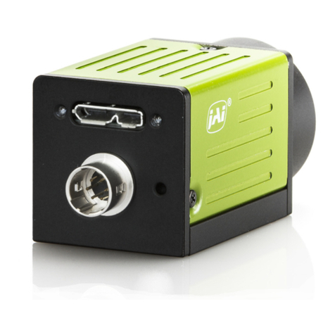
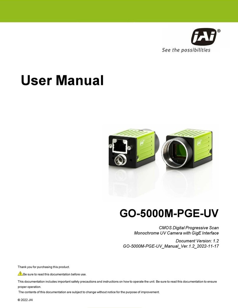
JAI GO-5000M-PMCL-UV User manual

Thank you for purchasing this product.
Be sure to read this documentation before use.
This documentation includes important safety precautions and instructions on how to operate the unit. Be sure to read this documentation to ensure
proper operation.
The contents of this documentation are subject to change without notice for the purpose of improvement.
© 2022 JAI
User Manual
GO-5000M-PMCL-UV
CMOS Digital Progressive Scan
Monochrome UV Camera with Mini Camera Link Interface
Document Version: 1.1
GO-5000M-PMCL-UV_Manual_Ver.1.1_2022-11-17

GO-5000M-PMCL-UV User Manual (Ver. 1.1) Table of Contents
- 2 -
Table of Contents
Table of Contents 2
About Technical Note 5
Notice/Warranty 6
Notice 6
Warranty 6
Certifications 6
CE Compliance 6
FCC 6
Warning 7
Supplement 8
Usage Precautions 9
Notes on Cable Configurations 9
Notes on Attaching the Lens 9
Notes on Camera Link Cable Connections 9
Phenomena Specific to CMOS Image Sensors 10
Notes on Exportation 10
Features 11
Feature Overview 11
Parts Identification 13
①Lens Mount (C-Mount) 13
②POWER/TRIG LED 14
③ ④ Camera Link Connector 1 and 2 14
⑤Camera Locking Screw Holes (M3, 3mm depth) 15
Preparation 16
Short ASCII Commands 16
Step 1: Connect Devices 17
①Lens 18
②Direct Mounting (or Use MP-43 Tripod AdapterPlate) 18
③Camera Link Cable 19
④Frame Grabber Board 19

GO-5000M-PMCL-UV User Manual (Ver. 1.1) Table of Contents
- 3 -
Step 2: Verify Camera Operation 19
Step 3: Verify the Connection Between the Camera and PC 20
Step 4: Change the Camera Settings 21
Configure the Output Format 21
Step 5: Adjust the Image Quality 22
Display the Image 22
Adjust the Gain 22
Adjust the Black Level 23
Step 6: Save the Settings 23
Save the User Settings 24
Load the User Settings 24
Main Functions 25
Camera Link Interface 25
Digital IN/OUT Interface 29
Pulse Generator 33
Sensor Layout 37
Camera Output Format (Tap Geometry) 38
Output Timing (Horizontal) 42
1x8-1Y (LVAL Active/Non-Active, HTotal) 43
1x4-1Y (LVAL Active/Non-Active, HTotal) 44
1x3-1Y (LVAL Active/Non-Active, HTotal) 45
1x2-1Y (LVAL Active/Non-Active, HTotal) 46
1x8-1Y (1 LineClock, Horizontal Frequency/Period) 47
1x4-1Y (1 LineClock, Horizontal Frequency/Period) 51
1x3-1Y (1 LineClock, Horizontal Frequency/Period) 54
1x2-1Y (1 LineClock, Horizontal Frequency/Period) 55
Output Timing (Vertical) 58
1x8-1Y (FVAL, DVAL, V-Offset, Exposure Time) 59
1x4-1Y (FVAL, DVAL, V-Offset, Exposure Time) 60
1x3-1Y (FVAL, DVAL, V-Offset, Exposure Time) 61
1x2-1Y (FVAL, DVAL, V-Offset, Exposure Time) 62
1x8-1Y (Frame Period, Exposure Time, Exposure End to FVAL Active Start) 63
GO-5000M-PMCL-UV User Manual (Ver. 1.1) Table of Contents
- 4 -
1x4-1Y (Frame Period, Exposure Time, Exposure End to FVAL Active Start) 64
1x3-1Y (Frame Period, Exposure Time, Exposure End to FVAL Active Start) 65
1x2-1Y (Frame Period, Exposure Time, Exposure End to FVAL Active Start) 66
ROI (Region of Interest) Settings 67
Digital Output Bit Allocation 67
Acquisition Control 68
Exposure Settings 70
Trigger Control 73
Normal Continuous Operation 75
Timed Mode 76
Trigger Width Mode 77
RCT Mode 78
RCT Mode Together with ALC Function 79
Sequence Mode 80
Trigger Sequence Mode Timing 81
Sequence Index Table (Default) 81
Descriptions of Index Table Parameters 82
Multi ROIFunction 83
Operation and Function Matrix 85
Black Level Control 86
Gain Control 87
LUT (Lookup Table) 89
Gamma 90
Shading Correction 91
Blemish Compensation 91
ALC (Automatic Level Control) 92
HDR (High Dynamic Range) 93
Miscellaneous 94
External Appearance and Dimensions 94
Spectral Response 95
Specifications 96
Appendix 100

GO-5000M-PMCL-UV User Manual (Ver. 1.1) Table of Contents
- 5 -
Short ASCII Command Communication Protocol 102
Protocol (Short ASCII Command) 102
GenCP Bootstrap Register 103
Technology Specific Bootstrap Register 104
Device Control 104
Image Format Control 105
Acquisition Control 106
Analog Control 107
Digital IO Control 108
LUT Control 109
Transport Layer Control 109
User Set Control 109
JAI Custom 110
User's Record 121
Revision History 122
About Technical Note
Some additional technical information is provided on the JAI website as Technical Notes. In this
manual, if a technical note is available for a particular topic, the above icon is shown. Please refer to
the following URL for Technical notes.
https://www.jai.com/support-software/technical-notes

GO-5000M-PMCL-UV User Manual (Ver. 1.1) Notice/Warranty
- 6 -
Notice/Warranty
Notice
The material contained in this manual consists of information that is proprietary to JAI Ltd., Japan, and
may only be used by the purchasers of the product. JAI Ltd., Japan makes no warranty for the use of
its product and assumes no responsibility for any errors which may appear or for damages resulting
from the use of the information contained herein. JAI Ltd., Japan reserves the right to make changes
without notice.
Company and product names mentioned in this manual are trademarks or registered trademarks of
their respective owners.
Warranty
For information about the warranty, please contact your factory representative.
Certifications
CE Compliance
As defined by the Directive 2004/108/EC of the European Parliament and of the Council, EMC
(Electromagnetic compatibility), JAI Ltd., Japan declares that GO-5000M-PMCL-UV complies with the
following provisions applying to their standards.
EN 61000-6-3 (Generic emission standard part 1)
EN 61000-6-2 (Generic immunity standard part 1)
FCC
This equipment has been tested and found to comply with the limits for a Class A digital device,
pursuant to Part 15 of the FCC Rules. These limits are designed to provide reasonable protection
against harmful interference in a residential installation. This equipment generates, uses and can
radiate radio frequency energy and, if not installed and used in accordance with the instructions, may
cause harmful interference to radio communications. However, there is no guarantee that interference
will not occur in a particular installation. If this equipment does cause harmful interference to radio or
television reception, which can be determined by turning the equipment off and on, the user is
encouraged to try to correct the interference by one or more of the following measures:
lReorient or relocate the receiving antenna.
lIncrease the separation between the equipment and receiver.
lConnect the equipment into an outlet on a circuit different from that to which the receiver is

GO-5000M-PMCL-UV User Manual (Ver. 1.1) Notice/Warranty
- 7 -
connected.
lConsult the dealer or an experienced radio/TV technician for help.
Warning
Changes or modifications to this unit not expressly approved by the party responsible for FCC
compliance could void the user’s authority to operate the equipment.

GO-5000M-PMCL-UV User Manual (Ver. 1.1) Notice/Warranty
- 8 -
Supplement
The following statement is related to the regulation on “Measures for the Administration of the Control
of Pollution by Electronic Information Products “, known as “China RoHS“. The table shows contained
Hazardous Substances in this camera.
mark shows that the environment-friendly use period of contained Hazardous Substances is 15
years.
重 要 注 意 事 项
有毒,有害物质或元素名称及含量表
根据中华人民共和国信息产业部『电子信息产品污染控制管理办法』, 本产品《 有毒,有害物质或
元素名称及含量表》如下.
部件名称
有毒有害物质或元素
铅
(Pb)
汞
(Hg)
镉
(Cd)
六价铬
(Cr (VI))
多溴联苯
(PBB)
多溴二苯醚
(PBDE)
电路板 × 〇 〇 〇 〇 〇
螺丝 × 〇 〇 〇 〇 〇
插座 × 〇 〇 〇 〇 〇
..... ..... ..... ..... ..... ..... .....
〇:表示该有毒有害物质在该部件所有均质材料中的含量均在GB/T 26572-2011规定的限量要求以下。
×:表示该有毒有害物质至少在该部件的某一均质材料中的含量超出GB/T 26572-2011规定的限量要求。
环保使用期限
电子信息产品中含有的有毒有害物质或元素在正常使用的条件下不会发生外 泄或突变、
电子信息产品用户使用该电子信息产品不会对环境造成严重污染 或对其人身、财产造成
严重损害的期限。
数字「15」为期限15年。

GO-5000M-PMCL-UV User Manual (Ver. 1.1) Usage Precautions
- 9 -
Usage Precautions
Notes on Cable Configurations
The presence of lighting equipment and television receivers nearby may result in video noise. In such
cases, change the cable configurations or placement.
Notes on Attaching the Lens
How to Clean a Sensor
Avoiding Dust Particles
When attaching the lens to the camera, stray dust and other particles may adhere to the sensor
surface and rear surface of the lens. Be careful of the following when attaching the lens.
lWork in a clean environment.
lDo not remove the caps from the camera and lens until immediately before you attach the lens.
lTo prevent dust from adhering to surfaces, point the camera and lens downward and do not
allow the lens surface to come into contact with your hands or other objects.
lAlways use a blower brush to remove any dust that adheres.
lNever use your hands or cloth, blow with your mouth, or use other methods to remove dust.
Notes on Camera Link Cable Connections
Secure the locking screws on the connector manually, and do
not use a driver. Do not secure the screws too tightly. Doing so
may wear down the screw threads on the camera. (Tightening
torque: 0.15 N·m or less)
Caution: Secure manually. Do not secure too tightly.

GO-5000M-PMCL-UV User Manual (Ver. 1.1) Usage Precautions
- 10 -
Phenomena Specific to CMOS Image Sensors
The following phenomena are known to occur on cameras equipped with CMOS image sensors.
These do not indicate malfunctions.
lAliasing: When shooting straight lines, stripes, and similar patterns, vertical aliasing (zigzag
distortion) may appear on the monitor.
lBlooming: When strong light enters the camera, some pixels on the CMOS image sensor may
receive much more light than they are designed to hold, causing the accumulated signal charge
to overflow into surrounding pixels. This “blooming” phenomenon can be seen in the image but
does not affect the operation of the camera.
lFixed pattern noise: When shooting dark objects in high-temperature conditions, fixed pattern
noise may occur throughout the entire video monitor screen.
lDefective pixels: Defective pixels (white and black pixels) of the CMOS image sensor are
minimized at the factory according to shipping standards. However, as this phenomenon can be
affected by the ambient temperature, camera settings (e.g., high sensitivity and long exposure),
and other factors, be sure to operate within the camera’s specified operating environment.
Notes on Exportation
When exporting this product, please follow the export regulations of your country or region.

GO-5000M-PMCL-UV User Manual (Ver. 1.1) Features
- 11 -
Features
This camera is an industrial progressive scan camera equipped with a Type 1 global shutter CMOS
image sensor with 5.2 effective megapixels (2560 × 2048). This CMOS image sensor has sensitivity in
the UV region. The unit is compact and lightweight in design and is equipped with Mini Camera Link
interface supporting a “Power over Camera Link” capability.
Compact and lightweight
The unit’s compact size (approx. 29mm × 29mm × 41.5mm, excluding lens mount) and lightweight
design (approx. 46 g) allows for easy assembly and installation.
Feature Overview
lNew small-in-size Type 1 CMOS 5-megapixel progressive scan camera
lUtilizes two Mini Camera Link interfaces to support Base, Medium or Full configurations
lAspect ratio 5:4, 2560 (H) x 2048 (V) - 5 million effective pixels
l5 μm square pixels
lS/N 55dB (Dark compression is used, traditional measurement method)
l8-bit, 10-bit or 12-bit output
l107.2 frames/second with full resolution in continuous operation for 8-tap, 63.6 frames/second
for 4-tap, 47.8 frames/second for 3-tap, and 31.9 fps for 2-tap readout
lSupports ROI (Region Of Interest) modes for faster frame rate
l0dB to +24dB gain control
l10 μs (1/100,000) to 8 seconds exposure control in 1 μs step
lAuto exposure control
lTimed and trigger width exposure control
lRCT trigger mode for specific applications
lALC control with combined function of AGC and Auto Shutter
lVarious pre-processing circuits are provided
lProgrammable LUT
lGamma correction (3 steps: 0.45, 0.6 and 1.0)
lShading correction

GO-5000M-PMCL-UV User Manual (Ver. 1.1) Features
- 12 -
lBlemish compensation
lHDR (High Dynamic Range) function
lC-mount for lens mount
lAccepts power over Mini Camera Link

GO-5000M-PMCL-UV User Manual (Ver. 1.1) Parts Identification
- 13 -
Parts Identification
①Lens Mount (C-Mount) ②POWER/TRIG LED
③ ④ Camera Link Connector 1 and 2 ⑤Camera Locking Screw Holes (M3, 3mm depth)
①Lens Mount (C-Mount)
Mount a C-mount lens, microscope adapter, etc. here.
Note: Before mounting a lens, be sure to refer to ①Lens and confirm the precautions for
attaching a lens and the supported lens types.

GO-5000M-PMCL-UV User Manual (Ver. 1.1) Parts Identification
- 14 -
②POWER/TRIG LED
Indicates the power or trigger input status.
LED Status
Lit amber Camera initializing
Lit green Camera in operation
Blinking
green
During operation in trigger mode, trigger signals are being input.
Note: The blinking interval is not related to the actual input interval of the external
trigger.
③ ④ Camera Link Connector 1 and 2
Connect a cable that is compatible with Mini Camera Link (SDR) connectors here.
Camera Link Connector 1
Pin Input
Output Signal Description
1, 26 Power Power
2 (-), 15 (+) Out X_OUT0 Data out
3 (-), 16 (+) Out X_OUT1 Data out
4 (-), 17 (+) Out X_OUT2 Data out
5 (-), 18 (+) Out X_Clk CL Clock
6 (-), 19 (+) Out X_OUT3 Data output
7 (+), 20 (-) In SerTC (RxD) LVDS Serial Control
8 (-), 21 (+) Out SerTFG (TxD)
9 (-), 22 (+) In CC1 (Trigger) JAIstandard trigger
10 (+), 23 (-) In CC2 (Reserved)
11, 24 N.C
12, 25 N.C
13, 14 Shield GND

GO-5000M-PMCL-UV User Manual (Ver. 1.1) Parts Identification
- 15 -
Note: Pins 7 & 20 are N.C.
Camera Link Connector 2
Pin Input
Output Signal Description
1, 26 Power Power
2 (-), 15 (+) Out Y_OUT0 Data out
3 (-), 16 (+) Out Y_OUT1 Data out
4 (-), 17 (+) Out Y_OUT2 Data out
5 (-), 18 (+) Out Y_Clk CL Clock
6 (-), 19 (+) Out Y_OUT3 Data out
8 (-), 21 (+) Out Z_OUT0 Data out
9 (-), 22 (+) Out Z_OUT1 Data out
10 (-), 23 (+) Out Z_OUT2 Data out
11 (-), 24 (+) Out Z_Clk CL Clock
12 (+), 25 (-) Out Z_OUT3 Data out
13, 14 Shield GND
⑤Camera Locking Screw Holes (M3, 3mm depth)
Use these holes when attaching an MP-43 tripod adapter plate (optional) or mounting the camera
directly to a wall or other structural system.

GO-5000M-PMCL-UV User Manual (Ver. 1.1) Preparation
- 16 -
Preparation
Read this section to learn how the camera connects to devices and accessories. The preparation
process is described below.
Step 1: Connect Devices
lConnect the lens, Camera Link cable, AC adapter, computer, and other devices.
Step 2: Verify Camera Operation
lVerify whether the camera is turned on and ready for use.
Step 3: Verify the Connection Between the Camera and PC
lVerify whether the camera is properly recognized via Control Tool.
Configure the Output Format
lRefer to the procedure for changing the output format setting as an example and change
various settings as necessary.
Step 5: Adjust the Image Quality
lRefer to the procedures for adjusting the gain and black level as examples and adjust the
image quality.
Step 6: Save the Settings
lSave the current setting configurations in user memory.
Short ASCII Commands
The most universal method for controlling a Camera Link camera such as the GO-5000M-PMCL-UV is
by the use of short ASCII commands sent via serial communications. All Camera Link frame grabber
boards support the use of these short ASCII commands. SDKs that utilize these ASCII commands for
developing machine vision applications are typically available from the grabber manufacturer, as well
as from third-party vendors.
This section describes how to configure various camera settings using serial communication and
specific short ASCII commands. A complete list of all available ASCII commands for this camera can
be found at the end of this manual.

GO-5000M-PMCL-UV User Manual (Ver. 1.1) Preparation
- 17 -
Later sections of the manual refer to GenICam nomenclature for various features/functions and
includes a complete list of all camera settings starting. The GO-5000M-PMCL-UV fully supports
applications written using GenICam-based SDKs. The advantage of this is that programs written using
GenICam names can be applied with little or no modification to control cameras with other GenICam-
compliant interfaces and even GenICam-compliant cameras from different vendors.
Step 1: Connect Devices
①Lens ②Direct Mounting (or Use MP-43 Tripod AdapterPlate)
③Camera Link Cable ④Frame Grabber Board

GO-5000M-PMCL-UV User Manual (Ver. 1.1) Preparation
- 18 -
①Lens
C-mount lenses with lens mount protrusions of 10 mm or less can be attached.
To prevent vignetting and to obtain the optimal resolution, use a lens that will cover the image sensor
size.
Image Sensor
Mono Type 1 12.8mm x 10.24mm (16.392mm diagonal)
Cautions:
lThe maximum performance of the camera may not be realized depending on the lens.
lAttaching a lens with a mount protrusion of 10 mm or longer may damage the lens or
camera.
Notes:
The following formula can be used to estimate the focal length.
Focal length = WD / (1 + W/w)
WD: Working distance (distance between lens and object)
W: Width of object
w: Width of sensor
②Direct Mounting (or Use MP-43 Tripod AdapterPlate)
When mounting the camera directly to a wall or other device, use screws that match the camera
locking screw holes on the camera (M3: depth 3mm).
Use the supplied screws to attach the tripod adapter plate (lower mounting holes).
Caution: For heavy lenses, be sure to support the lens itself. Do not use configurations in which
its weight is supported by the camera.

GO-5000M-PMCL-UV User Manual (Ver. 1.1) Preparation
- 19 -
③Camera Link Cable
Connect the Camera Link cable to the Mini Camera Link connector.
lUse a cable that supports the Camera Link standard and is compatible with Mini Camera Link
(SDR) connectors.
lRefer to the specifications of the cable for details on its bend radius.
lFor details on the cable, see ③ ④ Camera Link Connector 1 and 2.
Caution: Refer to Notes on Camera Link Cable Connections when connecting the cables to the
connectors.
④Frame Grabber Board
Refer to the operating instructions of the frame grabber board and configure settings on the computer
as necessary. (Use a computer that meets the requirements of your frame grabber board).
Step 2: Verify Camera Operation
When power is supplied to the camera while the necessary equipment is connected, the
POWER/TRIG LED at the rear of the camera lights amber, and initialization of the camera starts.
When initialization is complete, the POWER/TRIG LED lights green.
Verify whether power is being supplied to the camera by checking the rear LED. When properly turned
on, the power LED is lit green.
For details on how to read the LEDs, see the ②POWER/TRIG LED section.

GO-5000M-PMCL-UV User Manual (Ver. 1.1) Preparation
- 20 -
Step 3: Verify the Connection Between the Camera and PC
Use a short ASCII command to verify whether the camera is properly recognized in your setup.
1. Install terminal emulator software capable of serial communication to the PC connected to the
camera via the frame grabber board.
Set the following serial communication.
lBaud Rate: 9600
lData Length: 8bit
lStart Bit: 1bit
lStop Bit: 1 bit
lParity: None
lXon/Xoff Control: None
2. Enter the command DVN? <CR><LF> from the terminal emulator software.
If correctly connected, response DVN = JAI Corporation will be displayed.
Item Short ASCII Command Description
DeviceVendorName DVN DVN? <CR><LF>
Display the device vendor name: "JAICorporation"
Other manuals for GO-5000M-PMCL-UV
1
Table of contents
Other JAI Machine Vision System manuals

JAI
JAI GO-2400M-PGE User manual

JAI
JAI GO-5000M-PGE-UV User manual

JAI
JAI GO-5100MP-USB User manual

JAI
JAI SW-4010Q-MCL-M52 User manual

JAI
JAI GO-5000M-PGE-1 User manual

JAI
JAI GO-5000M-PGE-UV User manual

JAI
JAI BM-500 GE User manual

JAI
JAI GO-5000M-USB-UV User manual

JAI
JAI GO-5000M-PGE User manual

JAI
JAI GO-5000M-USB-UV User manual
Popular Machine Vision System manuals by other brands

Omron
Omron FH-L550 manual

Cognex
Cognex In-Sight 2800 Series Quick reference guide

Ark Vision Systems
Ark Vision Systems ArkVisionUnit 7 product manual

SVS-Vistek
SVS-Vistek EXO Series manual

ADLINK Technology
ADLINK Technology NEON-2000-JNX Series user manual

Cognex
Cognex In-Sight 8000 Series reference guide