chromasens allPIXA evo 10k User manual

allPIXA evo camera | Manual
CD40195
R01 / 2020-0214

PMA_CHR_CD40195_R01_allPIXA_evo_UserManual.docx 2
Table of Contents
1General information 5
1.1 About Chromasens 5
1.1.1 Contact information 5
1.1.2 Support 5
1.2 Firmware and software version in this manual 6
1.3 List of abbreviations 6
1.4 Definitions 7
1.5 Scope of supply of the allPIXA evo camera 8
1.6 Design of a line scan camera system 9
2Specifications and definitions 10
2.1 Camera highlights 10
2.2 Feature Reference 11
2.3 Technical specification 12
2.4 Mechanical specification 13
2.4.1Mechanical dimensions of the allPIXA evo 10k camera 13
2.4.2 Mechanical dimensions of the allPIXA evo 15k camera 14
2.5 Sensor alignment and orientation 15
2.6 Adapter and accessories 16
2.6.1 Lenses, adapters and mounts 16
2.6.2 Cooling kit 16
2.6.3 Environmental requirements 17
3Safety 18
3.1 Depiction of safety instructions 18
3.2 Basic safety regulations 18
3.3 Safety instructions on the allPIXA evo camera 19
3.4 Purpose / applications 19
3.5 Staff requirements 20
3.6 Organizational measurements 20
3.7 Safety instructions for maintenance / cleaning 20
3.8 Maintenance and cleaning of the allPIXA evo camera 21
3.8.1 Cleaning intervals 21
3.8.2 Cleaning process 21
3.9 Disposal 21
4allPIXA evo –basic functionality 22
4.1 Basic design of the allPIXA evo camera 22
4.2 Design of the allPIXA evo camera line scan sensor 23
4.3 The allPIXA evo camera line scan sensor pixel arrangement 24
4.4 Spectral sensitivity of the allPIXA evo camera line scan sensor 24
4.5 Image processing 26
4.5.1 Digital image processing 26
4.6Black-level correction and shading (flat-field) correction 27
4.7 White balancing with a closed-loop control 28

PMA_CHR_CD40195_R01_allPIXA_evo_UserManual.docx 3
4.8 Setting concept 29
4.8.1 Available user sets 29
4.8.2 Data format 29
4.8.3 Restoring the factory default 29
4.9 SphinxLib API 29
5Installing the allPIXA evo camera 31
5.1 Interface and status LED 31
5.1.1 Power supply 32
5.1.2 Micro-USB 32
5.1.3 SFP+ connectors 32
5.1.4 Status LED 32
5.1.5 Digital IO port 33
5.1.6 LVCMOS and RS422 levels 34
5.2 Trigger/IO and Encoder wiring 34
5.2.1 Using a light barrier –Start condition only 35
5.2.2 Using a light barrier –Start and stop condition 35
5.2.3 Using line trigger input 36
5.2.4 Using an encoder 36
5.3 Mechanical installation 37
5.4 Thermal links / cooling 37
5.5 Preventing installation errors 38
5.5.1 Conveyor belt tracking 38
5.5.2 Perpendicularity of the sensor to the direction of transport 38
5.5.3 Rotation around the longitudinal axis of the line scan sensor 39
5.5.4 Rotation around the transverse axis of the line sensor 40
5.6 Electrical installation 40
5.7 Connecting the camera to the PC 42
5.8 Updating the firmware of the allPIXA evo camera 43
5.9 Camera system setup –first steps 44
5.10 Installing the camera 44
6Working with GCT 45
6.1 Installing GCT 45
6.2 Connecting the camera 46
6.3 Grabbing images 46
6.3.1 Activating the filter driver 46
6.3.2 Setting image parameters 47
6.4 Updating the firmware 48
6.5 Downloading firmware components 48
6.6 Flat field correction: Creating a shading reference (PRNU) 49
6.7 Flat field correction: Creating a black-reference (DSNU) 50
6.8 Plotting function 51
6.9 Detail view of an image 53
6.10 Camera features 53
6.10.1 User level 53
6.10.2 Feature data types 54
6.11 Other functions 54

PMA_CHR_CD40195_R01_allPIXA_evo_UserManual.docx 4
6.11.1 Starting / stopping test mode 54
6.11.2 Saving camera features to a text file 54
7Camera system set-up 55
7.1 Installing the camera 55
7.2 Starting up the system 56
7.3 Adjusting the camera to the environment (camera calibration) 56
7.4 Synchronizing cameras: Master and Slave operation 58
7.4.1 Set up the cameras for master-slave synchronization 58
7.4.2 Connect master and slave camera(s) 59
7.4.3 Digital I/O port pin connection for master and slave camera 59
8Troubleshooting and Support 61
8.1 Returning material (obtain an RMA number) 61
8.2 Camera status identification by the camera status LED 61
8.3 Camera overheating protection 62
8.4 Before contacting Chromasens technical support 62
9Appendix 64
9.1 EC conformity declaration 64
9.2 Camera system design / lens selections 65
9.2.1 Calculating the object-to-image distance 65
9.2.2 Calculating the distance rings (tubes) for the allPIXA evo camera 66
9.2.3 Calculating the integration time 67

PMA_CHR_CD40195_R01_allPIXA_evo_UserManual.docx 5
1 General information
1.1 About Chromasens
The name of our company, Chromasens, is a combination of 'Chroma' which means color, and
'Sens' which stands for sensor technology.
Chromasens designs, develops and produces high-quality and user-friendly products:
◼Line scan cameras
◼Camera systems
◼Camera illumination systems
◼Image acquisition systems
◼Image processing solutions
Today, Chromasens GmbH is experiencing steady growth and is continually penetrating new
sales markets around the globe. The company's technologies are used, for example, in products
and for applications such as book and document scanners, sorting systems and inspection
systems for quality assurance monitoring.
Customers from all over the world of a wide range of industrial sectors have placed their trust in
the experience of Chromasens in the field of industrial image processing.
1.1.1Contact information
Chromasens GmbH
Max-Stromeyer-Str. 116
78467 Konstanz
Germany
Phone: +49 (0) 7531 / 876-0
Fax: +49 (0) 7531 / 876-303
Email: info@chromasens.de
HP: www.chromasens.de
1.1.2Support
Should you ever have problems with the allPIXA evo camera that you cannot solve by yourself,
please look into this manual for additional information, check the troubleshooting chapter 8,
contact your local distributor, or send us an e-mail.
Chromasens GmbH
Max-Stromeyer-Str. 116
D-78467 Konstanz
Germany
Phone: +49 (0) 7531 / 876-500
Fax: +49 (0) 7531 / 876-303
Email: support@chromasens.de
HP: http://www.chromasens.de/en/support
Visit our website at http://www.chromasens.de which features detailed information on our
company and products.

PMA_CHR_CD40195_R01_allPIXA_evo_UserManual.docx 6
1.2 Firmware and software version in this manual
This document refers to the following version:
Camera: Packet 1.18
The recent version may have additional functions. Therefore, contact the Chromasens support.
1.3 List of abbreviations
Abbreviation
Meaning
Explanation
CCM
Color conversion matrix
The CCM supports the conversion from for
example RGB to sRGB or any user-defined
conversion
Corona II
LED illumination
Chromasens product
DSNU
Dark signal non-
uniformity
Irregularity in the dark image
GenICam
Generic interface for
cameras
Generic programming interface for industrial
cameras administered by the European
Machine Vision Association
www.emva.org
LED
Light emitting diode
-
PRNU
Photo response non-
uniformity
Difference in sensitivity of the individual pixels
ROI
Region of interest
-
RS485
ANSI standard defining the electrical
characteristics of drivers and receivers for use
in serial communications systems.
SFNC
Standard Feature Naming
Convention
Document of the GenICam standard, which
provides feature names for common camera
features.
VSync
Vertical synchronization
Frame signal for an image (corresponds to
FVAL: frame valid)

PMA_CHR_CD40195_R01_allPIXA_evo_UserManual.docx 7
1.4 Definitions
Chromasens
Other used definitions
Explanation
Black-level
correction
Background subtraction,
Offset correction
Corrects the dark offset for each
pixel (DSNU)
Trigger Delay Lines
Image start delay
Delay of the image’s beginning,
as a number of lines, from the
beginning of the trigger condition
to the beginning of the image
Shading correction
brightness correction,
White-level correction,
PRNU correction
Corrects brightness
inhomogeneities resulting from
lens, light and non-uniformity of
sensor pixels (PRNU)
Flat-field correction
Corrects dark offset and
brightness inhomogeneities
RGB line distance
Line shift,
Line distance,
Spatial correction,
ImageCalibrationLineDistance
The tri- or quad-linear sensor has
individual pixel lines for (gray, )
red, green and blue. Inside the
camera, the spatial differences
are corrected.
White balancing
Setting the operation point
White balancing ensures that a
reference white is kept stable in
an image with color temperature
or brightness changes of the
illumination. This can be done in a
single setup process or in a
continuous process.
White reference
White reference position
The white reference is a physical
patch in the field of view of the
camera that can be used for a
camera-internal white balancing
by adjusting the gain values.

PMA_CHR_CD40195_R01_allPIXA_evo_UserManual.docx 8
1.5 Scope of supply of the allPIXA evo camera
Check your device upon delivery to ensure that it is undamaged and complete.
The following components are supplied with the allPIXA evo camera:
◼allPIXA evo camera packaging
Check the packaging for damage, which may have occurred during transport.
◼allPIXA evo camera
Check the camera for damage, which may have occurred during transport.
The rating plate is located on the rear of the allPIXA evo camera. It shows the camera
resolution and the serial number.
◼Additionally ordered and supplied accessories
Lens adapters, extension rings, lenses and other accessories are not included in the
standard scope of delivery. These items must be ordered separately as accessories.
Check additionally ordered accessories for completeness and for damage, which may have
occurred during transport.
Read this manual carefully before using the camera, contacting your local partners or the
Chromasens support.
Should there be any questions left, do not hesitate to contact your local partner or us.
We would be pleased to be of assistance to you.

PMA_CHR_CD40195_R01_allPIXA_evo_UserManual.docx 9
1.6 Design of a line scan camera system
The following figure demonstrates the basic setup of a typical line scan camera system:
Figure 1: Design of a line scan camera application
The following components are necessary in a typical line scan camera application:
Component
No.
Line scan camera: An allPIXA evo camera, which scans the image line by line
and communicates with the PC (5).
1
The optical system: Optical lenses with tubes and mounts with an adjusted
focusing
2
Illumination: The illumination system lights up the information carrier/scan area
on the passing object. The Chromasens Corona II illumination system is an ideal
supplementary option for the allPIXA evo camera.
3
Illumination controller: Controls and monitors the illumination unit. The
Chromasens Corona II illumination (3) has integrated temperature/voltage
sensors which can be read out with the XLC4 controller. By use of the XLC4
controller, the illumination unit can be monitored and kept stable.
4
Fiber optic cable and suitable network card in the PC: The image data are
sent to a PC using one or two fiber optic cables. (6).
5
PC: The PC system performs subsequent processing of the image data and can
optionally control the illumination system (3 + 4).
6
Speed detection: The speed of the object / conveyor belt can be detected by an
optional incremental encoder. The encoder can be connected to the allPIXA evo.
7
Conveying unit: The conveying unit moves the scanned object past the allPIXA
evo camera.
8
Power supply: Both, the allPIXA evo camera and the illumination system, require
a suitable power supply.
9

PMA_CHR_CD40195_R01_allPIXA_evo_UserManual.docx 10
2 Specifications and definitions
The allPIXA evo camera family is available in the following maximum resolutions:
◼10,240 pixels
◼15,360 pixels
The allPIXA evo camera comprises all functions required for supplying images with the same
color, brightness and resolution of each operational area.
The allPIXA evo camera is especially suitable for inspection systems requiring a very high speed
and a consistently high color quality.
The camera is compliant with the GigE Vision 2.0 specification which defines the communication
interface protocol for any GigE Vision device. The device description of the camera is contained
in an XML file. For more information for GigE Vision see: https://www.emva.org/standards-
technology/genicam.
The camera can be connected to the PC either with a single copper or fiber cable or with two
cables using Link Aggregation.
Continuous white balancing is possible during image acquisition to ensure optimum color
quality. In addition, offset and shading correction ensure the balance of different color pixel
sensitivities (DSNU and PRNU) as well as the illumination process.
The design was fully revised during development of the housing, which is impressively tough
but offers several screw-mounting options. Take notice that the wide range of adapter options
makes the installation simple for users.
The standard mount connections M72x0.75 for the 10k camera, or M95x1.0 for the 15k camera,
respectively, permit to use all commercially available standard lenses. In addition, special
adapters are available that permit to connect Chromasens accessories.
2.1 Camera highlights
◼Quadlinear color line scan camera (quadlinear CMOS line scan sensor)
◼5,6 µm pixel size
◼High accuracy sensor alignment
◼GigE-Vision-compliant (GigE-Vision 2.0)
◼3 x 8 bits color information on the output side; RGB spatial compensation in the camera
(also sub-pixel correction, patented)
◼ROI mode (one ROI selectable)
◼Continuous white balancing maintains a constant image brightness and color irrespective
of the temperature and service life of the illumination system
◼Incremental encoder port on the camera; this ensures simple handling and less
programming work
◼Flat field correction, fully automatic calculation internally in the camera
◼Gamma correction, brightness and contrast controller, separate for each channel
◼Robust metal housing
◼Standard mount connections M72x0.75 for the 10k camera, or M95x1.0 for the 15k
camera, respectively
◼Special adapters permit to use Chromasens accessories
◼Internal test image generator
◼Area scanning with variable image lengths based on trigger inputs (light barriers)

PMA_CHR_CD40195_R01_allPIXA_evo_UserManual.docx 11
2.2 Feature Reference
For detailed information on camera controls refer to the allPIXA evo Features Reference, which
is available on the Chromasens website. It describes the standard and advanced camera
controls for GigE Vision. Please make sure that you always refer to the feature reference that
matches the firmware version used.

PMA_CHR_CD40195_R01_allPIXA_evo_UserManual.docx 12
2.3 Technical specification
Sensor
Quad linear CMOS color line sensor
Pixel size
5,6 µm x 5,6 µm (5,6 µm pitch)
Line spacing
11,2 µm between R-G and G-B
Spectral sensitivity
360 nm to 960 nm
Resolution
10240 / 15360px x 4 lines
Output
Single/Dual 10 GigE
GigE Vision® 2.0 compliant
Maximum line rate - camera internal
mono: up to 71 kHz |RGB: up to 3 x 71 kHz
Maximum line rate in ROI mode
(1 ROI available)
depend on ROI size
RGB and mono: up to 71 kHz
Maximum line rate color: output
Data rate over 10 GigE depend on network system
Single 10 GigE:
10240 pixels: up to 40 kHz
15360 pixels: up to 26 kHz
Dual 10 GigE (Link aggregation)
10240 pixels: up to 48 kHz, see Note
15360 pixels: up to 32 kHz, see Note
Maximum line rate mono: output
Data rate over 10 GigE depend on network system
Single 10 GigE
10240 pixels: up to 71 kHz
15360 pixels: up to 71 kHz
Data format
3 x 8 bit color mode or
1 x 8 bit mono mode
Trigger mode
Off / On
Frame Start / Frame Active / Line Start
Interface
2 x SFP+ (copper and fiber connectors)
Other interfaces
Power supply (6 pin Hirose, male)
External IO (15 pin HD D-Sub, female)
USB 2.0 (Micro-USB)
Camera mount
M72x0.75 for allPIXA evo 10k,
M95x1.00 for allPIXA evo 15k,
Adapters to Chromasens accessories available
Certifications
CE, FCC compliant, RoHS
Power supply
12 to 24 VDC +/- 10%; 1A@24V
Housing temperature
0°C to 60°C; 32°F to 140°F
Housing dimensions
10k: L = 102 mm, H = 76 mm, D = 82 mm
15k: L = 102 mm, H = 101 mm, D = 82 mm
Weight
<0.9 kg
NOTE
The allPIXA evo maximum line frequencies over 10 GigE depend on network
hardware and configuration. Please note that only Windows Server supports
Link Aggregation (LAG) for Dual 10 GigE 10. Windows 10 do not support LAG.
NOTE
The power consumption may be up to 1 ampere@24V. It is recommended to
provide a power supply with 24VDC/1amp or with higher possible power
consumption.
PMA_CHR_CD40195_R01_allPIXA_evo_UserManual.docx 13
2.4 Mechanical specification
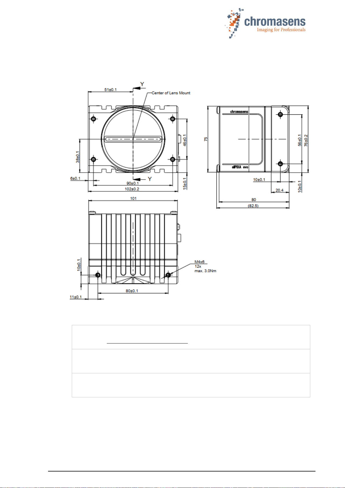
2.4.1Mechanical dimensions of the allPIXA evo 10k camera
Figure 2: Mechanical dimensions of the allPIXA evo 10k camera
NOTE I
Drawings and 3D-CAD-models are available on our homepage
http://www.chromasens.de/user
NOTE II
The shown position of the sensor surface is given as resulting optical value
including lengthening of the sensor glass. For more details, see section 2.5.
NOTE III
For information about the XYZ coordinate system and sensor alignment, see
section 2.5.
PMA_CHR_CD40195_R01_allPIXA_evo_UserManual.docx 14
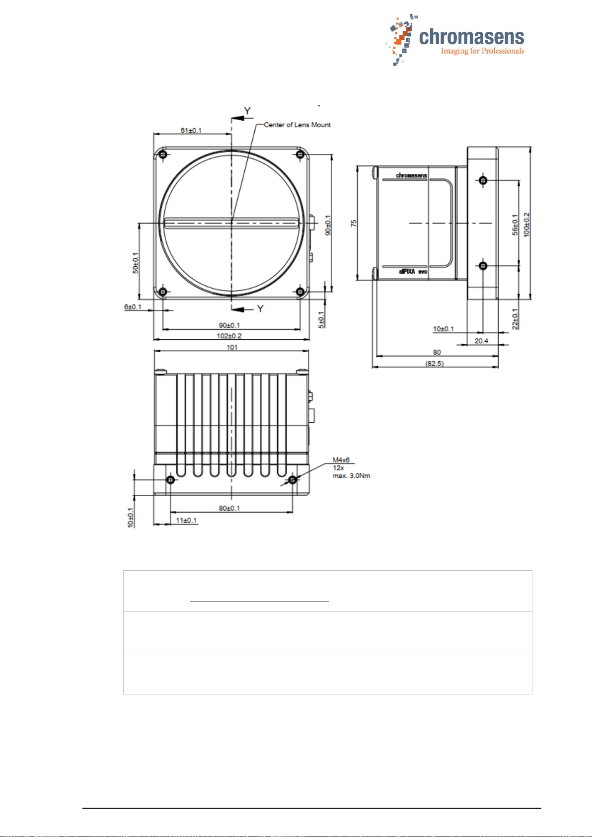
2.4.2Mechanical dimensions of the allPIXA evo 15k camera
Figure 3: Mechanical dimensions of the allPIXA evo 15k camera
NOTE I
Drawings and 3D-CAD-models are available on our homepage
http://www.chromasens.de/user
NOTE II
The shown position of the Sensor surface is given as resulting optical value
including lengthening of the sensor glass. For more details, see section 2.5.
NOTE III
For information about the XYZ coordinate system and sensor alignment, see
section 2.5.

PMA_CHR_CD40195_R01_allPIXA_evo_UserManual.docx 15
2.5 Sensor alignment and orientation
Sensor orientation and alignment in viewing from the front side of the camera. For a detailed
mechanical drawing, see section 2.4.
First pixel of sensor lines:
Left side
Color lines orientation:
Blue: top
Green: center
Red: bottom
Sensor alignment:
Position:
X: < +/- 100 µm
Y: < +/- 100 µm
Z: < +/- 100 µm
Rotation about:
Y: < +/- 0.1 °
Z: < +/- 0.1 °
Planarity of sensor surface:
< +/- 0.50 µm
Sensor window:
Thickness: 1.1 mm
Refraction index 1.5
Optical path extension: 0.37 mm
Figure 4: Sensor alignment
Sensor alignment is an important issue for:
•Adjusting multi-camera systems
•Replacing cameras
•Mechanical design of the mounting system for the camera
First pixel
X
Y
Z

PMA_CHR_CD40195_R01_allPIXA_evo_UserManual.docx 16
2.6 Adapter and accessories
2.6.1Lenses, adapters and mounts
Chromasens offers a large variety of accessories which are designed to provide maximum
flexibility and to get most out of the camera.
For the allPIXA evo cameras, special adapters are available that permit to use the accessories
of the allPIXA pro cameras.
You can find the complete list of all accessories including descriptions and detailed drawings in
the login area of our website at www.chromasens.de/user.
NOTE
For more information about accessories, refer to the corresponding accessories
catalogue.
2.6.2Cooling kit
To dissipate heat and thus reduce the housing temperature, a special cooling kit is available
that can be fixed to the camera, on the side and / or on top or bottom:
Figure 5: Cooling Kit for the allPIXA evo cameras
The distance of the mounting holes of the allPIXA evo housing are the same as for the allPIXA
wave camera. Therefore, the cooling kit of the allPIXA wave can be used:
Description
Identification No.
Pos.
allPIXA wave Cooling Kit B100
CP000540
01

PMA_CHR_CD40195_R01_allPIXA_evo_UserManual.docx 17
2.6.3Environmental requirements
Value
Temperature for camera operation
See section 2.3 for the allowed housing
temperature
Air humidity during camera operation
20% - 85% relative air humidity,
non-condensing
Storage / transport temperature
-20 ºC - +85 ºC; -4 °F - +185 °F
Protection category
IP50
General ambient conditions
Operation
IEC 721-3-3:IE33
Transport
IEC 721-3-2:IE21
Storage
IEC 721-3-1:IE11
NOTE:
You should use thermal conductive mounting (for example direct attachment
on metal frame) to decrease temperature and for improved camera
performance. See also section 5.4.

PMA_CHR_CD40195_R01_allPIXA_evo_UserManual.docx 18
3 Safety
3.1 Depiction of safety instructions
Safety-relevant information is indicated in this manual as follows:
WARNING
Indicates a potentially hazardous situation or task, which, if not avoided,
could result in serious injury or death.
CAUTION
Indicates a potentially hazardous situation or task, which, if not avoided,
may result in minor or moderate injury.
Indicates a potentially hazardous situation or task, which, if not avoided, could
result in damage to the product or the surrounding environment.
3.2 Basic safety regulations
The basic safety regulations always observe the following:
◼Do not attempt to install the device or start operation before you have read all supplied
documentation carefully and have understood its contents.
◼Safe and correct operation of the device requires correct and appropriate transport, storage,
mounting and installation as well as careful operation and maintenance.
◼Operation of the allPIXA evo camera device is only permitted if it is in a faultless and safe
condition. If a fault or defect occurs, the allPIXA evo camera, the machine, or the system in
which the allPIXA evo camera is installed, must be stopped immediately, and the responsible
person must be informed.
◼Modifications and extensions to the allPIXA evo camera are only permitted if the prior written
consent of Chromasens GmbH is obtained. This applies in particular to modifications and
extensions which can negatively affect the safety of the allPIXA evo camera.
◼Compliance with the ambient conditions described in this manual is essential.

PMA_CHR_CD40195_R01_allPIXA_evo_UserManual.docx 19
3.3 Safety instructions on the allPIXA evo camera
Risks from hot surfaces
The body of the allPIXA evo camera heats up during operation.
Do not touch hot surfaces without suitable protective gloves. Always allow
hot surfaces to cool down before carrying out any work on the unit.
Electric voltage hazard
The allPIXA evo camera runs with electric power. Before any work is carried
out on the allPIXA evo camera, be aware to disconnect the mains cables.
Make sure that the device is safely isolated from the power supply!
Risk of electrostatic discharge
The allPIXA evo camera contains components and units which are sensitive
to electrostatic charge.
Observe all precautionary measures for handling electrostatically sensitive
equipment.
Make sure that allPIXA evo camera, its corresponding tools, its equipment,
and the knowledge of the person who is handling it have the same electrical
potential.
3.4 Purpose / applications
◼The allPIXA evo camera is designed for machines and systems which are used for
commercial and industrial applications.
◼The owner of the machine or system in which the allPIXA evo camera has been installed is
responsible for compliance with relevant safety regulations, standards and directives.
Commissioning of the allPIXA evo camera is only permitted if the machine or system, in
which the camera is installed, complies with the safety regulations and standards of the
country in which the allPIXA evo camera runs.
◼The owner of the machine or system with the installed allPIXA evo camera must verify the
suitability of the allPIXA evo camera for its intended use.
◼Safety regulations of the country in which the device is used must be complied with it.
◼The allPIXA evo camera may only be connected or used as described in this manual.
◼The allPIXA evo camera must be set up and installed in compliance with the instructions
contained in this manual.

PMA_CHR_CD40195_R01_allPIXA_evo_UserManual.docx 20
3.5 Staff requirements
◼The system owner must ensure that all persons working on the system are trained for the
required work and have read and understood this manual. This applies particularly to the
employees who only work occasionally with the allPIXA evo camera, for example, during
commissioning and maintenance work.
◼Work on the electrical installation of the system may only be carried out by a qualified
electrician or persons who have undergone the necessary electrotechnical training under
the supervision of a qualified electrician, in compliance with applicable electrotechnical
regulations.
◼Be aware that only suitably trained and qualified persons are permitted to work with the
allPIXA evo camera. Such persons are qualified to work with the allPIXA evo camera device
if they are familiar with its assembly, installation, care, and all necessary precautionary
measures.
◼Assignments and responsibilities of the staff charged with operation, commissioning,
maintenance, and repair must be clearly defined and specified by the owner of the device
in which the allPIXA evo camera is installed.
3.6 Organizational measurements
◼The instruction manual must be stored safely in the vicinity of the camera in operation.
◼Information contained in this manual must be integrated into the documentation of the
device in which the allPIXA evo camera is installed.
◼The allPIXA evo camera and all connected peripheries must be checked regularly for visible
external damages.
3.7 Safety instructions for maintenance / cleaning
◼Before any service or maintenance work is carried out, the responsible staff has to be
informed.
◼Deadlines and intervals for regular inspections must be complied with.
◼Before maintenance is started, the allPIXA evo camera must be isolated from the power
supply.
◼Due to the risk of fire, devices such as radiators, heaters, or lighting equipment must be
allowed first to cool down.
◼Only technicians of the Chromasens GmbH are permitted to open or slacken screws or
housing sections of the allPIXA evo camera.
◼Necessary repairs may only be carried out by Chromasens GmbH.
◼Cleaning of the device is only allowed with a soft, lint-free cloth and Isopropanol (optional).
◼To avoid damages, the camera should only be transported in its original packaging.
This manual suits for next models
1
Table of contents
Popular Machine Vision System manuals by other brands


Advantech
Advantech VPS-3100 user manual

AXIOMTEK
AXIOMTEK RSC101 Series user manual

CIS
CIS VISION:mini VCC-G21X31ACL Product specification & operational manual

PhaseOne
PhaseOne RP1 1600 installation manual

TKH
TKH SVS-Vistek MotionBLITZ Cube6 manual

Daheng Imaging
Daheng Imaging MERCURY GigE Series user manual
