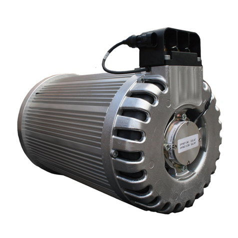
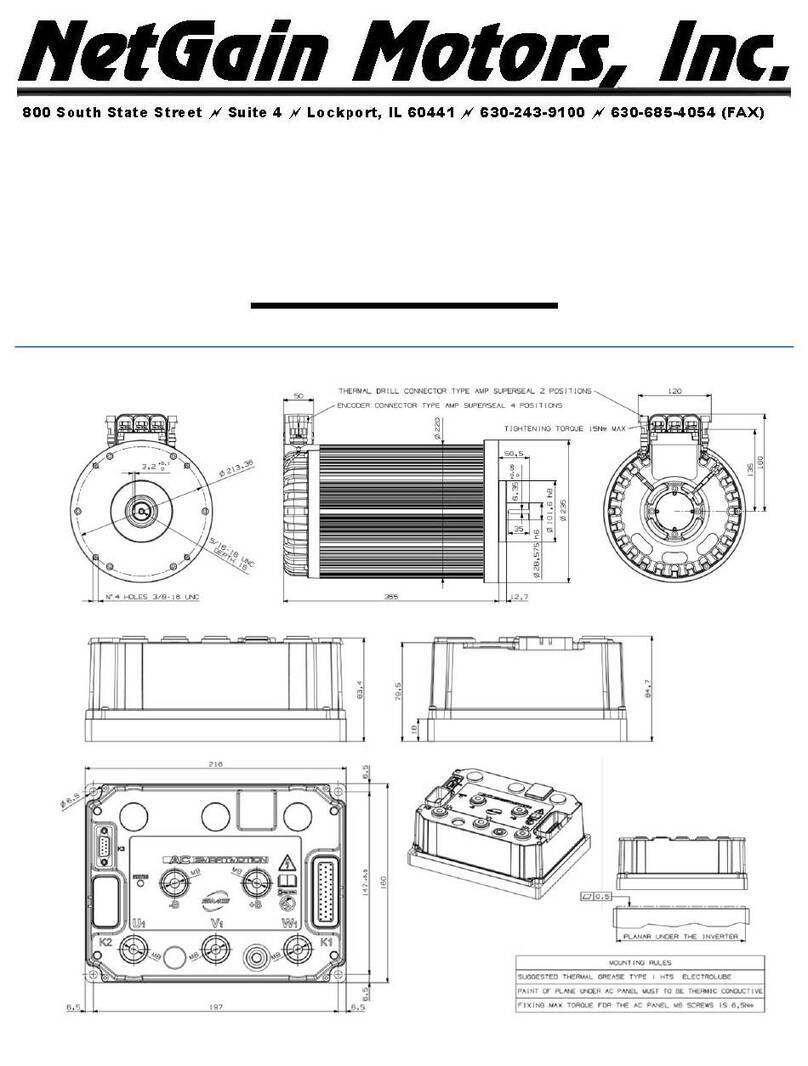
NetGain Motors ImPulse 8 User manual

Owner's Manual
for
and

Please record your motor serial number and date of purchase on this page.
Motor Serial Number: _________________________________________
Date of Purchase:_____________________________________________
Purchased From:______________________________________________
Motor Model:
OT ER
Waiver Of Liability & Indemnification
It is the responsibility of the purchaser to be familiar with the safe and correct installation and operation for all equipment.
he seller has no opportunity to supervise the application, installation, or maintenance of the components used, nor to
supervise and inspect the replacement of the motors used. herefore, the installer agrees that all motors will be used solely at
the purchaser’s risk. he purchaser will indemnify and hold the seller, its owners, and its employees or representatives free
and harmless from all loss, liability, or damage resulting from the alleged failure or defect of any project built using
components purchased from the seller.
April 18, 2017

RE: Your new NetGain Motors, Inc. DC Motor
It is with great pleasure that everyone at NetGain Motors, Inc.. welcomes you to the
AmP
™
and
WarP
™
motors
owner's family! We would also like to “Thank You” for your purchase.
Since electric motors are different from internal combustion engines, this Owner's Manual is
being sent to you to provide information on running and caring for your new motor. Please read
it carefully and follow the suggestions that will provide for years of great performance from
your new motor.
This Owner's Manual contains the new motor warranty, our dealer's safety information sheet,
wiring tips bulletin, heat and rpm protection bulletin, care and maintenance information sheet,
bench test procedure bulletin and other information of interest and importance. If you purchased
an AmP Motor your motor warranty will be provided by the Advanced Motors & Drives
Warranty. All other motors are covered by Warfield Electric Company, Inc.
There is also a substantial amount of content that may be obtained at our website:
http://www.go-ev.com
Along with your dealer, we definitely want to help make your EV project a success, so please
let us know if you have any questions about your motor, safety, wiring or anything else. We'll
help you or find resources that can help.
Again, we thank you for your motor purchase – we wish you success in your EV project!
WarP
™
Motors – TORQUE ABOUT IT!
George amstra
NetGain Motors, Inc.
President

WarP
™ Motors
WARFIELD NEW MO OR WARRAN Y *
WARFIELD ELECTRIC COMPANY, INC. (The Company), warrants that new motors sold by it are
merchantable and free of defects in material and workmanship at the time that they are shipped from the
company’s factory.
The company makes no warranty with respect to the new motors other than the warranty stated above. All
implied warranties of merchantability and all express and implied warranties of any other kind are hereby
excluded.
The company will repair or, at its option, replace any part of any new motor sold by it that fails to conform to the
warranty stated above, provided Warfield Electric Company, Inc. (factory) is contacted for a Repair
Authorization Number (RA#) and such part is returned to the company’s factory or to a factory authorized
service station, transportation charges prepaid, within the warranty period specified below:
NEW MOTOR WARRANTY extends for a period of one year or 2000 hours of
equipment operation, whichever first occurs, following the date of delivery of such
equipment into which the motor has been installed, but warranty coverage will not
exceed a period of two years from the date the motor was shipped from the company’s
factory. Proof of equipment installation date and equipment hour meter reading must be
provided.
LIMITATION OF LIABILITY
The company’s liability, whether in contract or in tort or under any other legal theory, arising out of warranties,
representations, instruction or warnings (or any lack or inadequacy thereof), deficiencies, failures or defects of
any kind or from any cause shall be limited exclusively to repairing or replacing parts (during normal business
hours) under the provisions stated above. All liability for damages, including, but not limited to, those expenses,
or injury to business credit, reputation or financial standing is hereby excluded.
The warranties contained therein shall not apply to or include any of the following and the company shall have
no liability with respect to:
1. Repair or replacement required as a result of: (A) accident; (B) misuse or neglect;
(C) lack of reasonable and proper maintenance; (D) operation in excess of
recommended capacities; (E) repairs improperly performed or replacements
improperly installed; (F) use of replacement parts or accessories not conforming
to Warfield Electric Company, Inc. specifications which adversely affect
performance or durability; (G) alterations or modifications not recommended or
approved in writing by Warfield Electric Co., Inc. and ( ) wear and deterioration
of motor appearance due to normal use or exposure.
2. Normal replacement of consumable service items, such as brushes and brush springs.
3. Motors in equipment whose ownership has been transferred from the first purchaser for use to another.
* No agent of Warfield Electric Company, Inc. is permitted or authorized to change, modify, or amend any term of this arranty.

R.A. Issued November 24, 2009
Rev A. April 20, 2010
6268 E. Molloy Rd – E. Syr cuse, NY Tel: (315) 434-9303 F x: (315) 432-9290
ADVANCED MOTORS & DRIVES, INC.
WARRANTY POLICY
1. Scope
The following document st tes the w rr nty policy of Adv nced Motors & Drives,
Inc. Kinetek division. Unless otherwise specified, the term “Adv nced Motors &
Drives” sh ll include the Unites St tes Kinetek division, its ffili tes of other Kinetek
divisions, nd their represent tives, officers nd employees. The w rr nty policy
describes Adv nced Motors & Drives, Inc. w rr nty oblig tions to its customers, the
limit tions of this policy, nd summ rizes the procedures reg rding submission of
w rr nty return cl ims, return of product, rejection nd receipt of reworked or
repl cement m teri l.
2. Limited W rr nty
Adv nced Motors & Drives, Inc. w rr nts to the origin l buyer (purch ser) of its
motors th t e ch of its products will be free from defects in workm nship nd
m teri l, during the W rr nty Period nd subject to Limit tions nd Exclusions s
deline ted in this document.
3. W rr nty Period
The W rr nty Period begins on the m nuf cturing d te of products shipped to the
user.
The b sic st nd rd W rr nty Period is of 1 (one) ye r or for the first 2000 (two
thous nd) hours of use, whichever occurs first.
A W rr nty Period longer th n 1 (one) ye r m y be w rded under contr ctu l
greements for specific Adv nced Motors & Drives, Inc. products, subject to
following Limit tions nd Exclusions.
If w rr nty cl im results in Adv nced Motors & Drives, Inc. repl cing the product,
then the W rr nty Period for the repl cement will be the rem ining unexpired
portion of the origin l W rr nty Period for the motor th t w s repl ced.
4. W rr nty Cl im Procedure
4.1 Customer must submit the w rr nty cl im within 30 (thirty) d ys of the
occurrence of the lleged non-compli nce or defect
4.2 Promptly upon customer’s communic tion, Adv nced Motors & Drives, Inc.
will provide Customer with Returned Goods Authoriz tion Number (RGA #)
AmP
™ Motors
AMD NEW MO OR WARRAN Y

R.A. Issued November 24, 2009
Rev A. April 20, 2010
6268 E. Molloy Rd – E. Syr cuse, NY Tel: (315) 434-9303 F x: (315) 432-9290
4.3 Customer must complete the Returned Goods Authoriz tion Form. Customer
must w it receipt of RGA # before returning the motor to Adv nced Motors
& Drives, Inc. Customer must properly identify the returned motor. Customer
will p y for the shipment of the returned motor.
4.4 Adv nced Motors & Drives, Inc. will w it the receipt of the motor before
processing the w rr nty cl im. If Adv nced Motors & Drives, Inc. determines
th t the returned motor is covered under the Limited W rr nty (item 2),
Adv nced Motors & Drives, Inc. will reimburse Customer for the ctu l cost of
shipment of the returned motor.
5. Determin tion of W rr nty Cover ge
5.1 As soon s pr ctic l, Adv nced Motors & Drives, Inc. will inspect the returned
motor to determine if the motor is covered under Limited W rr nty
provisions.
5.2 Approv l: If Adv nced Motors & Drives, Inc. pproves the w rr nty cl im, the
Customer will be reimbursed s deline ted in Item 6, Remedy.
5.3 Deni l: If Adv nced Motors & Drives, Inc. denies the w rr nty cl im, AMD will
promptly communic te the re sons of deni l of the cl im
5.4 If Customer dis grees with the determin tion, Adv nced Motors & Drives,
Inc. nd Customer will discuss the determin tion in good f ith nd solve the
w rr nty cl im mic bly. If the determin tion c nnot be resolved mic bly,
then Item 9 of the W rr nty Policy sh ll pply.
6. Remedy
6.1 Approved w rr nty cl ims: Adv nced Motors & Drives, Inc. will credit the
customer with n mount greed with the Customer nd not higher then the
origin l purch se price, or repl ce the motor free of ch rge, within 60 d ys of
the w rr nty cl im determin tion.
6.2 All credits issued under this Policy will be issued to the Customer’s ccount.
The Customer will not debit Adv nced Motors & Drives, Inc. without specific
written pprov l from Adv nced Motors & Drives, Inc. or Kinetek’s Controller
or Fin nce Officer.
6.3 The remedy s st ted under Item 6 provides for complete responsibility of
Adv nced Motors & Drives, Inc. for ll w rr nty cl ims for non-compli nce, or
defects.
7. Limit tions nd Exclusions
7.1 The Limited W rr nty pplies exclusively to motors th t h ve received norm l
use nd service, nd their pplic tion w s pproved by Adv nced Motors &
Drives, Inc. before purch se.
7.2 The Limited W rr nty does not pply to: ). ny motor th t w s dism ntled,
rep ired or ltered without prior consent from Adv nced Motors & Drives,
AmP
™ Motors
AMD NEW MO OR WARRAN Y

R.A. Issued November 24, 2009
Rev A. April 20, 2010
6268 E. Molloy Rd – E. Syr cuse, NY Tel: (315) 434-9303 F x: (315) 432-9290
Inc. ; b) f ilure of the motor w s the result of improper inst ll tion, vehicle
ccident or misuse.
7.3 The Limited W rr nty does not pply to component p rts th t re subject to
we r, for ex mple be rings, brushes or se ls.
7.4 This Limited W rr nty does not cover ny d m ge to the vehicle,
compens tion for loss of time or inconvenience, nd does not provide for ny
li bility for incident l or consequenti l d m ge rising from the use of the
motor by its buyer, its ssignees, Customers, gents or employees.
8. Discl imer
Except for the Limited W rr nty set forth bove, Adv nced Motors &
Drives, Inc. m kes no other represent tion or w rr nty, expressed or
implied, rising by oper tion of l w or otherwise, with respect to ny
product including, without limit tions, the w rr nties of merch nt bility
nd fitness for p rticul r purpose whether or not the use or purpose h s
been disclosed in specific tions, dr wings or otherwise, nd whether or
not ny product if specific lly designed nd/or m nuf ctured by Adv nced
Motors & Drives, Inc. for the Customer’ s use or purpose. The w rr nty set
forth bove is given in s tisf ction of ny nd ll oblig tions or li bilities
of Adv nced Motors & Drives, Inc. to ny Customer, or ny third p rty,
with respect to the product, whether such li bilities or oblig tions rise
out of contr ct, negligence, strict li bility, tort or otherwise. Adv nced
Motors & Drives, Inc. sh ll not be li ble for ny property d m ge or
person l injury to ny Customer or third p rty, with respect to the
product. Adv nced Motors & Drives, Inc. sh ll not be li ble to ny
Customer or ny Customer’s owners, officers, gents, employees, or
subcontr ctors, or otherwise for ny indirect, consequenti l, incident l,
speci l, punitive or exempl ry d m ges including without limit tion
d m ge or loss of profits or revenues, even if Adv nced Motors & Drives,
Inc. h s been dvised of the possibility of such d m ges.
9. Dispute Resolution
The interpret tion, perform nce nd completion of ll tr ns ctions under the Limited
W rr nty Policy sh ll be governed by the L ws of the St te of New York, without
reg rd to or pplic tion of its principles, procedures or l ws reg rding conflicts of
l ws.
AmP
™ Motors
AMD NEW MO OR WARRAN Y

AmP
™
& WarP
™
Motors
Safety Information
his is not an all inclusive list. Use common sense and act responsibly, electric motors are extremely powerful and
could cause death, dismemberment or other serious injury if misused or not safely handled!
Use caution when operating any motor. If you're not sure what you're doing, find a knowledgeable person to
advise you!
Remove all metal jewelry and metal objects from hands, wrist, fingers, etc. before working on any electric motor.
If working on an electric vehicle, make certain the vehicle is positioned securely with the drive wheels safely clear of
the floor and blocked up so that the drive wheels cannot make contact with the floor under any circumstances.
Block the non-drive wheels if they remain in contact with the floor so that the vehicle cannot roll in either direction.
Before troubleshooting or working on any electric vehicle, disconnect the battery and discharge all capacitors.
Reconnect the battery only as needed for specific checks or tests.
Motors must only be connected to a power source by knowledgeable and experienced personnel.
Motors should NEVER be run without a load. Running a motor without a load could result in harm to people or
the motor. Absence of a load is considered misuse and could prove dangerous to anyone in the vicinity and void the
motor warranty.
Portions of the motor may become hot and proper precautions must be taken.
Motors are heavy and are likely to become damaged if dropped, or cause damage to anything they fall upon
(including people and body parts). Use extreme caution when working with motors!
Make certain the motor is disconnected from any power source before servicing.
Motors contain moving parts that could cause severe injury if the proper precautions are not taken. Never touch
an operating motor.
Motors should never be operated beyond the limits established by the manufacturer.
Motors must not be modified in any manner; doing so will void the motor warranty and could prove extremely
dangerous.
Wear protective or safety equipment such as safety shoes, safety glasses and gloves when working with motors.
Make sure you know where the closest functioning eye wash station is before working on or testing batteries.
Do not defeat any safety circuits or safety devices.
Under no circumstances should you push in any contactor of an electric vehicle while the drive wheels are in
contact with the floor. Pushing in a contactor when the drive wheels are in contact with the floor can cause serious
property damage, personal injury or death.

AmP
™
&
WarP
™
Motors
Information
NetGain Motors, Inc's.
AmP
™and
WarP
™motors are produced by some of the nation's largest
builders of series wound DC motors. Matching their experience and knowledge with our engineering
and racing experiences, makes a perfect team to design motors that will perform under the unusual
operational dynamics of electric vehicles.
All aspects of an electric motor were considered - from the components to the methodology of assembly
- to make a motor that would perform in an electric vehicle.
Electric motors components are very critical in an electric vehicle, as are voltage and amperage, range,
bearings, shaft sizing, commutator and brush coordination, windings and temperature range. Assembly
steps critical to performance are clearances, brush “break-in”, lacquering/baking process and overall
quality of workmanship.
One area of serious study has been temperature. Where most DC motors are made to meet class F
temperature rating (155º C.), our
AmP
™
and
WarP
™motors all exceed class ratings (180º C.) (Our
WarP
™motors have been stress tested to 205º C). Whether using your DC motor for drag racing or
for an everyday EV, temperatures will normally never approach 180º C. owever, an external high
volume fan or blower can be very effective in further dissipating motor heat, and additionally clears
carbon dust from the brushes, which reduces risk of flash-over and would-be damage.
AmP
™and
WarP
™motors
are designed with an internal fan to provide cooling and motor protection
during normal operation. All
AmP
™and
WarP
™motors are also configured with a temperature snap
switch as a standard item (normally open) for early warning of an overheating situation. The snap
switch is set to open at 120º C (150º C for 11" & 13" motors) and can drive an indicator light or warning
tone in your vehicle or automatically close a circuit in your vehicle if it indicates overheating.
Motor ratings are given for the normal range of the motor's operation under various voltages and loads.
Ratings with forced cooling have not been done since there are too many variables that cannot be
controlled to allow the data to be useful. Needless to say, the motor will perform closest to its initial P
output the cooler one can keep it!
Some larger DC motors have interpoles. Because of the compactness of most motors 9” or less in
diameter, in these horsepower ratings, interpoles cannot fit inside. Our
WarP 13
™and
WarP 11
™
motors can have interpoles added, but they are not the standard configuration.
Lastly, please remember that
AmP
™and
WarP
™motors offer distinctive standard features on every
motor that we feel make it the best choice for an electric vehicle motor in the industry. Some of these
features are:

Standard
AmP
™
and
WarP
™
Motors Features
✔Specifically designed for street and racing EVs
✔Top quality, sealed, steel bearings with high temperature grease
✔Motor temperature snap switch
✔Brush Wear Indicators (on some models - eff. 4/2007)
✔igh efficiency fan
✔Optimized brush timing
✔Oversize brushes
✔igh quality brushes- not “quick-seat”
✔Fully 90% plus brush wear-in1
✔eavy duty, vibration resistant, stainless steel brush springs
✔Pre-drilled advanced timing holes for higher performance
✔Insulation that exceeds Class “ ” temperature rating
✔Best in class patented varnishing process
✔Voltage ranges starting at 48 Volts
✔Interlocking commutator construction
✔igh peak motor efficiency
✔Dynamically balanced armatures
✔and made in the U.S.A. by experts
1 The brush wear-in process is completed before the brushes are placed into the enclosure so that no carbon dust is allowed into the
motor.

IMPORTANT MOTOR INSTALLATION AND OPERATIONAL INFORMATION
PLEASE READ CAREFULLY
•BEFORE POWERING T E MOTOR T E FIRST TIME BE SURE TO C ECK AND ENSURE
T AT BOLTS ARE NOT OBSTRUCTING T E FAN BLADES! FAN BLADES T AT ARE
S EARED OR DAMAGED BY USING BOLTS T AT ARE TOO LONG ARE NOT COVERED BY
WARRANTY, NOR IS ANY SUBSEQUENT DAMAGE T AT MAY OCCUR TO T E MOTOR!
TURN T E MOTOR BY AND TO ENSURE IT TURNS FREELY AFTER SECURED TO T E
ADAPTER PLATE.
•NEVER RUN T E MOTOR WIT OUT A LOAD AT MORE T AN 12 VOLTS! DOING SO
COULD CAUSE T E MOTOR TO SELF DESTRUCT AND IS NOT A CONDITION T AT IS
COVERED UNDER WARRANTY! NEVER REV T E MOTOR UP W EN IN NEUTRAL OR
W EN T E CLUTC IS DEPRESSED.
•NEVER USE YOUR BRAKE AND T ROTTLE PEDAL AT T E SAME TIME. T IS COULD
POTENTIALLY STALL T E MOTOR AND CAUSE IT TO BURN T E COMMUTATOR AND
WILL VOID T E WARRANTY.
•NEVER USE T E T ROTTLE PEDAL TO OLD YOUR VE ICLE ON A ILL, T IS WILL
STALL T E MOTOR AND CAUSE IT TO SCORC T E COMMUTATOR AND WILL VOID T E
WARRANTY.
•A STALLED MOTOR WILL DRAW AS MANY AMPS AS IT CAN AND RESULT IN RAPID
OVER EATING OF T E COMMUTATOR AND WILL VOID T E WARRANTY.
•A STALLED MOTOR WILL NOT BE COVERED BY WARRANTY. STALLING WILL BURN T E
COMMUTATOR BARS AND IS CLEARLY VISIBLE DURING INSPECTION FOR WARRANTY.
•WARM COMMUTATORS CANNOT WIT STAND T E SAME RPMs T AT A COOL
COMMUTATOR CAN. UNDER COOL CONDITIONS T E MOTORS S OULD NOT BE SPUN
BEYOND 5,000 TO 5,500 RPMS, LOWER W EN T E COMMUTATORS ARE WARM.
•MOTORS S OULD IDEALLY BE RUN IN T E 2000-3500 RPM RANGE FOR PROPER COOLING
AND EFFICIENCY. YOU S OULD NOT REMOVE OR OBSTRUCT T E AIR INTAKES OR
EX AUST. REMOVAL OF T E FAN WILL VOID T E WARRANTY.
•BOLTS INSERTED INTO T E LIFT-EYE OLES MUST NOT TOUC T E FIELD POLE S OES!
•T E FIELD POLE BOLTS IN T E CASE S OULD NEVER BE REMOVED OR USED TO
SECURE ANYT ING.
•YOU S OULD NEVER WELD ANYT ING ONTO T E CASE. DOING SO CAN OVER EAT
T E ISULATION AND CAUSE PREMATURE FAILURE OF T E MOTOR.

Date: April 13, 2005
To: All
AmP
™and
WarP
™Motors
Dealers
Subject:
AmP
™and
WarP
™ Motors
Wiring (except
WarP 13
™ )
Several sources have recently inquired as to what the proper method was for wiring the terminal lugs on
the cases of
AmP
™ and
WarP
™ motors . This
Special Update
clarifies the proper wiring method.
All
AmP
™ and
WarP
™ motors cases have four terminals, A1, A2, S1, S2 stamped on the case at the
factory. Motors are designed to normally operate in Counter Clock Wise rotation at the Drive End (CCWDE )
for forward vehicle operation. When a motor is specified as “advanced timing”, it is assumed to be relative to the
normal CCWDE rotation. Motors that do not have advanced CCWDE timing may be wired for Clock Wise
rotation at the Drive End (CWDE ). Advanced timing is alos referred to as “favored” timing. These instructions
should help clarify the proper wiring method for both rotations.
AmP
™ and
WarP
™ motors (except the
WarP 13
™ ) should ALL be jumpered according to these
instructions (battery polarity does not matter):
For CCWDE rotation wire as follows: *
CCWDE preferred connection method:
Connect A1 to S1
Connect A2 to one input power terminal and S2 to the other input power terminal
CCWDE alternative connection method:
Connect A2 to S2
Connect A1 to one input power terminal and S1 to the other input power terminal
For CWDE rotation wire as follows:
CWDE connection method:
Connect A1 to S2
Connect A2 to one input power terminal and S1 to the other input power terminal
CWDE alternative connection method:
Connect A2 to S1
Connect A1 to one input power terminal and S2 to the other input power terminal
Motors that have “advanced timing ” for CCWDE rotation should not be run in CWDE mode. Doing so may
damage the motor and void the warranty.
*Dealers may request a motor be timed advanced for CWDE operation by specifying this on their Purchase Order. This will be
considered a “Special Order” and may involve an additional cost.

Date: October 24, 2006
To: All
WarP
™ Motors Dealers
Subject:
TransWarP 11
™ Motor Wiring and errata*
Normal wiring for Counter Clockwise Rotation when viewed from the Drive End (CCWDE) of a
WarP
™ ,
ImP lse
™ or
TransWarP 9
™ motor is: A1-S1 or A2-S2.
owever, on the
TransWarP 11
™ the wiring for CCWDE is: A1-S2 or A2-S1. For CWDE the wiring on
these motors is A1-S1 or A2-S2.
Additionally, all of the NetGain Motors, Inc.. 11-inch and 13-inch motors incorporate a 150° C snap switch.
Other motors utilize a 120° C snap switch.
Wiring information for other
AmP
™ and
WarP
™ motors may be found in the
Special Updates
dated
04/13/2005 and 03/01/2006.
You may locate copies of these and all other
Special Updates
on our Web Site at:
http://www.go-ev.com/dealers-only/Dealer_Manual
All motors produced in 2007 will incorporate 2 lifting holes to aid installation. These holes will be positioned
90 degrees apart in order to allow better positioning of the terminal studs.
Broken fins, which occasionally occurred on
ImP lse 9
™ and
WarP 9
™ motors due to the placement of
advanced timing holes, will now be machined during assembly.
Dealer input is always welcomed, if you have any suggestions on how we might improve our motors, please
contact us! 04/13/2005 and 003/01/2006.
You may locate copies of these and all other
Special Updates
on our Web Site at:
http://www.go-ev.com/dealers-only/Dealer_Manual
* Beginning in 2008, all new
TransWarP 11
™ motors
will be produced so they are wired identical to all other
WarP
™ motors. If
you purchased your motor prior to 2008 you should verify correct rotation prior to installation!

Date: February 13, 2006
To: All
AmP
™ and
WarP
™ Motors Dealers
Subject:
AmP
™ and
WarP
™ Motors eat and RPM Protection Bulletin
Throughout the year we have had inquiries about the effects of heat and RPM's on
AmP
™ and
WarP
™
motors. This
Special Update
summarizes many of our conversations with individual dealers and shares the
same knowledge across our entire dealership network. As in our other
Special Updates
, this information does
not cover every aspect of the motor's usage. If you have a situation that you are unsure about, please call
someone that has the expertise or seek more detailed information. Please act responsibly and protect yourself
and your customer from personal harm or damage to the motor.
Motor Heat
1. All
AmP
™ and
WarP
™ motors are rated over Class , which is 180 degrees C, but one still
needs to protect the motor from overheating
2. If you are using your motor for drag racing, with 10-20 seconds of high load, the brushes and comm will
heat up faster than the other parts of the motor. To protect your motor in this case, measure temperature
in the brushes and the comm surface area using an infrared device that can react quickly. eat can build
very fast, as you would expect and may already know!
3. If your motor is used for normal vehicle travel, the ends of the pole shoes and the motor case by the shoe
bolts will generally be the area of greatest heat build up. To protect your motor in this area, the normal
temperature snap switch is installed. Connect it to give the driver a warning light or to automatically
open the circuit if it indicates overheating. eating will build slower here, but fast action needs to be
taken to protect the system.
4. Consider setting a temperature of 110-120 degrees C for your action starting point as a safe way to
manage a potential overheating situation.
5. Lastly, always ensure that sufficient and proper air circulation through the motor is not impaired!
Motor RPM
1. All
AmP
™ and
WarP
™ motors have commutators that were tested to over 8,000 RPM, but that
does not mean they can be run at that speed indefinitely!
2. Most motor commutators built now are composite. Steel commutators were used in the past, but are now
made for custom orders and very expensive. Steel core commutators are generally able to withstand
higher RPM speeds.
3. We like to recommend safe speed ranges from 2000- 3500 RPM, even though we know some of our
AmP
™ and
WarP
™ motors are peaked around 5,000 RPM for small intervals of time. When
working with a customer, please be sure to design gearing so that the customer gets the speed he wants,
but the motor will not be at a high RPM for long periods of time.
4. Lastly, utilize one of the many ways available to protect the motor from exceeding 8,000 RPM and make
sure it is installed and working properly. It just needs to work once to pay for itself, save the motor and
protect all the people around the vehicle!

Date: February 15, 2006
To: All
AmP
™ and
WarP
™ Motors Dealers
Subject:
AmP
™
and
WarP
™ Motors Care and Maintenance
This
Special Update
summarizes many responses we have given to dealers and customers
alike about motor care and maintenance. As the sphere of users continues to grow for electric
motors used in vehicles, knowledge about motors needs to be communicated to all those users
across our entire dealership network. As in our other
Special Updates
, this information does
not cover every aspect of the subject.
ere are a few simple steps one should take to help the
AmP
™ and
WarP
™ motors
provide
years of great performance.
1. Protection from the elements is important. Utilize good design concepts and materials to
protect the motor from rain, snow and ice.
2. Design the motor mounting area to allow for good air flow. The motor needs a continuous
supply of clean fresh air to cool properly.
3. Protect the motor from “dirty air” that may be used to cool it. Most airborne grit will act
as an abrasive, which will eventually cause harm to the internal parts of your motor.
4. Clean the brushes and comm area regularly from the dust/dirt that occurs during normal
operation.
5. Regularly check connections, voltages, tolerances and alignment to assure they are within
normal specifications.
6. If you suspect or question the motor's operation, immediately shut it down. Record any
visual signs, audio sounds or scents at the time and ask an expert for an opinion prior to
operating the motor again.
7. Always operate the motor within the normal safety ranges for voltage, amperage and
RPM
8. Follow all the safety rules available to you.
9. Remember your motor will take care of you, if you take care of it.

1
AmP
™ and
WarP
™ Motors
Series Motor Bench est Procedure
( est at 12 volts ONLY)
CAU ION! Read completely!
Caution!!!!
Sparks can ignite gases emitted from batteries!
Use quick-connect cables for battery and motor!
DO NO HARDWIRE MO OR AND BA ERY
CONNEC IONS!
Make certain that the motor is securely strapped or
bolted in position. The motor must not be allowed to move!
If a battery is used instead of a charger, the battery must be at least 20 feet away from the motor in a well
ventilated area or preferably outside of the building!
The cables MUS be connected and disconnected in the order shown!
Connecting sequence:
1. Connect cable #1 and cable #2 first.
2. Connect cable #3, to power source positive terminal (+) at the power source first, NOT at the motor.
3. Connect the other end of cable #3 to terminal (A1) at the motor which is 20 feet away from the power
source.
4. Disconnecting sequence:
5. Disconnect cable #1 first. (This deactivates the motor)
6. Disconnect cable #2 and then #3 from the power source.
Heavy Duty Charger
S2
-
S1
A2
A1
12 volt
23
.
.
.
20 feet
.
.
.
Y
<
Y
>
Power source
+

Selecting EV Components
he Vehicle
There are numerous factors to consider in trying to select the appropriate components for a particular
conversion product, and they go hand-in-hand. The intended user of the vehicle should first define their
intended application. Some people define “performance” as being able to achieve the greatest range with their
vehicle. Others may define performance as achieving a particular speed in a specific time. It is important to
determine what the performance goals are for a vehicle before choosing the vehicle. If someone is looking for
range and chooses a vehicle for conversion that does not have room for batteries, they will likely be
disappointed in the end result. Similarly, if someone is looking for the quickest 0-60 miles per hour time and
selects a heavy vehicle they might also be disappointed. Knowing the performance expectations can help
determine an appropriate vehicle for conversion.
An ideal vehicle is one that has the existing braking capacity, as well as the suspension capacity to handle the
weight of the batteries and other components installed during the conversion.
It is advisable to measure the height to the top of each wheel opening on the vehicle before any conversion is
undertaken. Ideally, this should be the height after the conversion is completed. Obtaining the proper ride height
and suspension travel is crucial to the vehicles handling and safety. It may be necessary to have a company that
specializes in suspension suggest alternatives after the vehicle has been converted.
In some cases a vehicle that is already owned is chosen for conversion simply because the customer already
owns it. It may not be an appropriate vehicle, but the decision has already been made.
he Batteries
The rule-of-thumb when using lead-acid batteries for a conversion is that the vehicle will end up weighing
about 1,000 lbs more than it did before the conversion and usually have a range of 20-30 miles. Certainly, some
people have converted vehicles with 50+ mile ranges using lead-acid, but the extra range comes at the expense
of load carrying capacity. It is best to know and consider the effect of adding 1,000 lbs of weight will have on
the vehicles handling and braking capacity.
Besides the weight of the lead-acid batteries, the voltage is known to sag severely during heavy amperage draw.
Lead-acid (PbA) battery range may be cut in ½ during cold weather. The typical life of PbA batteries is
normally around 2-3 years in an EV application. The normal “starting” batteries used in ICE vehicles are
generally not considered a good candidate for EV's as they usually cannot handle the heavy charge and
discharge cycles. The most commonly used PbA battery are the golf-cart style batteries. But, these “flooded”
batteries will require constant checking of the electrolyte levels, and they generally cannot deliver the amperage
required in modern EV's. Flooded golf-cart style batteries can provide the best range of PbA batteries, and their
life can be 4+ years if properly maintained. This does come at the cost of a lot of weight.
Lighter and more powerful PbA batteries known as “absorbed glass mat”, and even better “spiral wound”
batteries will allow higher amperage draws, but the range will typically be around ½ of what the large flooded
batteries will deliver. But these types of batteries can generally deliver higher amperage over a longer period
than flooded type batteries.
Whenever economically feasible, Lithium Iron (LiFePO4, LiYFeSO4, or similar) battery chemistry should be
considered. Besides the improvement in the amperage that can be delivered, the LiFe batteries are not nearly as
sensitive to cold weather or high temperature, and the voltage does not sag as deeply under heavy amperage
DRAF VERSION 1.1 Tue, April 18, 2017 - Copyright© 2015 ,2016,2017 All Rights Reserved, NetGain Motors, Inc. Page 017 of 34 Pages

Selecting EV Components
draw. It is not unusual for someone to have a Li powered vehicle that has a 70-90+ mile range, and perform
very well. In part the improved performance is due to the much lower weight of the Li batteries, but also due to
their ability to supply high amperage.
he Controller
In most vehicles being converted a 1,000 Amp or higher controller should be considered. Certainly, 500 Amp
controllers have worked well for many years, and since the older style PbA batteries may have only been
capable of 300 Amps discharge, a 500 Amp controller was sufficient. Indeed, if a vehicle only requires 150
Amps to travel at it's average speed, so the use of a 1,000 Amp controller will not offer any advantages –
EXCEPT at start-up! And, the difference between 500 Amps and 1,000 Amps at start-up can be quite
significant with most motors capable of close to 4 times the torque at 1,000 Amps that they produce at 500
Amps. LiFe batteries exist today that can discharge 4,500 Amps, and the potential of these batteries is
improving rapidly.
If you have a heavy vehicle, you need the higher amperage controllers. Often times, people think it is easier on
a motor to only provide it 500 Amps rather than 1,000 Amps. Though 500 Amps will produce less heat than
1,000 Amps, you must take into consideration whether the amperage will provide the necessary torque the
motor needs to start rotating. If the amperage isn't high enough to start the armature spinning, all of the 500
Amps will be split between just a couple of commutator bars. If the armature doesn't turn it is considered a stall
condition, and the heat build-up can quickly cause a commutator bar to raise. A stall condition is not covered
under warranty, and the condition is quite easily determined by the scorch marks 90 or 180 degrees apart on the
commutator.
The speed that the vehicle will be able to obtain is determined (in part) by the voltage that is delivered to the
motor – not necessarily by the voltage that is delivered to the controller. When a new off-shore manufacturer of
controllers entered the market a few years back, we were swamped by calls from users of this new 120 Volt
1,000 Amp controller who could not get their vehicles over 30 MP . Users naturally accused the motor of not
being able to power their vehicle, when the actual cause of the problem was that the controller was only able to
deliver 36 Volts to the motor. Volts = RPMs in a nearly linear manner with series wound motors. If the voltage
to the motor doubles, the motor RPMs will double. Since most losses are fixed, the RPMs may increase slightly
more than double.
EV racers found it necessary to build 336 Volt + battery packs due to the fact that 12 Volt PbA batteries would
sag to 5.5 Volts when 1,400 Amps were drawn from them. If the motors are capable of handling 168 Volts, and
the PbA battery pack is 168 Volts nominal, then the motor would only see about 77 Volts when 1,400 was
drawn from the battery pack. In order to deliver the maximum voltage to the motor, it became necessary to
increase the PbA battery pack voltage. As LiFe chemistry battery voltage typically sags far less under heavy
amperage draws (25% vs 50%), the battery pack voltage need not be as high as a comparable PbA battery pack
voltage.
he Motor
Matching all the components of an EV is a critical aspect of any conversion. Choosing batteries that can't
discharge high enough current may mean that the controller won't be able to supply the motor with the
amperage it may need for a particular job. Choosing a controller that can't supply the motor with the current it
needs to perform will likely result in a conversion that doesn't meet expectations. Choosing a battery pack that
is too low a voltage may limit the speed the vehicle is able to attain. Choosing a motor that is too small for a
DRAF VERSION 1.1 Tue, April 18, 2017 - Copyright© 2015 ,2016,2017 All Rights Reserved, NetGain Motors, Inc. Page 018 of 34 Pages

vehicle will lead to the motor heating up and being overworked and possibly leading to motor failure. Choosing
a motor that is too big for an application may lead to the motor “lugging” which will normally result in
Selecting EV Components
commutation problems over time, and eventually to other motor problems.. For the best electric vehicle
experience, it is essential that the electric motor be carefully sized to the vehicle for which it is intended. Simply
using a “bigger motor” for a larger or heavier vehicle is not necessarily the best way to match components.
Likewise, choosing a motor that is simply too small for an intended application is also likely to end up with an
undesired result as the motors may overheat.
Many factors are used to determine which motor is suitable for the weight (and aerodynamics) of the vehicle to
be propelled and the speed which is to be maintained. There are some online tools which can tell you how a
vehicle might perform under varying conditions, such as: http://www.evconvert.com/tools/evcalc/ But, even
excellent tools such as this cannot take all the various battery, controller, and motor options into account.
NetGain Motors, Inc. is will assist Authorized Motor Dealers or their customers in trying to size the right
motor for their particular application, however we prefer to provide the Authorized Motor Dealer with the
information so that they remain the primary point of contact with the customer. In order to assist Authorized
Motor Dealers in motor selection, we need to be provided with as much of the following pieces of information
as possible:
•Battery Pack Information
◦Voltage
◦Internal resistance
◦Discharge capabilities
•Motor Controller
◦Voltage capabilities
◦Amperage capabilities
•Vehicle Characteristics
◦Vehicle weight (after conversion)
◦Top speed to be maintained on level terrain
◦Top speed to be maintained on grade
◦% grade
◦Gear ratios of transmission
▪Gear efficiency
◦Rear differential gear ratio
◦tire diameter
▪Type of tire/surface (i.e. rubber on concrete)
◦Coefficient of drag
◦Frontal area
It is possible that the customer will have unrealistic goals, objectives, or understanding of a technology they are
unfamiliar with. It is unlikely that you could suggest a motor combination that would provide a 0-60 MP of
2.9 seconds and a top speed of 250 MP with direct drive in a 4,000 lbs vehicle at 48 Volts.
Direct driving a vehicle with an electric motor sounds simple, and it is the first thing that many people believe
they want. owever, to properly direct drive a vehicle considerations must be given to the safety of the vehicle
and the workmanship of the conversion. A mistake in wiring a direct drive conversion leaves little room for
DRAF VERSION 1.1 Tue, April 18, 2017 - Copyright© 2015 ,2016,2017 All Rights Reserved, NetGain Motors, Inc. Page 019 of 34 Pages

mistakes. It is unlikely that the brakes of the vehicle would be sufficient to stop an electric motor receiving full-
power. Without a manual disconnect (such as a clutch, or neutral transmission gear), it could prove extremely
dangerous or fatal for the driver and occupants of the vehicle or even bystanders. There are benefits to direct
drive, in that the normal transmission losses may be eliminated. This is useful when racing, but offers little
benefit to a “daily driver” type of vehicle. Although direct drive works well for racing, it is not advisable for
around town driving as the motors should normally spin 2000 - 4000 RPMs in order to properly cool. Forced
air cooling is highly encouraged to help cool direct drive motors, as well as vehicles that are used in stop and go
(around town) driving.
There are also significant drawbacks to the use of direct drive vehicles, beyond just the safety issue. Direct drive
will normally require twice the motor and twice the controller of a vehicle with a transmission (a 2000 Amp
controller rather than a 1000 Amp controller) Either a larger motor will be needed for direct drive, or a second
motor which will add additional weight and consume additional space will be needed. This will normally offset
the customer's expected savings of a direct drive configuration. Additionally, dual motors will require a more
complicated wiring scheme in order to allow for reverse direction movement of the vehicle. Dual motor direct
drive also decreases the overall electrical efficiency of the system slightly.
The motors enjoy spinning at 2,000 - 4,000 RPMs. You should always design your conversion so that the
normal operating RPMs of the motor are within this range. You may accomplish this by modifying the gear
ratios (transmission and rear differential) and tire diameters. In general, the electric motors prefer spinning
about 1,000 RPMs higher per gear than the original internal combustion engine did.
PbA Battery Vehicle
Direct Drive Motor Selection2
Motor
Vehicle Weight
Dual Coupling Motor
Vehicle Weight
TransWarP 7
™
~1,400 lbs
WarP 7
™
~2,800 lbs
TransP lse 9
™
~1,600 lbs
ImP lse 9
™
~3,200 lbs
TransWarP 9
™
~1,750 lbs
WarP 9
™
~3,500 lbs
TransWarP 11
™
~2,100 lbs
WarP 11
™
~4,200 lbs
TransWarP 11HV
™
~1,900 lbs
WarP 11HV
™
~3,800 lbs
The use of a transmission normally allows you to double the figures of the first table:
PbA Battery Vehicle
ransmission-ed Vehicle Motor Selection
Motor
Vehicle Weight
WarP 7
™
~2,800 lbs
AmP 8
™
~3,200 lbs
ImP lse 9
™
~3,200 lbs
WarP 9
™ or
Amp 9
™
~3,500 lbs
WarP 11
™
~4,200 lbs
WarP 11HV
™
~3,800 lbs
2 Direct Drive assumes that a differential with additional gearing is still being utilized.
DRAF VERSION 1.1 Tue, April 18, 2017 - Copyright© 2015 ,2016,2017 All Rights Reserved, NetGain Motors, Inc. Page 020 of 34 Pages
This manual suits for next models
14
Table of contents
Other NetGain Motors Engine manuals
