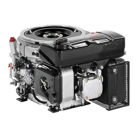
NetGain Motors HyPer 9 IS User manual

HyPer 9 IS User Manual Revision 06
NetGain Motors, Inc.
Page 1 of 27
User Manual
HyPer 9 IS™

HyPer 9 IS User Manual Revision 06
NetGain Motors, Inc.
Page 2 of 27
Table of Contents
Warning and Caution ..............................................................................................................................................................4
Safety Information ..............................................................................................................................................................4
DISCLAIMER: .......................................................................................................................................................................5
X1 Wire Harness K1 Pinout Serial #’s H9000001-H9000105...................................................................................................6
X1 Main Wiring Diagram.........................................................................................................................................................7
................................................................................................................................................................................................ 7
HyPer 9 Motor Plug Pinout .....................................................................................................................................................8
Motor Encoder Pin Positions .............................................................................................................................................. 8
Motor Thermistor Pin Positions..........................................................................................................................................8
X1 Main Contactor Wiring.......................................................................................................................................................9
24/48V Coil Driver, High Voltage Contacts, and Key Switch In...........................................................................................9
Compact Display Pinout........................................................................................................................................................10
Compact Display Mating Female Plug...............................................................................................................................10
Pre-startup Steps ..................................................................................................................................................................11
Download SME SmarView Sys Program:...........................................................................................................................11
Download* the Latest Controller Firmware: ....................................................................................................................11
Download* Your HyPer 9 Clone File: ................................................................................................................................11
QuickStart Guide...............................................................................................................................................................11
Post-startup Steps.................................................................................................................................................................15
Throttle Mapping..............................................................................................................................................................15
Brake Regen Mapping.......................................................................................................................................................15
Regen on Neutral Operating Profiles................................................................................................................................15
Neutral Torque Mapping ..................................................................................................................................................16
Battery Mapping ...............................................................................................................................................................16
HyPer 9
Motor Temperature Derating..........................................................................................................................16
X1 controller Temperature Derating.................................................................................................................................17
Controller Specifications.......................................................................................................................................................18
Controller Communication ...............................................................................................................................................18
Controller EMC..................................................................................................................................................................18

HyPer 9 IS User Manual Revision 06
NetGain Motors, Inc.
Page 3 of 27
Controller Safety Certification ..........................................................................................................................................18
Controller Operating Environment Specifications............................................................................................................18
HyPer-Drive X1 Pre-Programmed I/O ...................................................................................................................................19
Signal: Inputs and Outputs................................................................................................................................................19
Controller I/O Table ..........................................................................................................................................................19
Diagnostic Code Guide..........................................................................................................................................................22
Additional Support............................................................................................................................................................27
Figure 1 –H9000001-H9000105 Pinout Order Assignment ................................................................................................... 6
Figure 2 Standard X1 Wiring Diagram .................................................................................................................................... 7
Figure 3 Compact Display Male Connector........................................................................................................................... 10

HyPer 9 IS User Manual Revision 06
NetGain Motors, Inc.
Page 4 of 27
Warning and Caution
Safety Information
This is not an all-inclusive list. Use common sense and act responsibly, electric motor controllers and motors are
extremely powerful and could cause death, dismemberment or other serious injury if misused or not safely
handled!
Wear protective or safety equipment such as safety shoes, safety glasses and gloves when working with motors and
controllers.
Remove all metal jewelry and metal objects from hands, wrist, fingers, etc. before working on any electric motor
or controller.
Insulate any tools that are used in proximity to connection points that have any voltage potential to prevent shorts
if the tool is accidentally dropped onto the terminals/connections.
Use caution when operating any controller or motor. If you're not sure what you're doing, or do not feel
comfortable with the situation, find a knowledgeable person to advise you.
Make certain the motor and controller are disconnected from any power source before servicing. If any doubt
exists of the voltage that might exist, measure with proper metering devices that are in good functional condition,
and rated for the voltages that could exist.
Verify and re-verify proper wiring connections.
Take extreme caution around series-connected batteries to avoid placing hands across live connections. It is
generally good practice to avoid the use of both hands when working around high voltage circuits. This reduces the
risk of an accidental short across the chest cavity.
If working on an electric vehicle, make certain the vehicle is positioned securely with the drive wheels safely clear
of the floor and blocked up so that the drive wheels cannot make contact with the floor under any circumstances.
Block the non-drive wheels if they remain in contact with the floor so that the vehicle cannot roll in either
direction.
Motors and controllers must only be connected to a power source by knowledgeable and experienced personnel.
Motors should NEVER be run without a load. Running a motor without a load could result in harm to people or
the motor. Absence of a load is considered misuse and could prove dangerous to anyone in the vicinity and void the
motor warranty.

HyPer 9 IS User Manual Revision 06
NetGain Motors, Inc.
Page 5 of 27
Portions of the motor or controller may become hot and proper precautions must be taken.
Motors and controllers should never be operated beyond the limits established by the manufacturer.
Motors and controllers must not be modified in any manner; doing so will void warranty and could prove
extremely dangerous.
Motors are heavy and are likely to become damaged if dropped, or cause damage to anything they fall upon
(including people and body parts). Use extreme caution when working with motors!
Motors contain moving parts that could cause severe injury if the proper precautions are not taken. Never touch
an operating motor.
Do not defeat any safety circuits or safety devices.
Under no circumstances should you push in any contactor of an electric vehicle while the drive wheels are in
contact with the floor. Pushing in a contactor when the drive wheels are in contact with the floor can cause serious
property damage, personal injury or death.
DISCLAIMER:
NetGain Motors, Inc. has no control of third-party installation procedure or the use of this motor and control
system. Accordingly NetGain Motors, Inc. assumes no liability for vehicle functionality or safety during or after
third party installation of the motor and controller. It is the responsibility of the vehicle designer and component
installer to test and qualify their application and ensure proper safety and functionality. NetGain Motors, Inc
assumes no responsibility for this product in any use.

HyPer 9 IS User Manual Revision 06
NetGain Motors, Inc.
Page 6 of 27
X1 Wire Harness K1 Pinout
Serial #’s H9000001-H9000105
Figure 1 –H9000001-H9000105 Pinout Order Assignment
To Be Assigned in Clone file
To Be Assigned in Clone file

HyPer 9 IS User Manual Revision 06
NetGain Motors, Inc.
Page 7 of 27
X1 Main Wiring Diagram
Figure 2 Standard X1 Wiring Diagram
X1 ONLY!
100V ± 30%
For X144 wiring
see: HyPer 9HV IS
User Manual

HyPer 9 IS User Manual Revision 06
NetGain Motors, Inc.
Page 8 of 27
HyPer 9 Motor Plug Pinout
Important: The Motor Encoder must be mounted securely and restrained from movement. Keep Encoder wires
as far as possible from High Voltage cables and the motor’s field.
Motor Encoder Pin Positions
Motor Encoder - 4 Position Connector
Pin
Name
Position
4
Encoder I/O Ground
K1-9
3
Encoder Cos 1
K1-33
2
Encoder Sin 1
K1-21
1
+5V Out
K1-35
Motor Thermistor Pin Positions
Motor Thermistor - 2 Position Connector
Pin
Name
Position
2
Motor Thermistor
K1-32
1
Analog Ground
K1-12
K1-9 K1-33 K1-21 K1-35
Included in HyPer 9 IS:
Amp Superseal 4 POS
Plug Part# 282088-1
Pin Part# 282110-1
Seal Part# 281934-2
Included in HyPer 9 IS:
Amp Superseal 2 POS
Plug Part# 282080-1
Pin Part# 282110-1
Seal Part# 281934-2
K1-12 K1-32

HyPer 9 IS User Manual Revision 06
NetGain Motors, Inc.
Page 9 of 27
X1 Main Contactor Wiring
24/48V Coil Driver, High Voltage Contacts, and Key Switch In
X1 Main Contactor –External PWM
Terminal
Name
X1 Position
X2
Driver Output 1
K1-26
X1
Coil Return
K1-25
A2-
Controller HV+
B+ Terminal*
A1+
100V B+ Precharge
K1-24**
* This HV circuit should include proper fuses and disconnect switches.
** Full battery pack voltage (100V nominal) is supplied to K1-24 (Key Switch In) when the Ignition Key is
switched on. This is the only wire on connector K1 that will see high voltage. Only applies to X1 controller K1-
24. Please see HyPer 9HV User Manual for X144 controller wiring instructions.
Included in HyPer 9 IS:
Gigavac 500+ Amp, 12-800Vdc
- 24/48V External PWM Coil
Part# GV200QA-1

HyPer 9 IS User Manual Revision 06
NetGain Motors, Inc.
Page 10 of 27
Compact Display Pinout
Compact Display Mating Female Plug
Compact Display - 8 Position Connector
Pin
Name
Position
8
+12V Out
K1-10
7
I/O Ground
K1-12
6
Not Connected
N/A
5
LIN-BUS
K1-15
4
Digital Input 1
TBD
3
Digital Input 2
TBD
2
Digital Input 3
TBD
1
Digital Input 4
TBD
Figure 3
Compact Display Male Connector
Add-On for HyPer 9 IS:
Econoseal .070 MK-II 8 POS
Plug Part# 2822393-1 or 174982-2
Pin Part# 171662-1 or 171630-1
Locking Plate Part Part# 174983
4 1
8 5

HyPer 9 IS User Manual Revision 06
NetGain Motors, Inc.
Page 11 of 27
Pre-startup Steps
Download SME SmarView Sys Program:
http://www.go-ev.com/downloads/smartview_sys_dlr.zip
Download* the Latest Controller Firmware:
http://www.go-ev.com/downloads/clone_files/TAU_SYSYS_A01.D01.00A.bin
Download* Your HyPer 9 Clone File:
http://www.go-ev.com/downloads/clone_files.html
*Not Compatible with Internet Explorer
Be sure your vehicle’s drive wheels are suspended from the ground upon initial powerup! Drive
wheels MUST NOT be in contact with any surface upon initial power up.
Controller MUST BE powered off at all times while working with the wire harness. DO NOT
adjust ampseal connectors or any wires while controller power is switched on.
Open High Voltage disconnect switch while working with High Voltage cables.
If a motor ever revs with no throttle applied, turn off the key switch immediately.
QuickStart Guide
The following number order sequence may be essential to your system and the SmartView program’s
operation. Please follow all steps carefully and in order. If a problem is encountered, ensure all steps were
followed correctly. If all steps are correct and a problem persists, please see Additional Support.
1. Follow the Wiring Diagram supplied by your dealer or shown above on pages 5.
2. Fasten High Voltage Battery leads to the X1 controller’s B+ and B- terminals according to the Wiring
Diagram. This battery voltage must be within range: Minimum: 62V to Maximum: 130V.
3. Do not connect U,V,W motor leads until steps 4-18 are complete.
4. Before switching on the Controller, remove the 35pin connector.

HyPer 9 IS User Manual Revision 06
NetGain Motors, Inc.
Page 12 of 27
5. On the motor encoder’s 4 Pin Ampseal connector - ensure the wires and connectors are restrained from
movement within the installation area. Also ensure that these wires do not intersect or contact High
Voltage cables or the motor’s field. Verify correct wiring of the encoder:
•PIN1 is connected to K1-35 (+5V Out).
•PIN2 is connected to K1-21 (Encoder Sin 1).
•PIN3 is connected to K1-33 (Encoder Cos 1).
•PIN4 is connected to K1-9 (Encoder I/O Ground).
6. Check that full battery pack voltage (100V nominal) conducts to K1-24 (Key Switch In) when switching
on the Key. This is the only wire on connector K1 that will see high voltage.
7. Check that Contactor Positive Coil is connected to K1-25 (Coil Return).
8. Check that Contactor Negative Coil is connected to K1-26 (Driver Output 1).
9. Connect Amp 35 pin connector to controller plug K1.
10. Couple the supplied Null Modem Serial Cable to the supplied Serial-USB adapter.
11. Connect USB end to PC loaded with SME SmartView Smarview Sys software.
12. Connect female serial end to X1 controller’s male serial K3 port.
13. Open SmartView DLR Sys software.
14. Select Connection type: Normal or Wired. Then select the Serial Port your device driver was installed
on.
•Your COM port number set is listed in the Windows Device Manager.
•Verify that the COM port number is not already used by another software when SmartView is
opened.
15. Verify vehicle is in Neutral with wheels suspended from the ground. Then switch on X1 controller via
Key Switch, and ensure the controller’s Green or Red Status light is solid or blinking.
•If Controller’s Status light is off, verify wiring.
•If SmartView’s home screen options do not appear with a “Manage” block, verify steps 11-
15 are followed in order.
16. Once communicating with the Controller, install the downloaded .bin Firmware by clicking on:
•Mange Clone Firmware Update
•Browse the Firmware Path and select the most recent Firmware release, which you have
downloaded.
•Once this .bin file is selected and in the Firmware Path, Click PROGRAM.
17. Install your motor’s downloaded clone file by clicking on:
•Mange Clone Load from file archive to controller

HyPer 9 IS User Manual Revision 06
NetGain Motors, Inc.
Page 13 of 27
•Navigate to the file location your downloaded Clone File was saved in. If no path was
selected when downloading the file from, the file will be in your “Downloads” folder. You
should only see files with the extension .clon
•Select the .clon file matching your motor’s serial number.
•Click OK, the clone file LOAD progress will reach 100%
•The Home screen should appear automatically with –Monitor, Diagnose, Configure, and
Manage blocks.
18. With the Controller switched on and the Main Contactor closed, SmartView’s home screen will be
active, click:
•Monitor Real Time Data/Inputs –
a. Check that by pressing the Throttle, you are able to see the Analog Input 1 and 2
values increase. If not, check the wiring.
b. Verify that these values are always between 700mV-4600mV. If values are less
than <700mV or greater than >4600mV, please verify wiring.
c. If a throttle other than NetGain’s HEPA is being used, a custom throttle map is
required to match your throttle. Please refer to Post Startup Steps to adjust the
Throttle Mapping.
•Monitor Real Time Data/Inputs –
a. Check that by selecting the Forward Direction, the Digital Input 2 (K1-5)
switches on (light green). If not, check the wiring.
•Monitor Real Time Data/Inputs –
a. Check that by selecting the Reverse Direction, the Digital Input 3 (K1-6) switches
on (light green). If not, check the wiring.
•Monitor Real Time Data/Inputs –
a. If a brake pressure transducer is installed, follow steps b. and c.
b. check that by pressing the Brake, you are able to see the Analog Input 3 value
increase. If not, check the wiring.
c. Verify that the starting input value is <900mV with no pressure on the brake
pedal. If starting value is >900mV, please refer to Post Startup Steps to adjust the
Brake Mapping.
19. Once steps 4-18 are complete
•Turn off Key Switch and Disconnect High Voltage Supply.
•Connect UVW cables to the
HyPer 9
™motor. Be sure the vehicle’s wheels are suspended
from the ground.
•Re-connect High Voltage Supply.
20. The system should now be fully operational. You can now attempt to spin the motor:
•Select the Forward Direction

HyPer 9 IS User Manual Revision 06
NetGain Motors, Inc.
Page 14 of 27
•Press the Throttle and notice the Motor driving
•Press the Brake and notice the Motor braking
21. If the Motor is in Blocked Rotor condition (maximum Current and 0rpm, with possible high frequency
noise), switch off the Controller. This means that the encoder wiring or motor phases are wrong. Please,
check them.

HyPer 9 IS User Manual Revision 06
NetGain Motors, Inc.
Page 15 of 27
Post-startup Steps
Throttle Mapping
All HyPer-Drive controllers require throttle signal from a 0-5V or 0-12V potentiometer. HyPer 9 Clone
Files come pre-programmed with a throttle map for the Prius Hall Effect Pedal Assembly. This pedal provides
an output of 1.60V-4.55V. A different potentiometer or pedal assembly will require different minimum and
maximum input values be programmed. A user may map any 0-5V throttle pedal to their preference. Follow the
steps below to Map your Throttle Pedal.
1. On the SmartView DLR Sys home screen, select Configure Traction Throttle Map/s.
2. View the Analog Input signal from the Throttle. If the throttle is wired correctly, this should be
above 800mV without any pressure on the Throttle Pedal.
3. With power, off and the vehicle in Neutral - Press on the Throttle pedal and note the change in this
Analog Input mV value.
4. Adjust the Forward and Reverse maps accordingly, starting from the lowest left capture point,
working right to the highest.
Brake Regen Mapping
Dynamic Brake Pedal Regen is pre-programmed in all HyPer 9 Clone files. To utilize Dynamic Brake
Pedal Regen, a Brake Pressure Transducer must be installed in the system. This Transducer sends a 0-5V signal
that the X1 controller is programmed to transfer into Brake Regen Torque. Follow the steps below to Map your
Brake Pedal.
1. On the SmartView DLR Sys home screen, select Configure Traction Brake/s
Pedal/Handle Brake.
2. View the Analog Input signal from the pressure transducer. If a transducer is wired, this should be
above 300mV without any pressure on the brake pedal.
3. Press on the brake pedal and note the change in this Analog Input mV value.
4. Adjust the map accordingly, starting from the lowest left capture point, working right to the highest.
Regen on Neutral Operating Profiles
If the vehicle does not have a brake pressure transducer (or another type of 0-5V potentiometer to
control regen), Dynamic Brake Pedal Regen cannot be used.
All systems have the option to use "Regen on Neutral", also known as Single Pedal Driving. Regen on
Neutral features are programmed into all HyPer 9 clone files.
There are 3 separate operating profiles on each controller, each with a different Neutral Regen Torque
percentage. These can be cycled through via:

HyPer 9 IS User Manual Revision 06
NetGain Motors, Inc.
Page 16 of 27
1. The Compact Display's (E/S/H) button.
or
2. Selector switches.
There three Regen on Neutral values shown below are pre-programmed into HyPer 9 clone files. These
values can be adjusted to suit user preference.
•Profile 1 E (End Regen) : 0% (Coast)
•Profile 2 S(Some Regen) : 28%
•Profile 3 H(High Regen) : 40%
Neutral Torque Mapping
Follow the steps below to adjust these Neutral Regen Torque values.
1. On the SmartView DLR Sys home screen, select Configure Traction Torque Limits By
Other.
2. Under “Limit By Operating Profile” - adjust the Regen Torque by Neutral to suit your preference.
Battery Mapping
The X144 controller can accept high voltage power from any DC supply with limits between 62V-130V.
The controller can estimate a battery’s state of charge based off a specified Voltage Map. Follow the steps
below to Map your battery pack.
1. On the SmartView DLR Sys home screen, select Configure System Battery Datasheet.
2. Under “Type” – select Lead Acid or User Defined.
3. Enter your Battery Pack’s Capacity and Nominal Voltage.
4. Adjust the state of charge percentage levels based on the minimum and maximum charge values of
your Battery Pack.
HyPer 9
Motor Temperature Derating
The HyPer 9HV Motor contains Permanent Magnets. These magnets are rated up to a temperature of
170°C. To ensure proper protection from overheating the magnets, the controller is programmed to derate
power based on the motor’s temperature.
Operating ambient temperature range: -40°C to +120°C
Linear power derating: +135°C (100% current) to +155°C (30% current)
Thermal Shut Down: +165°C

HyPer 9 IS User Manual Revision 06
NetGain Motors, Inc.
Page 17 of 27
X1 controller Temperature Derating
To ensure proper protection from overheating, the controller is programmed to derate power based on its
heatsink temperature. Additional cooling methods, such as Liquid Cooling, may be required if your controller
is overheating under normal operation.
Operating ambient temperature range: -40°C to +55°C
Linear power derating: +80°C (100% current) to +95°C (50% current)
Thermal shut down: +95°C

HyPer 9 IS User Manual Revision 06
NetGain Motors, Inc.
Page 18 of 27
Controller Specifications
Controller Communication
•RS-232
•Lin Bus
•CAN:
oProtocol: CAN Open
oPhysical layer: ISO11898-2
oBaud rates: 1Mbps, 800kbps, 500kbps, 250kbps, 125kbps, 50kbps
Controller EMC
•EN12895 (Industrial Trucks –Electromagnetic Compatibility)
Controller Safety Certification
•EN1175-1 (Safety of Industrial Trucks –Electrical Requirements)
The vehicle Owner takes full responsibility of the regulatory compliance of the vehicle system with the
controller installed.
Controller Operating Environment Specifications
•Storage ambient temperature range: -40°C to +70°C
•Operating ambient temperature range: -40°C to +55°C
•Heatsink operating temperature range: -40°C to +95°C
oWith linear derating: +80°C to +95°C
•Protection Level: IP65
•Vibration: Tested under conditions suggested by EN60068-2-6 [5g, 10÷500Hz, 3 axes]
•Shock & Bump: Tested under conditions suggested by EN60068-2-27
•Cold & Heat: Tested under conditions suggested by EN60068-2-1
•Mechanical size: 210 x 160 x 85 [mm] • Weight: 3.5 kg

HyPer 9 IS User Manual Revision 06
NetGain Motors, Inc.
Page 19 of 27
HyPer-Drive X1 Pre-Programmed I/O
Signal: Inputs and Outputs
•Digital Inputs: 9
•Analog Inputs: 5
•Digital Outputs (ON/OFF): 2
•Driver Outputs (PWM): 4
•Motor Speed/Position Sensor Inputs: 2 (A+B Channels/Sin+Cos Analog)
Controller I/O Table
Refer to following table for a complete X1 controller I/O capabilities. For a pinout of the wire harness included in
your HyPer 9 IS, refer to Figure 2 –Standard Pinout Order Assignment. The following table lists the controller’s pre-
programmed capabilities.
K1 connector pin-out for AC-X1
Pin
Name
I/O
Specification
Typical function
1
GND
I/O Ground
Do not exceed 0.5A
Negative Logic Supply
2
CAN-L
CAN BUS
CAN-BUS 1 MBit/s max
CAN L (No internal termination
resistor)
3
CAN-L RES
CAN BUS
Connected to CAN-L with a series
120Ohm
Termination resistor
4
DIGITAL INPUT 1
Digital Input
VL<=2V, VH>=4.5V Resistor pull-
down(active high) or pull
up(active low) ON rated voltage
+12V/24V
TO BE ASSIGNED
5
DIGITAL INPUT 2
Digital Input
VL<=2V,VH>=4.5V Resistor pull-
down(active high) or pull
up(active low) ON rated voltage
+12V/24V
TO BE ASSIGNED
6
DIGITAL INPUT 3
Digital Input
VL<=2V,VH>=4.5V Resistor pull-
down(active high) or pull
up(active low) ON rated voltage
+12V/24V
TO BE ASSIGNED
7
DIGITAL INPUT 4
Digital Input
VL<=2V,VH>=4.5V Resistor pull-
down(active high) or pull
up(active low) ON rated voltage
+12V/24V
TO BE ASSIGNED
8
DIGITAL INPUT 5
Digital Input
VL<=2V,VH>=4.5V Resistor pull-
down(active high) or pull
up(active low) ON rated voltage
TO BE ASSIGNED

HyPer 9 IS User Manual Revision 06
NetGain Motors, Inc.
Page 20 of 27
+12V/24V
9
I/O GROUND
I/O Ground
Do not exceed 0.5A
Negative Logic Supply
10
+12V OUT
Supply Output
12V ±5% 200mA
12V Supply
11
ANALOG INPUT 1
Analog Input
0÷12V 125KΩ pull-down
TO BE ASSIGNED
12
I/O GROUND
I/O Ground
Do not exceed 0.5A
Negative Logic Supply
13
CAN H
CAN BUS
1 MBit/s max
CAN H (No internal termination
resistor)
14
CAN-H RES
CAN BUS
Connected to CAN-H
Connected to CAN-H
15
LIN
Com
Input/Output
19.2KBit/s 12V 1,1KΩ Pull-up RX:
VL<=3.0V dominant, VH>=7.0V
recessive
LIN Display Connection
16
DIGITAL IN 6
Digital Input
VL<=2V,VH>=4.5V Resistor pull-
down(active high) or pull
up(active low) ON rated voltage
+12V/24V
TO BE ASSIGNED
17
ANALOG INPUT 2
Analog Input
0÷12V 125KΩ pull-down
TO BE ASSIGNED
18
DIGITAL IN 7
Digital Input
VL<=2V,VH>=4.5V Resistor pull-
down(active high) or pull
up(active low) ON rated voltage
+12V/24V
TO BE ASSIGNED
19
DIGITAL IN 8
Digital Input
VL<=2V,VH>=4.5V Resistor pull-
down(active high) or pull
up(active low) ON rated voltage
+12V/24V
TO BE ASSIGNED
20
DIGITAL IN 9
Digital Input
VL<=2V,VH>=4.5V Resistor pull-
down(active high) or pull
up(active low) ON rated voltage
+12V/24V
TO BE ASSIGNED
21
ENCODER 1A /
ENCODER 1 Sin
Peripheral Input
4V 470Ω pull-up, VL<=1.5V,
VH>=3.4V / 0,5 –4,5 mV input
Quad Encoder Channel A / Sin/Cos
Encoder Sin
22
ANALOG INPUT 3
Analog Input
0÷12V 125KΩ pull-down
TO BE ASSIGNED
23
ANALOG INPUT 4
Analog Input
0÷12V 125KΩ pull-down
TO BE ASSIGNED
24
KEY SWITCH IN
Supply Input
+ Battery supply: Max = Rated
+20%, Min Batt = Rated -30%,
Supply consumption: logic board
2A Max + coil return 8A max
Positive Supply of the control
section of the AC-X1
25
COIL RETURN
Supply Output
(+KEY ±0.3V) Do not exceed 8A
Positive Common of Auxiliary
26
DRIVER OUTPUT
1
PWM Output
Active low Internal diode to coil
return
Main Contactor, Brake, Valve
Table of contents
Other NetGain Motors Engine manuals
