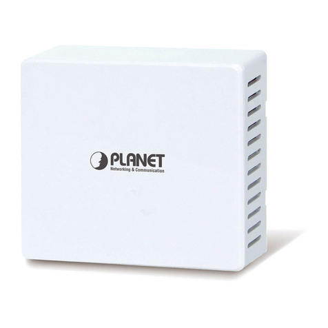
Netstar Niveo NWA200 User manual

i
MANUAL NWA200
Niveo Professional In-Wall 300N PoE Acces Point

ii
Copyright Statement
is the registered trademark of Netstar Products BV. All the products and
product names mentioned herein are the trademarks or registered trademarks of their
respective holders. Copyright of the whole product as integration, including its accessories
and software, belongs to Netstar Products BV. No part of this publication can be
reproduced, transmitted, transcribed, stored in a retrieval system, or translated into any
language in any form or by any means without the prior written permission of Netstar
Products BV.

iii
Disclaimer
Pictures, images and product specifications herein are for references only. To improve
internal design, operational function, and/or reliability, Netstar Products BV reserves the
right to make changes to the products described in this document without obligation to
notify any person or organization of such revisions or changes. Netstar Products BV does
not assume any liability that may occur due to the use or application of, the product or
circuit layout(s) described herein. Every effort has been made in the preparation of this
document to ensure accuracy of the contents, but all statements, information and
recommendations in this document do not constitute the warranty of any kind, express or
implied.

iv
About This User Guide
Please read this user guide before you start! This user guide instructs you to install and
configure the device.
This user guide uses the following formats to highlight special messages:
Icon
Description
Note
This format is used to highlight information of importance or
special interest. Ignoring this type of note may result in ineffective
configurations, loss of data or damage to device.
Tip
This format is used to highlight a procedure that will save time or
resources.
How to Use This Book
Chapter
Content
IProduct Overview
Describes product appearance and lists features.
ⅡInstall
Explains how to install hardware and connect cables.
ⅢLogin
Explains how to logs in to the web interface.
ⅣFeatures & Configurations
Introduces how to configure the device features.
ⅤAppendix
Explains how to configure PC TCP/IP settings, gives
specifications and lists default feature values and Safety
and Emission Statement

v
Table of Contents
ABOUT THIS USER GUIDE ..................................................................................................................IV
I PRODUCT OVERVIEW ................................................................................................................... - 1 -
1WHAT IT DOES................................................................................................................................... - 1-
2PACKAGE CONTENT ............................................................................................................................. - 1-
3LED................................................................................................................................................. - 2-
4BUTTON &INTERFACE ......................................................................................................................... - 2-
5LABEL............................................................................................................................................... - 3-
ⅡINSTALL ..................................................................................................................................... - 4 -
ⅢLOGIN........................................................................................................................................ - 6 -
1CONFIGURE PC TCP/IP SETTINGS.......................................................................................................... - 6-
2LOG IN TO DEVICE............................................................................................................................... - 6-
ⅣFEATURES & CONFIGURATIONS ................................................................................................. - 8 -
1STATUS ............................................................................................................................................. - 8-
1.1 System Status .........................................................................................................................- 8 -
1.2 Wireless Status .......................................................................................................................- 8 -
1.3 Traffic Statistics ......................................................................................................................- 9 -
1.4 Wireless Clients ......................................................................................................................- 9 -
2QUICK SET UP .................................................................................................................................. - 10 -
3LAN SETTINGS ................................................................................................................................. - 11 -
4DHCP SERVER ................................................................................................................................. - 12 -
4.1. DHCP Server.........................................................................................................................- 12 -
4.2 DHCP Client List ....................................................................................................................- 13 -
5WIRELESS SETTINGS .......................................................................................................................... - 13 -
5.1 Basic Settings........................................................................................................................- 14 -
5.2 Radio ....................................................................................................................................- 18 -

vi
5.3 Channel Scan ........................................................................................................................- 20 -
5.4 Advanced Settings ................................................................................................................- 20 -
5.5 Access Control ......................................................................................................................- 21 -
5.6 QVLAN ..................................................................................................................................- 22 -
6SNMP ........................................................................................................................................... - 23 -
7TOOLS ............................................................................................................................................ - 23 -
7.1 Maintenance ........................................................................................................................- 24 -
7.2 Time & Date..........................................................................................................................- 25 -
7.3 Logs ......................................................................................................................................- 26 -
7.4 Configuration........................................................................................................................- 27 -
7.5 User Name & Password ........................................................................................................- 29 -
7.6 Diagnostics ...........................................................................................................................- 30 -
7.7 Reboot ..................................................................................................................................- 30 -
7.8 LED........................................................................................................................................- 32 -
ⅤAPPENDIX................................................................................................................................. - 33 -
1CONFIGURE PC TCP/IP SETTINGS........................................................................................................ - 33 -
Windows XP................................................................................................................................- 33 -
Windows 7..................................................................................................................................- 36 -
2FACTORY DEFAULT SETTINGS &SPECIFICATIONS ...................................................................................... - 39 -
Default Settings ..........................................................................................................................- 39 -
3SAFETY AND EMISSION STATEMENT ...................................................................................................... - 41 -

- 1 -
I Product Overview
1 What It Does
The NWA200 is a best-in-class 802.11n indoor access point designed specifically for
business-class environments such as hotels, airports, coffee shops, shopping centers,
sporting venues, and university campus. With standard install design and stylish
appearance, it nicely fits into an 86-type wall jack and seamlessly blends in with most
interior decorations in an office or room. No need to rebuild or change existing walls. The
unit comes with a built-in USB port that charges mobile devices such as a smart phone via
a USB cable as well as a RJ11 port for connecting telephone. Integrated 802.3af Power
over Ethernet (PoE) allows installation in areas where power outlets are not readily
available. Client connected to the device’s LAN port can still communicate with the remote
uplink device (PoE switch) even when no power is supplied.
2 Package Content
Unpack the package. Your box should contain the following items:
1. AP
2. 2*Screws
3. Install Guide
4. Resource CD
If any of the parts are incorrect, missing, or damaged, contact your dealer. Keep the
carton, including the original packing materials, in case you need to return the product for
repair.

- 2 -
3 LED
LED
Color
Status
Description
PWR
Green
Solid
The device is connected to power supply.
Blinking
The device is functioning correctly.
Off
Power is not supplied to the device or the device is
malfunctioning.
4 Button & Interface
❶ReSeT: Open the housing of the AP and press this reset button for 7 seconds to
restore the device to the factory default settings.
❷RJ11 Phone Interface: For connection to a telephone.
❸USB Port: The USB port that charges terminal devices with a USB cable.

- 3 -
❹LAN: 100M Ethernet Port for connecting to an Ethernet LAN device such as a PC or
switch, etc. This port support “Bypass”. Client connected to the device’s LAN port can still
communicate with the remote uplink device (PoE switch) even when no power is supplied.
❺Green Connector: For connecting to a 4-core phone cable.
❻RJ45: The RJ45 port for connecting to a PoE switch.
5 Label
1. Default Login IP address: 192.168.2.200.This IP address is to be used to access the
router’s settings through a web browser. If you change it, you have to open a new
connection to the new IP address and log in again.
2. Administrator user name: admin
3. Password; admin

- 4 -
ⅡInstall
1. Remove the cover of the device.
2. Install and power the device (Connect one end of an Ethernet cable to the PoE switch
and the other end to the Ethernet port on the back panel of the device; connect the
phone cable to the green connector).
3. Connect terminal devices.

- 5 -
4. Make sure all connections are established correctly as seen in the diagram.

- 6 -
ⅢLogin
1 Configure PC TCP/IP Settings
Connect your PC to this device wirelessly or using an Ethernet cable. The default IP
address of your wireless access point is 192.168.2.200. If you are using the default IP
subnet, the computer you are using to connect to the device should be configured with an
IP address that starts with 192.168.2.x (where x can be any number between 2~253) and
a Subnet Mask of 255.255.255.0; if you have changed the subnet of the wireless access
point, the computer you are using to connect must be within the same subnet.
Tip
If you are not clear about how to set up your PC's IP address, see1 Configure PC TCP/IP
Settings.
2 Log in to Device
1. Launch a web browser, say, IE, input 192.168.2.200 and press Enter.
2. The login window appears. Enter the login user name and password (Both are
"admin" by default) and click Login.
Tip
You can click Tools -> User Name & Password to manage this user name and password.
For more information, see 6.5 User Name & Password.

- 7 -
3. You will now enter the web configuration interface as seen below.

- 8 -
ⅣFeatures & Configurations
1 Status
This section includes the following:
1.1 System Status: View the device’s system information and LAN settings.
1.2 Wireless Status:View the device’s wireless information and current SSID settings.
1.3 Traffic Statistics: View current traffic statistics of each SSID.
1.4 Wireless Clients:View the MAC addresses and connection speed of the wireless
clients that currently connect to each SSID.
1.1 System Status
Here you can view the device’s system status and LAN status.
1.2 Wireless Status
Click Status -> Wireless Status and you can view the device’s wireless information and
current SSID settings.

- 9 -
1.3 Traffic Statistics
Click Status -> Traffic Statistics and you can view current traffic statistics of the device's
SSID.
1.4 Wireless Clients
Click Status -> Wireless Clients and you can view the MAC addresses and connection
speed of the wireless clients that currently connect to each SSID.
To view wireless clients connected to a specific SSID, simply select it from the drop-down
list on the screen.

- 10 -
2 Quick Set up
Here you can quickly change the standard settings from default to customized values.
AP Mode: In this mode, this device can be connected to wireless clients, but cannot
connect other APs actively.
WDS Mode: In this mode, this device can provide access to at most 4 APs.
Universal Repeater Mode (AP Client Mode): In this mode, NWA200 negotiates with the
uplinkedAP successfully and also provides access to lower clients.

- 11 -
3 LAN Settings
Here you can configure the device's LAN IP address for Internet access. This IP address
is also to be used to access the device’s settings through a web browser. Most of the
default settings work in most cases. However, if your access point is part of a more
complex LAN network, then modify the settings to meet the requirements of your network
based on the explanation of the various fields.
Address Mode-Static IP: Manually specify the Static IP information (LAN IP address,
subnet mask, gateway, DNS server address) that corresponds with your existing
networking equipment.
Address Mode-Dynamic IP: Select it if you already have an active DHCP server on your
existing network. The wireless access point gets its IP address, subnet mask, and default
gateway settings automatically from the DHCP server on your network when you connect
the access point to your existing network.
Tip
1. Default IP address and subnet mask are respectively 192.168.2.200 and
255.255.255.0.
2. Be sure to make a note of any changes you apply to this page. If you change the LAN
IP address of this device, you have to update your PC’s TCP/IP settings and open a new
connection to the new IP address and then log in again.

- 12 -
4 DHCP Server
This section includes the following:
4.1. DHCP Server: Configure DHCP server settings.
4.2 DHCP Client List: View the information of the DHCP clients that currently obtain IP
addresses from the DHCP server.
4.1. DHCP Server
DHCP (Dynamic Host Configuration Protocol) assigns an IP address to each device on
the LAN/private network. When you enable the DHCP Server, the DHCP Server will
automatically allocate an unused IP address from the IP address pool specified in this
screen to the requesting device as long as the device is set to "Obtain an IP Address
Automatically". If you disable this feature, you have to manually configure the TCP/IP
settings for all PCs on your LAN to access Internet.
Click DHCP Server to enter the configuration screen.
To set up the DHCP Server:
1. Enable the DHCP Server.
2. Specify the starting and ending address of the IP address pool. These addresses
should be part of the same IP segment as the remote Internet enabled device's LAN
IPAddress.
3. Specify the lease time. It is a time length that the IP address is assigned to each
device before it is refreshed.
4. Specify the subnet mask. It should match the remote Internet enabled device's LAN

- 13 -
subnet.
5. Set the gateway address to the LAN IP address of the remote device.
6. Configure correct DNS settings. If a wrong DNS server address is entered, Web
pages may not be open.
Note
If there is already an active DHCP server on your network, make sure the IP address pool
you specified here is not a part of that existing DHCP server. Otherwise, IP collisions may
occur.
4.2 DHCP Client List
Click DHCP Server -> DHCP Client List to enter the DHCP clients screen. Here you can
view the host name, IP address, MAC address, and lease time information.
5 Wireless Settings
This section describes the following.
5.1 Basic Settings:Here you can configure the basic wireless settings of the device such
as the SSID (name of the network) and broadcast SSID, etc.
5.2 Radio: Here you can configure basic wireless settings including network mode and
channel, etc.
5.3 Channel Scan: Here you can scan current wireless signals.
5.4 Advanced Settings:Here you can configure advanced wireless settings. This is only
recommended to advanced users.

- 14 -
5.5 Access Control: Specify a list of devices to allow or disallow a connection to your
wireless network via the device's MAC addresses.
5.6 QVLAN:Here you can configure the QVLAN feature to better manage wireless traffic
and enhance wireless security.
5.1 Basic Settings
Here you can configure the basic wireless settings of the device such as the SSID (name
of the network) and security.
SSID: Select the SSID you wish to use. This is the public name of your wireless network.
Two SSIDs are supported.
Enable: Select whether to enable the selected SSID.
Broadcast SSID: This option allows you to have your network names (SSIDs) publicly
broadcast or if you choose to disable it, the SSIDs will be hidden. To join your hidden
wireless network, you must enter the SSID manually.
AP Isolation: Isolates clients connecting to this SSID.
Maximum Clients: Set the number of wireless clients that can join your wireless network.
When the number of wireless clients reaches the set value, new connections to this SSID
will be denied.
SSID: This field is configurable. You can change the current SSID.
Security Mode: Configure security settings for the current SSID. This device supports
WEP, WPA-PSK, WPA2-PSK, WPA/WPA2-PSK Mixed, WPA and WPA2 (To learn more,
read the following).
Table of contents
Popular Wireless Access Point manuals by other brands
Moxa Technologies
Moxa Technologies AWK-4121 Quick installation guide
Belkin
Belkin F5D7130 - Wireless G Access Point Declaration of conformity
Ruijie
Ruijie Reyee RG-RAP2260(G) Hardware installation and reference guide
Avaya
Avaya AP-3 user guide
3Com
3Com 3CRWE91096A - Wireless LAN Building-to-Building... datasheet
Proxim
Proxim Harmony 802.11a Network Adapter 802.11a user guide
TP-Link
TP-Link Pharos CPE210 installation guide
D-Link
D-Link DWL-3200AP - AirPremier - Wireless Access... product manual

D-Link
D-Link DWL-2100AP - AirPlus Xtreme G install guide
Alcatel-Lucent
Alcatel-Lucent OAW-RAP155 installation guide
Kaba
Kaba 90 04 Technical manual
Fortinet
Fortinet FortiAP 221E quick start guide
