manuals.online logo
Brands
  1. Home
  2. •
  3. Brands
  4. •
  5. NetZero
  6. •
  7. Indoor Fireplace
  8. •
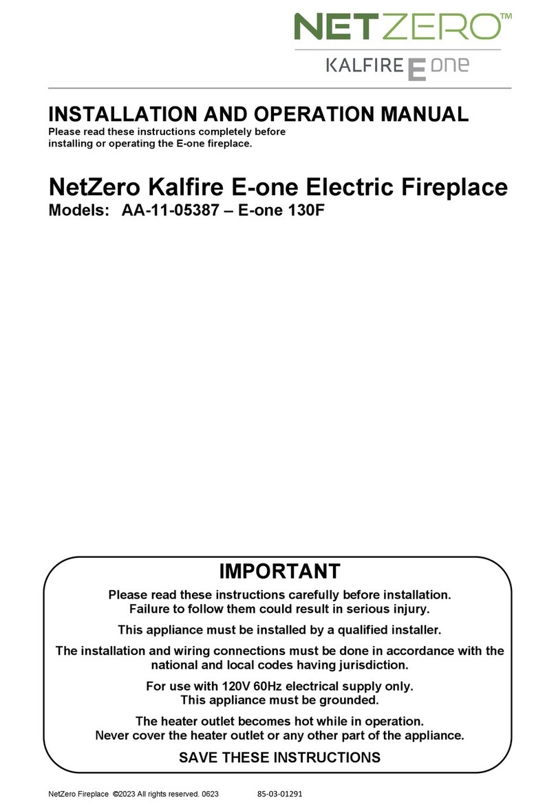
  9. NetZero Kalfire E-one AA-11-05387-E-one 130F User manual

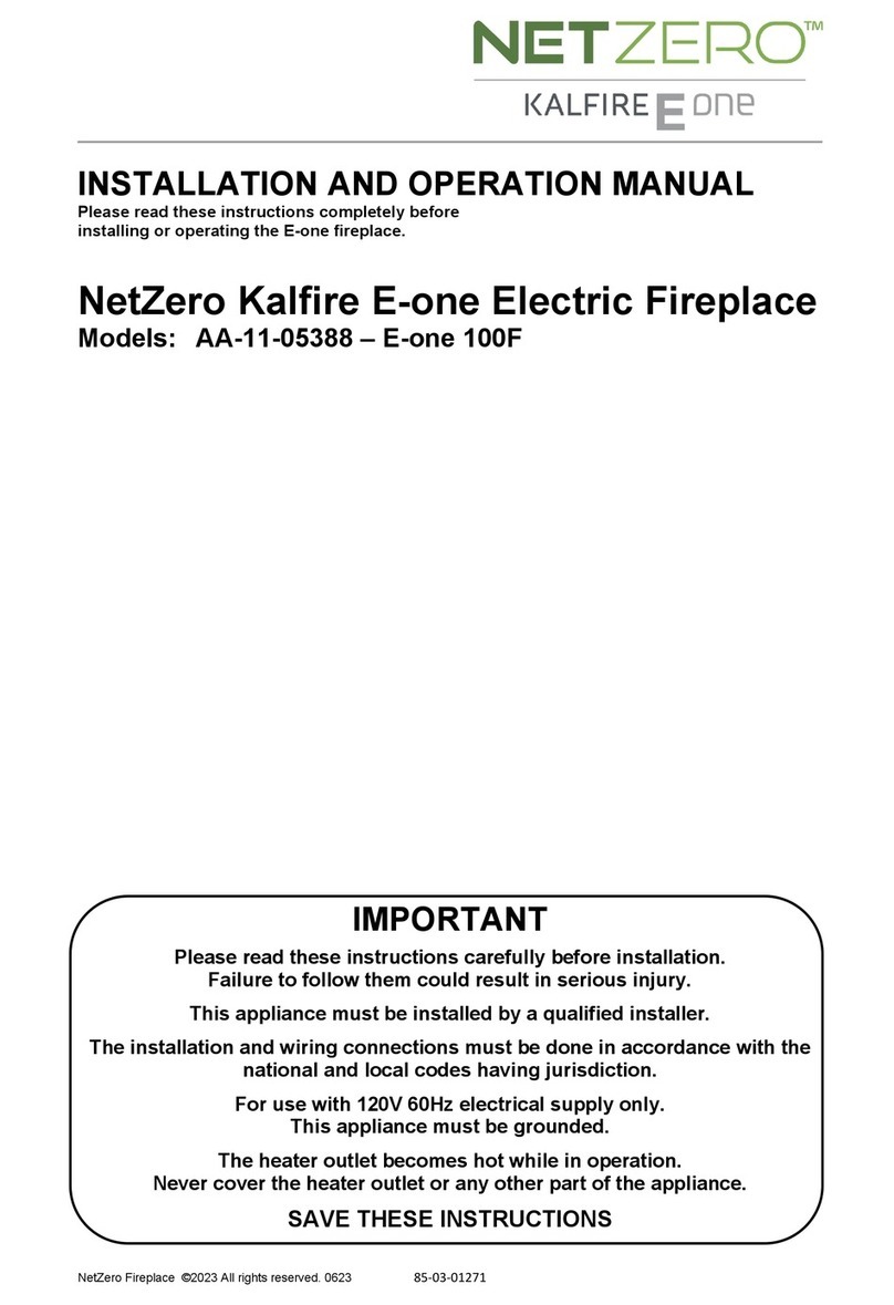
NetZero Kalfire E-one AA-11-05387-E-one 130F User manual

NetZero Fireplace ©2023 All rights reserved. 0623 85-03-01291
INSTALLATION AND OPERATION MANUAL
Please read these instructions completely before
installing or operating the E-one fireplace.
NetZero Kalfire E-one Electric Fireplace
Models: AA-11-05387 – E-one 130F
IMPORTANT
Please read these instructions carefully before installation.
Failure to follow them could result in serious injury.
This appliance must be installed by a qualified installer.
The installation and wiring connections must be done in accordance with the
national and local codes having jurisdiction.
For use with 120V 60Hz electrical supply only.
This appliance must be grounded.
The heater outlet becomes hot while in operation.
Never cover the heater outlet or any other part of the appliance.
SAVE THESE INSTRUCTIONS
2
Table of contents
1INTRODUCTION 3
1.1 Receiving Inspection 3
1.2 Certification 3
2GENERAL SAFETY REGULATIONS 3
2.1 Additional General Safety Regulations for
Atmos Heating 4
2.2 Disposal 4
2.3 California Proposition 65 Warning 4
3ASSEMBLY OF THE FIREPLACE 5
3.1 Required Tools 5
3.2 Included Hardware 5
3.3 Removal of Covers 5
3.4 Adjustable Feet 5
3.5 Rear Screen Assembly 5
3.6 Top Screen Assembly 7
4INSTALLING THE FIREPLACE 8
4.1 Light / Illumination 8
4.2 Viewing Height 8
4.3 Connecting Fireplace to Power 8
4.4 Ventilation Openings 8
4.5 Framing Dimensions 8
4.6 Wall Dimensions 9
4.7 Fireplace Finishing in Combination With
Atmos Heating 9
5SETTING UP THE FIREPLACE 10
5.1 Flat Bottom Plate 10
5.2 (Optional) Placing Design Bottom Plates 10
5.3 Placing Lower Sidewalls 10
5.4 Log Set Installation 11
5.5 Placing Glass Reflector 13
5.6 Placing Upper Side Walls 13
5.7 Placing Front Window 13
6E-ONE OPERATION 14
6.1 Main On/Off Switch 14
6.2 Hotel Switch 14
6.3 Remote Control Pairing 14
6.4 E-One Remote and Symbols 15
7MAINTENANCE 16
7.1 Cleaning The Fireplace 16
7.2 Cleaning The Glass Reflector 16
8WARRANTY 17
9TECHNICAL DATA 17
9.1 Specifications 17
9.2 Serial Number Label 17
9.3 Wire Diagram 18
9.4 Dimension Drawing 19
3
1INTRODUCTION
NetZero Fire stands for innovation and quality. This is why
we work continuously on the further development of our
products. We reserve the right to make changes to the
form, technology, and design of the products we sell. No
claims can be made on the basis of information and figures
from this manual.
This manual is protected by copyright. All rights are
reserved, particularly the right to copy, translate, and
process.
The fireplace may only be installed by a qualified installer, in
accordance with national or local regulations. Please read
this installation manual carefully.
1.1 Receiving Inspection
On receipt, check the following:
1) Verify that the packaging is not damaged
2) Check the glass panels and display screens of the
product for cracks.
3) Check that you have received the following parts:
•Fireplace: E-one
•Log and media set
•Top screen
•Rear screen (placed inside E-one)
•Glass reflector
•Front window
•E-one remote control
•Installation and operating instructions
•Design bottom plates (option)
•Side walls (4x)
•Adjustable feet (incl. nut) (4x)
•Rear screen mask
•Rear screen bracket
•Top LED rear screen bracket
•Fasteners
Note: Before installing the rear screen, top screen, and rear
screen mask remove the protective film.
1.2 Certification
This product has been certified by:
Intertek
545 E Algonquin Rd
Arlington Heights, IL 60005
This appliance has been certified to the American and
Canadian National Standards:
ANSI/UL 2021 – CAN/CSA C22.2 NO. 46
This device complies with Part 15 of the FCC Rules.
Operation is subject to the following two conditions:
(1) This device may not cause harmful interference, and
(2) This device must accept any interference received,
including interference that may cause undesired operation.
Note: This product has been tested and found to comply
with the limits for a Class B digital device, pursuant to Part
15 of the FCC Rules. These limits are designed to provide
reasonable protection against harmful interference in a
residential installation. This product generates, uses, and
can radiate radio frequency energy and, if not installed and
used in accordance with the instructions, may cause harmful
interference to radio communications. However, there is no
guarantee that interference will not occur in a particular
installation. If this product does cause harmful interference
to radio or television reception, which can be determined by
turning the equipment off and on, the user is encouraged to
try to correct the interference by one or more of the
following measures:
•Reorient or relocate the receiving antenna.
•Increase the separation between the equipment and
receiver.
•Connect the equipment into an outlet on a circuit
different from that to which the receiver is connected.
•Consult the dealer or an experienced radio/TV technician
for help.
Changes or modification not expressly approved by the
party responsible for compliance could void the user’s
authority to operate the equipment.
This device contains licence-exempt
transmitter(s)/receiver(s) that comply with Innovation,
Science and Economic Development Canada’s licence-
exempt RSS(s). Operation is subject to the following two
conditions:
1. This device may not cause interference.
2. This device must accept any interference, including
interference that may cause undesired operation of the
device.
Containes IC: 3147A-602230C
CAN ICES-003B / NMB-003B
NetZero Fire
1155 Sherman Road
Hiawatha, IA 52233
(800) 553-5422
2GENERAL SAFETY REGULATIONS
IMPORTANT INSTRUCTIONS
When using electrical appliances, necessary precautions
must always be taken to reduce and/or prevent the risk of
fire, electric shock, and personal injury:
•Read all instructions before installing or using this
heater.
•Follow the installation steps described in this
manual.
•Leave maintenance and repairs to a qualified
service provider: danger of electrocution!
•Caution: to reduce the risk of electric shock, do
not remove the ember bed.
•The unit contains no user-serviceable parts,
except cleaning of the glass reflector and front
window.
•If the unit is damaged, contact the supplier first.
•Do not use the fireplace outdoors.
•Do not burn wood or other materials in this
appliance.
•If the fireplace is switched on, the ambient
temperature of the room in which the fireplace is
placed must be between 40 and 85 degrees
Fahrenheit.
4
•Ambient temperature during storage and
transport should be between -5 and 140 degrees
Fahrenheit.
•Do not use the fireplace in the immediate vicinity
of a bath, shower, or swimming pool. The relative
humidity must be <85%.
•Do not place the fireplace directly under a wall
socket or junction box.
•If a malfunction occurs, set the main switch on
the front panel to 0 (OFF).
•Do not place the unit on carpet or rugs.
•To prevent overheating of the fireplace, it must
not be covered. Do not place any material in front
of or against the unit and, in particular, do not
obstruct the air circulation around the unit. When
materials overheat, there is a risk of fire.
•The fireplace may be operated by children aged
eight years and over and by people with reduced
physical, sensory, or mental abilities provided
they have demonstrated an understanding of the
instructions relating to the safe use and the
dangers of the fireplace. Children should not be
allowed to play with the fireplace or be involved
in any tasks pertaining to the maintenance of the
fireplace. Children are not allowed to play with
the fireplace. Children must not clean the
fireplace or perform user maintenance without
parental supervision.
•Children under the age of 3 should not be allowed
near the fireplace without adult supervision.
Children from three to seven years old may only
switch the fireplace on/off provided that it is
placed or installed in its intended normal working
position and that they have been given
explanation and instructions on how to use it
safely and understand the dangers. Children
three to seven years old must not clean the
fireplace or perform user maintenance.
•If the power lead becomes damaged,
it must be replaced by the supplier or another
qualified service provider to avoid danger.
2.1 Additional General Safety Regulations for
Atmos Heating
•The fireplace does not have an automatic
temperature regulator. If the fireplace is installed
in a small room, each person present in the room
must be able to leave the room independently.
Any person who is not, must be continuously
supervised.
•Some parts of the fireplace can become very hot
and could potentially cause burns. Always
maintain supervision of children and vulnerable
people around the fireplace.
•Do not insert or allow foreign objects to enter any
ventilation or exhaust opening as this may cause
an electric shock or fire or damage the heater.
•To prevent a possible fire, do not block air intakes
or exhaust in any manner.
•A heater has hot and arcing or sparking parts
inside. Do not use it in areas where gasoline,
paint, or flammable vapors or liquids are used or
stored.
•Use this heater only as described in this manual.
Any other use not recommended by the
manufacturer may cause fire, electric shock, or
injury to persons.
•Do not install electronics, artwork, or any other
item that can be damaged from heat rising from
the heater above the heater. NetZero Fire will not
be responsible for any damage to these items.
•Furniture, curtains, and other combustible
materials must be placed at least 3 feet (1 m)
away from the fireplace. Combustible materials
must not be placed within the dashed outlines
shown below.
SAVE THESE INSTRUCTIONS
2.2 Disposal
Recycle in accordance with Code of Federal Regulations
(CFR), Title 40, Part 273. This device is classified as electrical
and electronic equipment As such, it must not be disposed
of with household waste. At the end of its useful life please
take this product to an appropriate recycling center or
collection point. You can find your nearest recycling drop off
point by contacting your locality’s waste management
office.
2.3 California Proposition 65 Warning
WARNING: Cancer and Reproductive Harm –
www.P65Warnings.ca.gov.
5
3ASSEMBLY OF THE FIREPLACE
3.1 Required Tools
- 8mm Nut Driver or Socket
- 5mm Allen Wrench
- 3mm Allen Wrench
- 12mm Wrench
- 17mm Wrench
- Level
3.2 Included Hardware
- 4 X Adjustable feet
- 4 X (M6 x 8) Screws
- 2 X (M5 x 10) Screws
Do not use tie wraps to re-fasten cables during
installation.
While assembling the fireplace, place the
fireplace on a piece of cardboard or rug to
protect the floor from damage from metal parts.
3.3 Removal of Covers
Remove the top and rear cover from the fireplace.
3.4 Adjustable Feet
Lift the fireplace straight up to install the adjustable feet. Do
not tip it on its back or sides.
Note: Before installing the feet place the fireplace on a
protected surface such as carboard or a rug.
3.5 Rear Screen Assembly
Install the rear screen bracket to the top LED rear screen
bracket. Use 2 (M5 x 10) screws.
Use 4 (M6x8) screws to attach the rear screen to the
bracket. Remove the protective film from the screen.
Remove the protective film from the rear screen mask. This
is the plexiglass sheet with two tabs at the top. The mask
will hang on the tabs at the top of the rear bracket. The tabs
are different sizes. Align the larger tab with the larger slot
on the mask and the smaller tab with the smaller slot on the
mask.
6
Install the rear screen assembly in the back of the fireplace.
The bracket fits into slots at the back of the fireplace and
will rotate forward into the spring clips at the top.
WARNING: When rotating the screen forward move slowly.
Be careful to not pinch or damage any cables. Be aware of
your fingers and avoid pinch points.
After rotating the screen forward ensure both sides are
locked into the spring clips. Make sure the rear screen mask
is still in position.
Connect the rear screen:
1. HDMI
2. Power
3. Top LED
7
3.6 Top Screen Assembly
Remove the protective film from the top screen before
installing it into the fireplace. The pegs at the front of the
screen rest on brackets as shown below. When installing be
aware of your fingers and avoid pinch points.
Connect the top screen:
1. HDMI
2. Power
3. Backlight
Replace the rear and top panels with 8 (M5 x 10) screws.
The fireplace in now ready to be installed into your wall.
8
4INSTALLING THE FIREPLACE
4.1 Light / Illumination
The E-one functions on the basis of hologram technology.
This involves the use of a glass reflector that is placed at an
angle in the fireplace. Depending on where the fireplace is
positioned in the room, in exceptional cases, lighting above
the fireplace can cause a transparent white reflection on the
glass reflector.
4.2 Viewing Height
The E-one is best viewed straight on which allows for
optimum viewing of the holographic flames. If the fireplace
is installed too low in a wall it may be difficult to view the
flames. If the fireplace is installed too high in a wall the top
screen will be visible and detract from the realism of the
fire.
4.3 Connecting Fireplace to Power
This fireplace must be hardwired to a 120V, 60Hz, 15Amp
electric supply. Install on a dedicated 15Amp (or higher)
breaker.
This appliance must be grounded.
Wiring procedures and connections shall be in accordance
with the national and local codes having jurisdiction.
The fireplace is supplied with a cord inside the junction box
at the front right of the fireplace. This must be hardwired to
house power. To access the junction box at the front right of
the fireplace remove the bottom plate by lifting it out of the
fireplace.
4.4 Ventilation Openings
The chase the fireplace is installed in must have sufficient
ventilation for the fireplace to function correctly. A
minimum of 15 ½ in2(100 cm2) of free area is required.
One way to accomplish the required ventilation is to cut a
hole in the chase and install a 10” x 4” return air grill.
4.5 Framing Dimensions
Recommended framing is shown below.
Minimum space requirement to fit the fireplace are:
Width – 51 ¾” Height – 34 ½” Depth – 18”
The ceiling of the enclosure must be at least 6” above the
top of the heater or 11 ½” above the top of the fireplace.
Warning: Do not frame in front of the
heater. Doing so will not allow the heater
to be removed for service.
Once the fireplace is in position and level, secure it to the
back of the enclosure using the adjustable brackets at the
rear of the fireplace.
9
4.6 Wall Dimensions
Finish the wall around the guides on the fireplace The
dimensions for the finished opening are shown below. The
guides on the fireplace extend ¾” from the face of the
fireplace. For the best finish use wall material that is ¾”
thick.
The distance from the feet of the fireplace to the bottom
guide can be adjusted between 4” and 5”.
Temperatures above the heat outlet on the fireplace can
reach temperatures up to 175°F. Materials used in this area
must be rated for these temperatures. NetZero Fire is not
responsible for damage to walls because of the use of
improper materials or installation.
4.7 Fireplace Finishing in Combination With
Atmos Heating
When placing finishing material around the guides of the
fireplace it is recommended that a minimum clearance of
about 1/16 in. (2 mm) is maintained between the guides
and the fireplace for heat transfer and expansion. The metal
will expand when heated by the heater. If the finishing
material is too tight to the guides this can result in heat
transfer and material stress that could crack or damage the
finishing material.
10
5SETTING UP THE FIREPLACE
Place the fireplace in its final position before continuing to
set up the fireplace.
Level the fireplace using the adjustable legs.
Once you have levelled the fireplace, it is strongly
recommended that you attach it to the wall using the wall
brackets for added stability and safety.
5.1 Flat Bottom Plate
The fireplace comes with a flat bottom plate. The bottom
plate can be removed by lifting it up and out of the
fireplace. Removing the bottom plate will allow easier
access to the junction box at the front of the fireplace
during installation. After the fireplace is wired reinstall the
bottom plate.
If the optional design bottom plates will be used the flat
bottom plate must be removed and replaced with the
design bottom plates.
5.2 (Optional) Placing Design Bottom Plates
Please note: If a flat bottom plate was chosen, this step can
be skipped.
The design bottom plates are made of fragile
material. Therefore, proceed with extreme
caution when installing the bottom plates.
Place the side plates into the fireplaces. Then place the
centre plate between the two side plates.
Fireplace with the design bottom plates installed.
5.3 Placing Lower Sidewalls
The lower sidewalls fit into the fireplace as shown below.
The sidewall will sit flat on the floor of the fireplace. The
front flange of the sidewall will sit behind the guide at the
front of the fireplace. A magnet on the side of the fireplace
will hold the sidewall in place.
Make sure that the back of the lower side walls
are parallel to the rear wall.
11
5.4 Log Set Installation
The logs are made of fragile material. Therefore, proceed with extreme caution when installing the logs.
NOTE: Log set instructions are shown with the flat bottom floor installed in the fireplace.
When installing the log set it is important that the logs are places exactly as shown in these instructions. If logs are not placed
correctly the projected flame will not line up with the logs. A letter is moulded on the bottom of each log to make identifying the
log easy.
Start the log set installation by placing the first three logs on in the fireplace as shown below. Logs “M” and “N” have cutouts in the
bottom of the logs to sit on the stands at the back of the fireplace. Place log “D” on the left side of the ember bed as shown.
12
Place the next three logs on the ember bed as shown.
Next place log “K” on the right side of the ember bed. Log “O” is placed so that it is resting on log “P”. The placement of logs “P”
and “O” is important as a flame will be projected on the log.
To finish the installation, sprinkle the vermiculite and lava stones over the ember bed. First place the lava stones between and
around the logs. Then sprinkle vermiculite over the entire ember bed as well as on the floor plate around the ember bed. If too
much vermiculite is placed on the ember bed the light of the ember bed will not be visible.
It is suggested that after the glass reflector is placed in the next installation step that the fireplace is turned on. This will allow the
flames to be visible. The “P” and “O” logs can then be adjusted if needed to line up with the flame.
13
5.5 Placing Glass Reflector
The glass reflector is susceptible to stains and fingerprints.
For this reason, always use the supplied gloves for
installation. To clean the glass reflector, follow the cleaning
instructions provided in the maintenance section of this
manual.
Remove the protective film from the glass reflector before
installing the reflector into the fireplace. Be carefull when
installing to not damage the glass.
The glass reflector installs into the fireplace with the
attached extrusion at the front with the notch in the
extrusion facing down. Slide the glass reflector into the
fireplace. The back of the glass will rest on a bracket at the
top of the fireplace. The extrusion at the front of the glass
will fit over the two studs protruding from the side of the
fireplace at the front.
5.6 Placing Upper Side Walls
Install the upper side walls in the fireplace.
Install the side walls by placing the bottom point against the
extrusion on the glass reflector. Then rotate the side wall
towards the wall and the magnet will hold it in place.
5.7 Placing Front Window
Loosen the screws to slide the retaining clips up. Do not
remove the screws.
14
Wear the included gloves to handle the front window. Place
the front window into the two holders at the front of the
fireplace. Then rotate the window up. Slide the loosened
clips up so that the window can be positioned against the
top of the fireplace. Then slide the clips down to hold the
window in place.
Tighten the screws on the clips so they are snug. Do not
overtighten the screws.
6E-ONE OPERATION
With the E-one you can create your own fire experience
through the various functions and/or options.
6.1 Main On/Off Switch
Power to the fireplace can be switched On/Off using the
On/Off switch (I/O) on the front. The button is located at
the top right, behind the hinged cover (see figure). Lift the
cover up to access the switch.
If the unit is disconnected from power, the unit will be reset
to the factory settings.
IMPORTANT: If you do not intend to use the unit for a long
period of time, we advise you to switch off the unit by
setting the power button on the unit to the 0 (Off) position.
6.2 Hotel Switch
The fireplace can be switched On/Off by means of an
external switch. If the two luster terminals are connected
together, the fireplace switches Off.
The terminals for connecting the switch are located at the
front of the fireplace under the floor.
6.3 Remote Control Pairing
When the fireplace is used for the first
time, the remote control will connect
to the fireplace automatically. If the
following symbol is projected on the
rear screen, the remote control must
be paired manually:
Pairing is done by pressing the two buttons as shown below:
Press the and buttons on the remote
control at same time. Release the buttons when a red LED
light flashes in the top-left corner of the remote control.
You will know when the remote control is paired with the E-
one successfully once the symbol is no longer visible.
15
6.4 E-One Remote and Symbols
Atmos Heating (ON/OFF switch)
The specially developed Atmos Heating element provides a
pleasant atmospheric warmth, contributing to the ultra-
realistic fire experience.
Flame Appearance
Create your own flame appearance by choosing between
three flame types and adjust the flame intensity as desired.
Adjustable Flame Height
The flame height is adjustable from positions 1 to 5. The 6th
position is the Flame Shuffle mode. In Flame Shuffle mode,
dynamic flames are created by shuffling through the flame
heights.
NOTE: This feature is not available when flame type “A” is
selected.
Atmos Lighting
Atmos Lighting projects true shadow effects on the logs,
enhancing the ultra-realistic fire experience. The intensity is
adjustable from level 0 to 5. The Dynamic Atmos Lighting
mode creates a dynamic flicker effect within the interior.
When the fireplace is in Anti-Reflect mode, the intensity of
the Atmos Lighting can be adjusted from 0 to level 5.
Ember Bed
The ember bed simulates the real glowing bed of a fire. The
intensity is adjustable from level 0 to 5. The Dynamic ember
bed mode creates a dynamic flicker effect at the bottom of
the logs.
Sound
Choose between the full-bodied crackling sound of pine
wood or the calmer and relaxing sound of beech wood. The
sound of burning wood in combination with lifelike sparks
enable a true sensory experience. The volume can be
adjusted from level 0 to 5.
Power Button
This button has three functions: On, Anti-Reflect, Off.
Switching the fireplace On
Briefly press the power button. It takes about 30 seconds
for the fireplace to fully start up.
Anti-Reflect Function
When the fireplace is on briefly press the power button to
turn the fireplace off with the anti-reflect mode activated.
In this standby mode, the fireplace will be attractively lit.
This provides a nice view of the logs, even when the fire is
not burning.
Switching the fireplace Off
Press and hold the power button for two seconds to shut
the fireplace completely off.
1. Atmos Lighting Dimmer
2. Flames Higher/Flame Shuffle
3. Sound Softer
4. Flame Intensity
5. Atmos Heating
6. Ember Bed Dimmer
7. Dynamic Ember Bed On/Off
8. Power On/Off/Anti-Reflect
9. Atmos Lighting Brighter
10. Dynamic Atmos Lighting On/Off
11. Sound Louder
12. Flames Lower
13. Adjustable Flame Type
14. Sound
15. Ember Bed Brighter
16
7MAINTENANCE
CAUTION: Before cleaning, make sure the power has been
turned off at the circuit breaker panel and that the heating
element of the heater is cool.
7.1 Cleaning The Fireplace
Use a microfiber cloth or other soft cloth to clean the black
powder-coated parts of the fireplace.
Never use any solvents or aggressive cleaning agents. The
use of sandpaper, steel wool or brushes and scouring pads
is strictly not recommended. This will leave scratches on the
coating.
7.2 Cleaning The Glass Reflector
The glass reflector that is placed at an angle in the fireplace
must be treated with care.
Instructions for cleaning the glass reflector:
•Only clean the glass with clean water: cleaning
products are not recommended.
•Just dust the window or dry it with a clean
microfiber cloth.
•Always dry the pane completely: water residue is
difficult to remove.
Do not clean the glass reflector with any cleaning products,
abrasives, cerium oxide, etc. Never use hard materials such
as steel wool, razor blades, etc.
To clean the glass reflector, remove the front window from
the fireplace. To do so, follow these steps:
Loosen the screws and slide the retaining clips up.
Lean the top of the glass down and carefully remove it from
the fireplace. The glass reflector can now be accessed and
cleaned.
Replace the front window and secure the retaining clips.
Tighten the screws so they are snug. Do not overtighten.
17
8WARRANTY
NetZero Fire extends this 2-year Warranty to the original
purchaser of this appliance provided the product remains in
the original place of installation. The policy is not
transferable, amendable, or negotiable under any
circumstances.
Warranty protects against defect in manufacture or NetZero
Fire factory assembled components only, unless herein
specified otherwise.
It remains the full responsibility of the owner to operate this
appliance within the guidelines provided in the Installation
and Operating Instructions Manual accompanying this
appliance.
Any part(s) found to be defective during the warranty
period as outlined above will be repaired or replaced at
NetZero Fire’s option through an accredited distributor,
dealer or pre-approved and assigned agent provided that
the defective part is returned to the distributor, dealer or
agent for inspection if requested by NetZero Fire.
The authorized selling dealer, or an alternative authorized
NetZero Fire dealer if pre-approved by NetZero Fire, is
responsible for all infield diagnosis and service work related
to all warranty claims. NetZero Fire is not responsible for
results or costs of workmanship of unauthorized NetZero
Fire dealers or agents in the negligence of their service
work.
At all times NetZero Fire reserves the right to inspect
reported complaints on location in the field claimed to be
defective prior to processing or authorizing of any claim.
Failure to allow this upon request will void the warranty.
All warranty claims must be submitted by the dealer
servicing the claim, including a copy of the Bill of Sale (proof
of purchase by you). All claims must be complete and
provide full details as requested by NetZero Fire to receive
consideration for evaluation. Incomplete claims may be
rejected.
Unit must be installed according to all manufacturers’
instructions as per the manual by a NetZero Fire authorized
dealer, an authorized dealer technician or an authorized
service person only. All Local and National required codes
must be met. The installer is responsible to ensure the unit
is operating as designed at the time of installation.
Repair/replacement parts purchased by the consumer from
NetZero Fire after the original coverage has expired on the
unit will carry a 90-day warranty, valid with a receipt only.
Any item shown to be defective will be repaired or replaced
at our discretion. No labor coverage is included with these
parts.
Freight damages for products or parts are not covered
under the terms of the warranty.
9TECHNICAL DATA
9.1 Specifications
NetZero Kalfire E-one
Model: E-one 130F
Input: 120V – 60Hz – 12.3Amp
Power: 1,575 Watt
Heater output: 5,220 Btu/hr
Energy consumption per operating mode
standby mode (W)
9.2
standby mode, incl. anti-reflect function (W)
12
full operating mode, excl. Atmos Heating (W)
70.2
full operating mode, incl. Atmos Heating (W)
1,575
This fireplace must be hardwired to a 120V 15Amp electric
supply. Wiring procedures and connections shall be in
accordance with the national and local codes having
jurisdiction.
9.2 Serial Number Label
The serial number for the fireplace can be found inside the
fireplace on the left-hand side. To view the serial number
label, remove the front glass from the fireplace. Then
remove the panel that is magnetized to the left side of the
fireplace.
SAMPLE
18
9.3 Wire Diagram
19
9.4 Dimension Drawing
For framing the fireplace follow the framing dimensions and instructions given in this manual.
Warning: The ceiling of the enclosure must be at least 6” above the top of the heater or 11 ½” above the top of
the fireplace. Do not frame in front of the heater. Doing so will not allow the heater to be removed for service.
20
NETZEROFIRE.COM
1155 Sherman Rd, Hiawatha, IA 52233
(800)553-5422
NetZero is a distributor of these products, which are designed and manufactured by Kalfire B.V.
THERE ARE NO WARRANTIES WHICH EXTEND BEYOND THE DESCRIPTION ON THE FACE HEREOF AND SUPPLIED
MANUALS. IMPLIED WARRANTIES OF MERCHANTABILITY, IMPLIED WARRANTIES OF FITNESS, IMPLIED
WARRANTIES OF WORKMANSHIP AND OTHER IMPLIED WARRANTIES ARE EXCLUDED BY NETZERO.

Other NetZero Indoor Fireplace manuals

NetZero Kalfire E-one 130B User manual

NetZero

NetZero Kalfire E-one 130B User manual

NetZero E-one 100 User manual

NetZero

NetZero E-one 100 User manual

NetZero Waterplace Series User manual

NetZero

NetZero Waterplace Series User manual

NetZero Firebox Series User manual

NetZero

NetZero Firebox Series User manual

NetZero Kalfire E-one 130F User manual

NetZero

NetZero Kalfire E-one 130F User manual

NetZero Kalfire E-one AA-11-05388 - E-one 100F User manual

NetZero

NetZero Kalfire E-one AA-11-05388 - E-one 100F User manual

NetZero Kalfire E-one AA-11-05386-E-one 130B User manual

NetZero

NetZero Kalfire E-one AA-11-05386-E-one 130B User manual

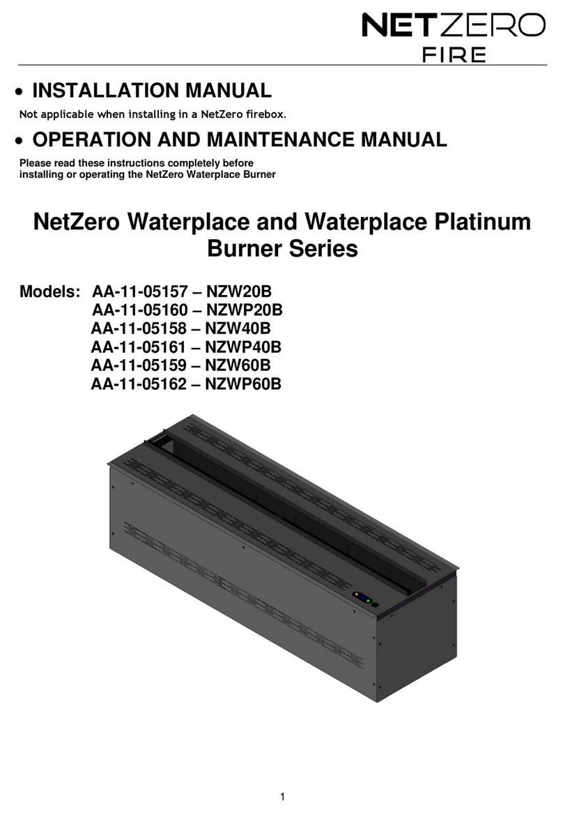
NetZero Burner Series User manual

NetZero

NetZero Burner Series User manual

NetZero Firebox Series User manual

NetZero

NetZero Firebox Series User manual

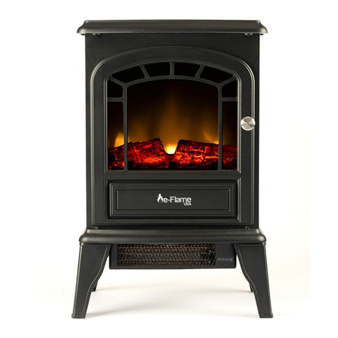
Popular Indoor Fireplace manuals by other brands

foc.us Eurofocus 951 pivotant Specific instructions

foc.us

foc.us Eurofocus 951 pivotant Specific instructions

Calflame FRP9092 owner's manual

Calflame

Calflame FRP9092 owner's manual

Pur Line bio chimenea F96180 installation instructions

Pur Line

Pur Line bio chimenea F96180 installation instructions

Boldflame TERES SP5543 user manual

Boldflame

Boldflame TERES SP5543 user manual

Stove Builder International XTD1.5-I owner's manual

Stove Builder International

Stove Builder International XTD1.5-I owner's manual

Heat & Glo Wood Burning Fireplace HST-42D owner's manual

Heat & Glo

Heat & Glo Wood Burning Fireplace HST-42D owner's manual

Vanguard WMH26TNB OWNER'S OPERATION AND INSTALLATION MANUAL

Vanguard

Vanguard WMH26TNB OWNER'S OPERATION AND INSTALLATION MANUAL

Calflame FPR 4000 owner's manual

Calflame

Calflame FPR 4000 owner's manual

RealFlame MAGIGLO 320 Installation & operating manual

RealFlame

RealFlame MAGIGLO 320 Installation & operating manual

Heat & Glo SOULSTICE-LP parts list

Heat & Glo

Heat & Glo SOULSTICE-LP parts list

Focal Point BLENHEIM Installation & user's instructions

Focal Point

Focal Point BLENHEIM Installation & user's instructions

Firesense BLT-999W-1 owner's manual

Firesense

Firesense BLT-999W-1 owner's manual

Heat & Glo RUTHERFORD 50-B owner's manual

Heat & Glo

Heat & Glo RUTHERFORD 50-B owner's manual

Vanguard VSGF-28NTE OWNER'S OPERATION AND INSTALLATION MANUAL

Vanguard

Vanguard VSGF-28NTE OWNER'S OPERATION AND INSTALLATION MANUAL

Heat & Glo LUX60 owner's manual

Heat & Glo

Heat & Glo LUX60 owner's manual

RealFlame 11511LP owner's manual

RealFlame

RealFlame 11511LP owner's manual

Classic Flame 36EB110-GRT user guide

Classic Flame

Classic Flame 36EB110-GRT user guide

Focal Point L23S MIDNIGHT Installation & user's instructions

Focal Point

Focal Point L23S MIDNIGHT Installation & user's instructions

manuals.online logo
manuals.online logoBrands
  • About & Mission
  • Contact us
  • Privacy Policy
  • Terms and Conditions

Copyright 2025 Manuals.Online. All Rights Reserved.