Neumann.Berlin DMI-2 User manual

· . · ·
() / · · @. · ..
DMI
B
M I
O I
D M I
2
D3D
1. Einleitung
In dieser Anleitung fi nden Sie alle wichtigen In-
formationen für den Betrieb und die Pfl ege des
von Ihnen erworbenen Produ tes. Lesen Sie diese
Anleitung bitte sorgfältig und vollständig, bevor
Sie das Gerät benutzen. Bewahren Sie die Anlei-
tung bitte so auf, dass sie für alle momentanen
und späteren Nutzer jederzeit zugänglich ist.
Weitergehende Informationen, insbesondere
auch zu den verfügbaren Zubehörteilen und den
Neumann-Servicepartnern, fi nden Sie auf unserer
Website www.neumann.com. Die Servicepartner
önnen Sie auch telefonisch unter +49 (0) 30 /
41 77 24 – 0 erfragen.
Auf unserer Website www.neumann.com fi nden
Sie in der Rubri Downloads ergänzend folgende
PDF-Dateien:
Bedienungsanleitung KM D – digitale Klein-
mi rophone
Bedienungsanleitung D-01 – digitales Groß-
membran-Mi rophon
Kurzbeschreibung des AES 42-Standards
Weitergehende Informationen zur Schnittstelle
digitaler Mi rophone fi nden Sie bei www.aes.org/
standards unter „AES standard for acoustics – Di-
gital interface for microphones“.
Zum weltweiten Erfahrungsaustausch unter
Neumann-Anwendern bieten wir das Neumann
Online-Forum an, das sich durch die integrierte
Archivfun tion zu einem umfangreichen Know-
How-Pool entwic elt hat.
2. Sicherheitshinweise
Der bestimmungsgemäße Gebrauch des Digitalen
Mi rophon-Interfaces DMI-2 ist die Speisung und
Fernsteuerung digitaler Mi rophone nach dem
internationalen Standard AES 42 und die Bereit-
stellung des Audiodatenstroms vom Mi rophon
für die Aufzeichnung oder Weiterverarbeitung im
AES/EBU-Format.
Schließen Sie an die Eingänge nur Mi rophone
an, die dem Standard AES 42 entsprechen.
Verbinden Sie die Ausgänge nur mit AES/EBU-
Eingängen.
Die RJ-45-Buchsen des DMI-2 tragen Gleich-
spannung und d rfen nicht an ein Ethernet
angeschlossen werden.
•
•
•
•
•
Reparatur- und Servicearbeiten d rfen nur
von erfahrenem und autorisiertem Fachper-
sonal durchgef hrt werden. Wenn Sie die
Geräte eigenmächtig öff nen oder umbauen,
erlischt die Gewährleistung.
Lassen Sie das Gerät auf Umgebungstempera-
tur a limatisieren, bevor Sie es einschalten.
Nehmen Sie das Gerät nicht in Betrieb, wenn es
beschädigt ist.
Verlegen Sie Kabel stets so, dass niemand dar-
über stolpern ann.
Halten Sie Flüssig eiten und ele trisch leitfä-
hige Gegenstände, die nicht betriebsbedingt
notwendig sind, von den Geräten und deren
Anschlüssen fern.
Verwenden Sie zum Reinigen eine Lösungs-
mittel oder aggressiven Reinigungsmittel.
Entsorgen Sie die Geräte nach den Bestimmun-
gen Ihres Landes.
Allgemeiner Hinweis: Alle zu Mi rophonen ge-
machten Angaben beziehen sich auf digitale Mi-
rophone der Solution-D-Serie von Neumann.
Haftungsausschluss:
Die Georg Neumann GmbH übernimmt einerlei
Haftung für einen Gebrauch des Produ ts, der
von den in der Bedienungsanleitung genannten
technischen Voraussetzungen abweicht (z.B. Be-
dienungsfehler, falsche Spannung, Abweichung
von empfohlenen Korrespondenzgeräten). Dies
gilt auch dann, wenn auf mögliche Schäden bei
abweichendem Gebrauch hingewiesen wurde.
Jegliche Geltendmachung von Schäden und Fol-
geschäden, die dem Benutzer aufgrund eines sol-
chen abweichenden Gebrauchs entstehen sollten,
wird ausgeschlossen. Ausgenommen von diesem
Haftungsausschluss sind Ansprüche aufgrund des
Produ thaftungsgesetzes.
3. Beschreibung
Das DMI-2 ist ein Speise- und Steuergerät für digi-
tale Mi rophone, die nach dem Standard AES 42
arbeiten (www.aes.org).
Die angeschlossenen Mi rophone werden mit
Strom versorgt und die empfangenen Audiosig-
nale im AES/EBU-Datenformat (AES 3) ausgege-
ben.
•
•
•
•
•
•
Das DMI-2 stellt die Kommuni ation zwischen di-
gitalen Mi rophonen und einem PC/Mac mit der
Neumann-Fernsteuerungssoftware RCS her und
generiert die dazu notwendigen Steuerdaten. Au-
ßerdem wird die Synchronisation der Mi rophone
mit einem externen oder dem intern erzeugten
Word Cloc durchgeführt.
Die wichtigsten Fun tionsmer male des DMI-2
sind:
Speisung von zwei digitalen Mi rophonen
(Standard AES 42).
Empfang des Audiodatenstroms vom Mi ro-
phon und Ausgabe als AES/EBU-Signal.
Synchronisation der Mi rophone mit einem ex-
ternen oder dem intern erzeugten Word Cloc
(automatische Er ennung).
Unterstützung aller üblichen Abtastraten:
44,1 / 48 / 88,2 / 96 / 176,4 / 192 Hz.
Unterstützung des asynchronen Betriebs. Da-
bei wird der Audiodatenstrom mit der aus dem
Mi rophonsignal rüc gewonnenen Abtastrate
am AES/EBU-Ausgang ausgegeben.
Computerschnittstelle zur Durchleitung und
Verarbeitung bidire tionaler Steuerdaten.
Neumann stellt für diesen Zwec eine Steuer-
software zur Verfügung, die auf PC und Mac
lauff ähig ist (Remote Control Software – RCS).
User Port zur dire ten Steuerung (Schalt on-
ta t bzw. A tiv-Low-Signal) ausgewählter
Fun tionen (Mute, LED1, LED2)
Mehrere Geräte önnen as adiert werden.
Interner Speicher: Alle Einstellungen bleiben
nach dem Ausschalten des DMI-2 erhalten.
Nach dem Wiedereinschalten werden diese
Einstellungen wir sam, auch ohne dass eine
Verbindung zum Computer besteht (Stand-
alone-Betrieb).
Anzeigen (Abb. 1)
Power
Anzeige der Betriebsbereitschaft. Während des
Startvorgangs leuchtet die Anzeige mit redu-
zierter Hellig eit.
Data Valid
Anzeige eines gültigen AES 42-Datenstroms vom
Mi rophon zum DMI-2.
•
•
•
•
•
•
•
•
•
Sync Locked
Anzeige der Synchronisation des Mi rophons mit
einem Master Word Cloc . Die Anzeige blin t,
während das Mi rophon synchronisiert wird. Sie
leuchtet durchgehend, wenn das Mi rophon er-
folgreich synchronisiert ist.
Ext Word Clk
Anzeige eines externen Word Cloc s. Die Anzei-
ge ist aus, wenn ein externes Word Cloc -Signal
er annt wird. Die Anzeige blin t, wenn ein Signal
am externen Word Cloc -Eingang anliegt, aber
(noch) eine Synchronisation erreicht ist. Die
Anzeige leuchtet durchgehend, wenn das DMI-2
erfolgreich mit dem externen Word Cloc syn-
chronisiert ist. Ein dauerhaftes Blin en der Anzei-
ge bedeutet, dass zwar ein Signal am Word Cloc -
Eingang anliegt, welches aber nicht als gültiges
Signal interpretiert wird. Ursache: eine gültige
Word Cloc -Frequenz (+/–50 ppm) oder sehr hohe
Jitter-Werte.
Anschl sse (Abb. 2)
Master Clock In/Out
In digitalen Studioeinrichtungen wird übli-
cherweise ein zentraler Master Word Cloc zur
Synchronisation der angeschlossenen Geräte
verwendet. Das DMI-2 synchronisiert sich auf
diesen externen Word Cloc automatisch, sobald
ein solches Signal am Word Cloc -Eingang (BNC
– 75 Ohm) er annt wird.
Liegt ein gültiger Word Cloc am Eingang an,
a tiviert das DMI-2 automatisch einen internen
Word Cloc -Generator. Die Word Cloc -Frequenz
entspricht der Abtastrate der synchron betrie-
benen Mi rophone (s. Kapitel „Synchronisation“).
Am Anschluss Master Cloc (Word Cloc ) Out
steht daher der empfangene externe bzw. der in-
tern generierte Word Cloc für andere Geräte zur
Verfügung.
Auch im stromlosen Zustand des DMI-2 wird
ein externer Word Cloc dire t zum Word Cloc
Out-Anschluss durchverbunden. Stec t auf der
Ausgangsbuchse des externen Word Cloc s ein
Kabel, wird eine automatische Terminierung
(75 Ohm) des Word Cloc -Eingangs wir sam.
Ab Hardware-Version 03:
Als externes Word Cloc -Signal ann auch ein
AES 11-Signal verwendet werden.
•
D
4
D5D
Auch bei externer Synchronisation bleibt der
interne Cloc Generator (VCXO) wir sam und
wird mittels einer PLL auf den externen Word
Cloc synchronisiert. Hierdurch wird eine sehr
eff e tive Jitter-Unterdrüc ung erreicht.
AES 42 In
3-poliger XLR-Eingang zum Anschluss eines digi-
talen Mi rophons.
AES/EBU Out
3-poliger XLR-Ausgang für das AES/EBU-Aus-
gangssignal. Zulässige maximale Kabellänge in
Abhängig eit von der gewählten Abtastrate s. Ka-
pitel „XLR-Kabel“.
Das AES/EBU-Signal enthält standardmäßig 2 Au-
dio anäle (Stereo lin s und rechts).
Bei synchronem Betrieb zweier Mono-Mi ro-
phone (s. Kapitel „Synchronisation“) werden die
Audiodaten folgendermaßen auf die Audio anäle
des AES/EBU-Ausgangssignals verteilt:
Channel 1 AES/EBU Out
lin s: Mi rophon 1
rechts: Mi rophon 2
Channel 2 AES/EBU Out
lin s: Mi rophon 2
rechts: ein Signal
In allen anderen Fällen gilt folgende Beschaltung:
Channel 1 AES/EBU Out
lin s: Mi rophon 1
rechts ein Signal
Channel 2 AES/EBU Out
lin s: Mi rophon 2
rechts ein Signal
Control Bus
RJ-45-Buchsen zum Anschluss eines Steuerge-
räts, im allgemeinen eines Computers (PC/Mac).
Als Anschluss abel werden übliche Ethernet-
(Patch-)Kabel verwendet (Shielded Twisted Pair
– STP oder Unshielded Twisted Pair – UTP).
Die Datenübertragung entspricht einer RS 485-
Schnittstelle mit zusätzlichem Power-Anschluss
zur optionalen Versorgung eines externen Steuer-
geräts.
Achtung: Die RJ-45-Buchsen des DMI-2 dürfen
nicht an ein Ethernet angeschlossen werden.
Die beiden RJ-45-Buchsen sind parallel verbun-
den, um mehrere DMI-Geräte as adieren und
von einem Rechner bedienen zu önnen.
•
•
•
•
•
Der Anschluss an einen PC oder Mac wird über
deren USB-Port realisiert. Hierzu ist ein USB/RS
485-Converter im Lieferumfang enthalten. Auf
diese Weise wird die Plug&Play-Fähig eit vor-
handener USB-Anschlüsse mit der weitaus grö-
ßeren möglichen Kabellänge (mind. 100 m) einer
RS 485-Verbindung genutzt.
ID [Geräteadresse]
Kodierschalter auf der Geräterüc seite zur Ein-
stellung der Geräteadresse. Werden mehrere
DMI-Geräte as adiert und gemeinsam gesteuert,
müssen diese unterschiedliche Geräteadressen
(ID) aufweisen. Welche Adressen benutzt werden
dürfen, ist von der verwendeten RCS-Steuerungs-
software abhängig. Zur Zeit sind nur die Adressen
0 … 3 erlaubt. Siehe auch Abschnitt 5, Inbetrieb-
nahme.
Achtung: Die Änderung der Geräteadresse soll im
stromlosen Zustand des DMI durchgeführt wer-
den, da die neue Adresse nur beim Einschalten
des Geräts übernommen wird.
Zur Fun tionsweise und Zuordnung der Geräte-
adressen s. Bedienungsanleitung der Steuerungs-
software RCS.
Achtung: Auf der Gerätefrontseite befi ndet sich
eine mit „ID“ ge ennzeichnete Öff nung. Dahinter
befi ndet sich ein Druc taster für diverse ünftige
Fun tionen. Diese werden u.a. auch eine omfor-
table Geräteadressierung beinhalten. Zur Zeit ist
dieser Taster noch ohne Fun tion.
User Port
Dire te Steuerung von Mi rophonfun tionen
durch externe Schalt onta te oder Logi -Signale.
Die 9 Pins sind wie folgt belegt (low-a tiv):
Pin 1 Kanal 1 „Light 2“ aus (rote LED, z.Zt. nur im
Solution-D-Mi rophon D-01)
Pin 2 Kanal 1 „Light 1“ aus (blaue LED in Soluti-
on-D-Mi rophonen)
Pin 3 Kanal 1 Mute eingeschaltet
Pin 4 reserved
Pin 5 Ground
Pin 6 Kanal 2 „Light 2“ aus (rote LED, z.Zt. nur im
Solution-D-Mi rophon D-01)
Pin 7 Kanal 2 „Light 1“ aus (blaue LED in
Solution-D-Mi rophonen)
Pin 8 Kanal 2 Mute eingeschaltet
Pin 9 reserved
Die Pins önnen wahlweise durch Verbinden nach
Ground oder durch Logi -Ausgänge angesteuert
werden (TTL-Logi -Pegel). Zum Beispiel önnen
für eine Stummschaltung mit einem einzigen Kon-
ta t Mute a tiviert und die rote LED ausgeschaltet
werden (z.B. für „On Air“-Fun tion).
Achtung: Die jeweilige Schaltfun tion ist nur
dann a tiviert, wenn in der Steuerungssoftware
(RCS) der User Port für die Kontrolle der jewei-
ligen Fun tion ausgewählt wurde.
4. Lieferumfang
Digitales Mi rophon Interface DMI-2
USB 485-Konverter
USB-Kabel
RJ-45-Kabel
Netz abel
Bedienungsanleitung
CD mit RCS-Software und USB-Treibern
5. Inbetriebnahme
Die folgenden Schritte erläutern die erstmalige
Installation eines digitalen Mi rophonsystems,
bestehend aus Mi rophon, Digitalem Mi rophon-
Interface DMI-2 und Steuerungssoftware RCS.
Installieren Sie zuerst die Steuersoftware RCS
und die zugehörigen Treiber auf Ihrem Computer.
Für den Betrieb der Steuersoftware RCS beste-
hen an den Computer folgende Mindestanforde-
rungen:
Computer mit Windows 98 SE, ME, 2000, XP
oder Mac OS mit PPC (ab Version 8.6 und Car-
bonLib ab Version 1.6),
ein freier USB-Anschluss,
10 MB freier Festplattenspeicher,
Grafi aufl ösung 1024 x 768 oder mehr,
HiColor oder TrueColor,
CD-ROM-Laufwer ,
Maus und Tastatur,
Adobe Acrobat Reader (nur für Online Manual)
Starten Sie die SETUP-Routine auf der beige-
fügten CD-ROM (Windows: „Setup“, Mac OS: „In-
stall RCS“) und folgen Sie den Anweisungen auf
dem Bildschirm.
•
•
•
•
•
•
•
•
•
•
•
•
•
•
•
Achtung:
Für die Installation unter Windows 2000/XP
bzw. Mac OS X sind Administratorrechte erfor-
derlich.
Der Konverter USB 485 darf erst mit einem
USB-Port des Computers verbunden werden,
nachdem die RCS installiert wurde.
USB-Treiberinstallation
Nachdem die RCS installiert wurde, muss der
Schnittstellen onverter USB 485 mit einem USB-
Anschluss des Computers verbunden werden.
Auf diese Weise ist sichergestellt, dass der mit-
gelieferte USB-Treiber, der für den Betrieb des
Konverters erforderlich ist, geladen wird. Falls
unter Windows nach dem Speicherort der Treiber-
dateien gefragt wird, ist das CD-ROM-Laufwer
auszuwählen. Vor dem Bestätigen muss sicherge-
stellt sein, dass sich die Installations-CD-ROM im
Laufwer befi ndet.
Weitere Verbindungen
Verbinden Sie den USB 485-Konverter über Patch-
Kabel mit einer der RJ-45-Buchsen (Control Bus)
des DMI-2.
Wählen Sie die Geräteadresse (ID) am DMI-2
(Kodierschalter an der Rüc seite des DMI). Die
Adressvergabe sollte bei „0“ beginnen. Es werden
zur Zeit die Adressen 0 ... 3 von der RCS unter-
stützt.
Achtung: Er ennung der ID nur während des
Einschaltvorgangs des DMI-2; daher nach Ände-
rung der ID Stromversorgung urz unterbrechen.
(s. Abschnitt „ID“, Seite 4)
Stellen Sie die Verbindung zwischen Mi rophon,
DMI-2 und dem nachfolgenden Gerät (z.B. Misch-
pult) über XLR-Kabel (s. „Kabel“) her.
Soll das DMI und die angeschlossenen Mi ro-
phone mit einem externen Master Word Cloc
synchronisiert werden, so verbinden Sie diesen
über ein BNC-Kabel mit dem Word Cloc Eingang
des DMI-2.
Bei Verwendung mehrerer DMIs önnen diese
über den Steuerbus as adiert werden. Dazu wird
ein RJ-45-Patch abel in die zweite RJ-45-Buchse
des DMI gestec t und mit einer der RJ-45-Buchsen
des zweiten DMI verbunden usw. Gegebenenfalls
leiten Sie auch den Word Cloc über die BNC-Aus-
gangsbuchse an weitere DMIs weiter.
Schließen Sie das DMI-2 an das Stromnetz an.
•
•
6
D7D
Starten Sie die RCS – gegebenenfalls erneut, falls
das Programm noch geöff net war.
Achtung: Das DMI-2 muss immer eingeschaltet
sein, bevor die RCS gestartet wird, damit das
DMI-2 vom PC/Mac er annt wird. Solange die RCS
arbeitet, darf das Verbindungs abel zwischen
Computer und USB 485-Konverter nicht abgezo-
gen werden, um ein un ontrolliertes Verhalten
des Computers zu vermeiden. Dies ergibt sich aus
der Spezifi ation der USB-Schnittstelle.
Lange Modulations abel und mehrfache Stec -
verbindungen führen zu einem Spannungsabfall
der Mi rophonspeisespannung und zu einer Ver-
schlechterung des Jitter-Verhaltens insbesondere
bei hohen Abstastraten. Verwenden Sie daher
möglichst durchgehende Kabelverbindungen
zwischen Mi rophon und DMI-2 bzw. DMI-2 und
dem Folgegerät und bei größeren Distanzen aus-
schließlich AES/EBU-Kabel (Wellenwiderstand
110 Ohm).
Achten Sie darauf, dass das Mi rophon und alle
Geräte der digitalen Signal ette synchronisiert
sind. Am Digitalen Mi rophon-Interface von Neu-
mann angeschlossene Mi rophone sollten immer
im Synchronmodus betrieben werden, unabhän-
gig davon, ob in der nachfolgenden Signal ette
Sample-Rate-Converter im Einsatz sind. Auf diese
Weise wird im DMI eine sehr eff e tive Jitter-Un-
terdrüc ung wir sam (ab Hardware-Version 03).
Auch ist die Ausgabe zweier Mi rophonsignale in
einem AES 3-Stereosignal nur möglich, wenn die
Mi rophone untereinander synchron laufen.
Achten Sie beim Anschließen von Kabeln auf die
orre te Verriegelung der Stec verbinder.
Verlegen Sie die Kabel so, dass sie eine Stolper-
gefahr darstellen.
Software-Update
Die Software im DMI-2 und in Neumann-Mi ro-
phonen ist update-fähig. Zu ünftige Updates
önnen ohne Öff nen des Geräts über die Steue-
rungssoftware RCS durchgeführt werden (s. Be-
dienungsanleitung RCS).
6. Außerbetriebnahme
Verringern Sie vor dem Abschalten von Mi ropho-
nen und Abziehen von Kabeln den Lautstär epe-
gel Ihres weiterverarbeitenden Gerätes.
Ziehen Sie beim Lösen von Kabeln stets nur an
den Stec verbindern und nicht am Kabel.
7. Technische Daten
Zulässige limatische Verhältnisse:1)
Betriebstemperaturbereich ...............0 °C … +45 °C
Lagerungstemperaturbereich ...... –20 °C … +70 °C
Feuchtebereich ....................... max. 90 % rel. hum.
bei +20 °C
Eingänge ...........................2x XLR 3 F nach AES 42,
Audiodaten entsprechend
AES/EBU- (AES 3-) Datenformat,
Phantomspeisung (DPP),
Fernsteuerdaten
Phantomspeisung
(DPP) ..................... +10 V, max. 250 mA pro Kanal,
urzschlussfest
Fernsteuerdaten ........................... Pulse (+2 V), der
Phantomspeisung
überlagert, ca. 750 Bit/s
Ausgänge ............... 2x XLR 3 M, AES/EBU- (AES 3-)
Datenformat
Unterstützte Abtastraten .......................44,1 / 48 /
88,2 / 96 Hz /
176,4 Hz*/ 192 Hz*
Synchronisation ...........................AES 42 – Mode 1
und Mode 2
Mode 1 ..................................Asynchroner Mode,
Mi rophon-Cloc freilaufend
auf gewählter Word Cloc -Frequenz –
bedingt Sample-Rate-Converter
(SRC) auf Empfängerseite
Mode 2 ................................... Synchroner Mode,
Ta tnachregelung durch PLL.
Bei fehlendem externen Word Cloc
wird automatisch der interne
Word Cloc -Generator a tiviert.
Word Cloc Input ..............................................BNC
Vin .......................................>250 mV an 75 Ohm
Word Cloc Output ............................................BNC
Vout ......................................... ca. 2 V an 75 Ohm
Interner Word Cloc -
Generator .......................44,1 / 48 / 88,2 / 96 Hz
176,4*/ 192 Hz2)
Genauig eit ................................................±25 ppm
Anzeigen ......................................................... Power
Data Valid (Mi rophon),
Sync Loc ed,
Ext Word Cloc
1) Alle Werte für nicht- ondensierende Feuchtig eit.
2) nur DMI-2 ab Hardware-Version 03
Control Bus ................................2x RJ-45-Buchsen,
Verbindung zum USB-Port
des Computers über
Neumann-Schnittstellen-
onverter USB 485,
für Kas adierungszwec e
parallel verbunden.
Datenformat: ...................RS 485 mit zusätzlichem
Power-Out-Pin (ca. +11,3 V)
Geräteadresse (ID) ...................................... 0 ... 15,
einstellbar mit
Kodierschalter
an der Geräterüc seite.
User Port ............................................. 9-pol Sub-D,
3 Schaltfun tionen pro Kanal
Stromversorgung ............... 90 ... 240 V, 50/60 Hz
Leistungsaufnahme .....................................< 30 VA
Abmessungen ..........(B x H x T) 218 x 56 x 163 mm
Gewicht .....................................................ca. 1,4 g
8. Zusatzerläuterungen
8.1 AES 42
Der Standard basiert auf der Verwendung 2-ad-
riger symmetrischer Kabel (AES/EBU-Kabel – bei
urzen Verbindungen auch her ömmliche Ana-
log abel). Die Stromversorgung digitaler Mi ro-
phone ist als Digital Phantom Power (DPP) von
+10 V, max. 250 mA defi niert. Durch Modulation
der Phantomspannung wird ein Fernsteuerdaten-
strom in Richtung Mi rophon erzeugt (+2 V-Pul-
se).
Das Datenformat des vom Mi rophon gesendeten
digitalen Audiosignals entspricht dem Standard
AES/EBU (AES 3). Die in diesem Standard defi -
nierten Userbits sind zur Übertragung diverser
Informationen vorgesehen. Im Standard AES 42
sind diese Userbits in ihrer Bedeutung für digi-
tale Mi rophone defi niert. Im DMI-2 werden diese
Daten vom Audiosignal getrennt und zum Control
Bus (Schnittstelle für Computer oder Steuergerät)
geleitet.
Abb. 3 zeigt ein einfaches Fun tionsdiagramm
eines Mi rophon-Interfaces mit AES 42-Eingang
und AES/EBU-Ausgang.
8.2 XLR-Kabel
Die realisierbare Leitungslänge von einem digi-
talen Neumann-Mi rophon zum DMI-2 hängt von
dem verwendeten Kabeltyp und von der gewähl-
ten Sampling-Rate (Word Cloc -Frequenz) ab. Bei
Längen bis zu 100 m bei 44,1/48 Hz-Abtastrate
önnen hochwertige „analoge“ XLR 3-Kabel (z.B.
IC 3 von Neumann) verwendet werden. Für größe-
re Leitungslängen wird die Verwendung von AES/
EBU-Kabeln (110 Ohm) erforderlich. Typischer-
weise önnen in diesem Fall Längen bis 300 m
(Abtastrate 44,1/48 Hz) bzw. 200 m (Abtastrate
88,2/96 Hz) bzw. 100 m (Abtastrate 176,4/192
Hz) realisiert werden.
Achtung: Bei längeren Verbindungen zwischen
Mi rophon und DMI-2 muss bei der Auswahl der
Kabel darauf geachtet werden, dass der DC-Wider-
stand einen maximalen Wert nicht überschreitet.
Dies ist nötig, um unzulässigen Spannungsabfall
der Phantomspeisung zu vermeiden. Es gilt fol-
gendes:
Ra/2 + Rs < 18 Ohm
Ra = DC-Widerstand der einzelnen Ader,
Rs = DC-Widerstand des Schirms bzw. der
GND-Rüc leitung.
Die realisierbare Leitungslänge vom DMI-2 zum
nachfolgenden Gerät (z.B. digitales Mischpult)
hängt maßgeblich von den technischen Eigen-
schaften des nachfolgenden Geräts ab. Hierzu
önnen eine spezifi schen Aussagen gemacht
werden. Im Zweifel ist die Verwendung von AES/
EBU-Kabeln (110 Ohm) empfehlenswert.
8.3 Betrieb ohne Steuerungssoftware RCS
Sämtliche Einstellungen, die beim Ausschalten
des DMI-2 wir sam sind, werden intern gespei-
chert und nach dem Wiedereinschalten automa-
tisch in das Mi rophon geladen. Die letzten Mi-
rophoneinstellungen werden wiederhergestellt,
ohne dass hierfür eine Verbindung zum Steuerge-
rät (PC/Mac) nötig ist.
Dies geschieht auch, wenn ein Mi rophon erst
später an das schon eingeschaltete DMI-2 ange-
schlossen wird.
Beim Starten der Steuerungssoftware RCS wird
die dort gespeicherte Konfi guration aller Mi-
rophon anäle mit den im DMI-2 gespeicherten
Einstellungen verglichen. Werden Unterschiede
er annt, wird in einem Auswahl-Menü abgefragt,
welche Konfi guration übernommen werden soll
(s. Bedienungsanleitung RCS).

8
D9D
8.4 Synchronisation
Der Standard AES 42 beschreibt zwei Arten der
Synchronisation des Mi rophons mit dem Emp-
fänger (z.B. Mischpult oder Digitales Mi rophon-
Interface – DMI-2):
Mode 1: Das Mi rophon arbeitet unsynchronisiert
mit der Abtastrate seines internen Quarzoszilla-
tors und benötigt auf der Empfängerseite einen
Abtastratenwandler (Sample-Rate-Converter).
Achtung: Dieser Modus sollte nur benutzt wer-
den, wenn Synchronisation nach Mode 2 nicht
möglich ist, da übliche Sample-Rate-Converter
die Signalqualität verschlechtern (Dynami um-
fang, Latenzzeit).
Mode 2: Das Mi rophon arbeitet synchron zu
einem Master Word Cloc . Dies ann ein exter-
ner oder der interne Word Cloc des DMI-2 sein.
Hierbei wird im AES 42-Empfänger (DMI-2) ein
Frequenz/Phasenvergleich mit dem Master Word
Cloc durchgeführt. Es wird ein Steuersignal er-
zeugt, das über den Fernsteuerdatenstrom zum
Mi rophon übertragen wird und dort die Frequenz
des internen Quarzoszillators steuert.
Der interne Word Cloc -Generator ann über die
BNC-Ausgangsbuchse zur Synchronisation wei-
terer DMIs und der weiterverarbeitenden Geräte
(z.B. Mischpult) verwendet werden.
9. Fehlercheckliste
Fehler
▶
Mögliche Ursachen
▶
Abhilfe
Ein am DMI angeschlossenes
und eingeschaltetes Mi rophon
wird an der RCS nicht angezeigt,
obwohl LED “DATA VALID“ am DMI
leuchtet.
DMI wird von der RCS Software
nicht er annt – Ursache:
Das DMI war beim Starten der RCS
noch nicht eingeschaltet.
RCS erst starten, nachdem das
DMI eingeschaltet wurde oder
Befehl Options/DMI ausführen und
Fenster wieder schliessen.
Eine derzeit von der RCS nicht
unterstützte ID oder Verwen-
dung derselben ID bei mehreren
Geräten.
Derzeitig wird nur eine ID im
Bereich 0 … 3 unterstützt. Einstel-
lung durch Kodierschalter auf der
Geräte-Rüc seite, für jedes Gerät
eine andere ID !
ID bei laufendem Betrieb geän-
dert.
DMI muss nach einer ID -Änderung
neu eingeschaltet werden, danach
RCS neu starten oder Befehl Op-
tions/DMI ausführen und Fenster
wieder schliessen.
Falsche Einstellung für Schnitt-
stelle (USB, COM1, COM2).
Richtige Schnittstelle in RCS über
Options/Communication wählen.
LED „Ext. Word Cl “ leuchtet
nicht, obwohl ein Ext. Word Cl
angeschlossen ist.
Es wird ein Word Cl – Signal
er annt.
Word Cloc Quelle und Kabelver-
bindung überprüfen.
LED „Ext. Word Cl “ blin t dau-
erhaft ( urzzeitiges Blin en nach
A tivierung eines Ext. Word Cl ist
normal und zeigt den Synchronisa-
tionsprozess an).
Word Cloc Signal liegt an, wird
aber nicht als gültiges Signal in-
terpretiert. Word Cloc Frequenz
weicht z.B. mehr als ± 50 ppm vom
Sollwert ab.
Word Cloc Frequenz überprüfen,
andere Quelle für Word Cloc
wählen. Alternativ Ext. Word
Cl entfernen und DMI als Word
Cl Master für die Signal ette
verwenden.
Fehler
▶
Mögliche Ursachen
▶
Abhilfe
LED „DATA VALID“ leuchtet nicht,
obwohl ein Mi rophon angeschlos-
sen und eingeschaltet ist (RCS-An-
zeige „AES42 PWR“ leuchtet).
Kein gültiger Datenstrom - Ur-
sache:
Kabelverbindung zum Mi rophon
mangelhaft oder zu lang
Kabelverbindung auf Unterbre-
chung prüfen.
Die für die gewählte Word Cl
Frequenz geltenden Grenzen
hinsichtlich max. Kabellängen
und erforderlicher Kabelqualität
beachten. Unnötige Übergangs-
stellen (Stec verbindungen) ver-
meiden. Siehe Kapitel 8.2, Kabel.
Mi rophon defe t. Anderes Mi rophon verwenden.
LED „SYNC LOCKED“ blin t dauer-
haft ( urzzeitiges Blin en während
des Sychronisationsvorgangs ist
normal).
Mi rophon wird nicht synchroni-
siert, weil die Word Cl - Frequenz
nicht unterstützt wird.
Eine Word Cl Frequenz auswäh-
len, die von allen angeschlossenen
Mi rophonen unterstützt wird.
LED „SYNC LOCKED“ leuchtet nicht. Mi rophon arbeitet im asynchro-
nen Modus (ist im Word Cl -Fens-
ter der RCS durch den Buchstaben
‚a‘ vor der Frequenzanzeige zu
er ennen).
Samplerate für Synchronmodus
bzw. „Sync to Ext. Word Cl “
einstellen.
Mi rophon unterstützt nur „Mode
1“ nach AES 42-Standard, d.h. es
ist nicht synchronisierbar.
Synchronisierbares Mi rophon
verwenden (alle Neumann-Mi ro-
phone der Solution-D-Serie).
Steuerung von Fun tionen über User
Port fun tioniert nicht.
User Port-Steuerung nicht freige-
geben.
Im Systemmenü der RCS Software
muss „Function controlled by
Userport“ für die gewünschte
Fun tion a tiviert sein.
10
US
GB 11
US
GB
1. Introduction
This manual contains essential information for the
operation and care of the product you have pur-
chased. Please read the instructions carefully and
completely before using the equipment. Please
eep this manual where it will be accessible at all
times to all current and future users.
Additional information, in particular concern-
ing available accessories and Neumann service
partners, can be found on our website: www.neu-
mann.com. Information about service partners
can also be obtained by telephone: +49 (0) 30 /
41 77 24 - 0.
The following related fi les are available in PDF
format in the Downloads section of our website
www.neumann.com:
KM D Operating Manual – Digital Miniature Mi-
crophones
D-01 Operating Manual – Digital Large-Dia-
phragm Microphone
Brief Description of the AES 42 Standard
Additional information concerning the digital mi-
crophone interface can be found at http://www.
aes.org/publications/standards/ under the title
“AES standard for acoustics – Digital interface for
microphones”.
The Neumann online forum enables Neumann
users worldwide to share their experiences.
Through its integrated archive function, the forum
has developed into an extensive nowledge pool.
2. Safety instructions
The DMI-2 Digital Microphone Interface has the
intended purpose of providing power and remote
control for digital microphones in accordance
with the international standard AES 42, and of
ma ing the audio data stream from the micro-
phone available in AES/EBU format for recording
or further processing.
Connect to the inputs only microphones that
comply with the AES 42 standard.
Connect the outputs only to AES/EBU inputs.
The RJ-45 ports of the DMI-2 have a DC
voltage, and must not be connected to an
Ethernet.
•
•
•
•
•
Repairs and servicing are to be carried
out only by experienced, authorized ser-
vice personnel. Unauthorized opening or
modifi cation of the equipment shall void
the warranty.
Allow the equipment to adjust to the ambient
temperature before switching it on.
Do not operate the equipment in a damaged
condition.
Always run cables in such a way that there is no
ris of tripping over them.
Ensure that liquids and electrically conductive
objects unless required for operation are ept
at a safe distance from the equipment and its
connections.
Do not use solvents or aggressive cleansers for
cleaning purposes.
Dispose of the equipment in accordance with
the regulations applicable to the respective
country.
Please note: All information relating to the micro-
phones refers to digital microphones of the Neu-
mann Solution-D series.
Disclaimer:
The product is sold “as-is” and the customer is as-
suming the entire ris as to the product’s suitabi-
lity for his needs, its quality and its performance.
In no event will Neumann be liable for direct,
indirect, special, incidental or consequential da-
mages resulting from any defect in the product or
from its use in conjunction with any microphones/
products from other manufacturers, even if advi-
sed of the possibility of such damages.
3. Description
The DMI-2 provides power and remote control for
digital microphones that operate in accordance
with the AES 42 standard (see www.aes.org).
Connected microphones are supplied with power,
and the audio signals received are output in the
AES/EBU data format (AES 3).
The DMI-2 provides for communication between
digital microphones and a PC/Mac with the Neu-
mann RCS remote control software, and generates
the required control data. In addition, synchroni-
zation of the microphones is carried out via an
external or internally generated word cloc .
•
•
•
•
•
•
The most important functional features of the
DMI-2 are as follows.
Power is supplied to two digital microphones
(in accordance with the AES 42 standard).
The audio data stream is received from the mi-
crophone and is output as an AES/EBU signal.
The microphone is synchronized with an exter-
nal or internally generated word cloc (using
automatic detection).
All standard sampling rates are supported:
44.1 Hz, 48 Hz, 88.2 Hz, 96 Hz, 176.4 Hz,
and 192 Hz.
Asynchronous operation is supported. In this
case the audio data stream is made available
at the AES/EBU output with the sampling rate
recovered from the microphone signal.
A computer interface is provided for transmit-
ting and processing bidirectional control data.
For this purpose, Neumann supplies control
software that can be operated on a PC or Mac
(the RCS Remote Control Software).
The user port provides for direct control (via a
switch contact or low-active signal) of selected
functions (Mute, LED 1 and LED 2).
Multiple devices can be cascaded.
Internal memory: All settings are retained af-
ter the DMI-2 has been switched off . After it is
switched on again, these settings remain in ef-
fect even in the absence of a connection to the
computer [stand-alone operation].
Indicators (Fig. 1)
Power
Indicates that the equipment is ready for opera-
tion. During the startup process, the indicator
shines less brightly.
Data Valid
Indicates a valid AES 42 data stream from the mi-
crophone to the DMI-2.
Sync Locked
Indicates synchronization of the microphone with
a master word cloc . The indicator blin s while
the microphone is being synchronized. It shines
continuously when the microphone has been suc-
cessfully synchronized.
•
•
•
•
•
•
•
•
•
Ext Word Clk
Indicates an external word cloc . The indicator
does not light up if no external word cloc signal
is detected. The indicator blin s if a signal is pres-
ent at the external wor cloc input but synchro-
nization has not (yet) been achieved. The indica-
tor shines continuously when the DMI-2 has been
successfully synchronized with the external word
cloc . Prolonged blin ing of the indicator means
that although a signal is present at the word cloc
input, it has not been interpreted as a valid signal;
the cause may be an invalid word cloc frequency
(+/-50 ppm) or very high jitter values.
Ports (Fig. 2)
Master Clock In/Out
In digital studio setups, a central master word
cloc is usually used for synchronizing the con-
nected equipment. The DMI-2 automatically syn-
chronizes itself with this external word cloc as
soon as such a signal is detected at the word cloc
input (BNC, 75 ohms).
If there is no valid word cloc signal at the input,
the DMI-2 automatically activates an internal
word cloc generator. The word cloc frequency
corresponds to the sampling rate of the synchro-
nously operated microphones (see “Synchroni-
zation” section). The signal provided for other
equipment at the Master Cloc Out word cloc
port is therefore the external word cloc signal
that has been received or the internally generated
word cloc signal.
Even in the absence of power, an external word
cloc signal will be transferred by the DMI-2 di-
rectly to the Master Cloc Out port. If no cable has
been attached to the output of the external word
cloc , an automatic termination (75 ohms) is ef-
fective at the word cloc input.
For hardware version 03 or above:
An AES 11 signal can also be used as an exter-
nal word cloc signal.
Even in the case of external synchronization,
the internal (VCXO) cloc generator remains
active and is synchronized with the external
word cloc by means of a phase-loc ed loop
(PLL). This provides very eff ective jitter sup-
pression.
•
•
12
US
GB 13
US
GB
AES 42 In
This is a 3-pin XLR input for connecting a digital
microphone.
AES/EBU Out
This is a 3-pin XLR output for the AES/EBU output
signal. See the “XLR cables” section for permis-
sible maximum cable lengths depending upon the
selected sampling rate.
The AES/EBU signal includes 2 standard audio
channels (stereo left and right).
In the case of synchronous operation with two
mono microphones (see “Synchronization” sec-
tion), the audio data are distributed as follows be-
tween the audio channels of the AES/EBU output
signal:
Channel 1 AES/EBU Out
Left: Microphone 1
Right: Microphone 2
Channel 2 AES/EBU Out
Left: Microphone 2
Right: No signal
In all other cases, the following assignment ap-
plies:
Channel 1 AES/EBU Out
Left: Microphone 1
Right: No signal
Channel 2 AES/EBU Out
Left: Microphone 2
Right: No signal
Control Bus
RJ-45 ports are provided for connecting a control
device, which is generally a computer (PC or Mac).
Standard Ethernet (patch) cables are used as con-
necting cables: Shielded Twisted Pair (STP) or Un-
shielded Twisted Pair (UTP).
Data transfer is eff ected via an RS 485 interface
with an additional power-out pin, for the optional
supply of an external control device.
Attention: The RJ-45 ports of the DMI-2 must not
be connected to an Ethernet.
The two RJ-45 ports are connected in parallel, in
order to permit cascading and computer opera-
tion with multiple DMI devices.
The DMI-2 is connected to the USB port of a PC or
Mac. A USB/RS 485 converter is supplied for this
•
•
•
•
purpose. This permits use of the plug-and-play ca-
pability of available USB ports together with the
much longer cable lengths (at least 100 m) that
are possible with an RS 485 connection.
ID [device address]
The device address is set by means of a coding
switch on the bac of the device. If multiple DMI
devices are cascaded and controlled together,
they must have diff erent device addresses (IDs).
The addresses that can be used are dependent
upon the RCS control software employed. Cur-
rently, only the addresses 0, 1, 2 and 3 are permit-
ted (see also Section 5, “Setup”).
Attention: The device address should be changed
when the DMI is not supplied with power, since
the new address will not ta e eff ect until the next
time the device is switched on.
Please see the RCS control software operating
manual for information concerning the mode of
operation and assignment of device addresses.
Attention: On the front of the device is an open-
ing labelled “ID”. Here there is a push-button for
various future functions, which will include a
convenient means of setting the device address.
However, at present this button is not yet opera-
tional.
User Port
This permits direct control of microphone func-
tions by means of external switch contacts or
logic signals.
The assignments of the 9 pins are as follows (low-
active):
Pin 1 Channel 1 “Light 2” off (red LED, currently
only for the D-01 Solution-D microphone)
Pin 2 Channel 1 “Light 1” off (blue LED of Solu-
tion-D microphones)
Pin 3 Channel 1 mute switched on
Pin 4 Reserved
Pin 5 Ground
Pin 6 Channel 2 “Light 2” off (red LED, currently
only for the D-01 Solution-D microphone)
Pin 7 Channel 2 “Light 1” off (blue LED of Solu-
tion-D microphones)
Pin 8 Channel 2 mute switched on
Pin 9 Reserved
The pins can be controlled via contact with
ground, or alternatively by means of logic outputs
(TTL logic level). For example, in the case of mut-
ing, the mute can be activated and the red LED
switched off via a single contact (e.g. for the “On
Air” function).
Attention: The respective switch function is ac-
tivated only when “User Port” has been selected
in the RCS control software for the control of the
relevant function.
4. Equipment supplied
DMI-2 Digital Microphone Interface
USB 485 converter
USB cable
RJ-45 cable
Power cable
Operating manual
CD with RCS software and USB driver
5. Setup
The following steps are to be carried out for the
initial installation of a digital microphone system
consisting of the microphone, the DMI-2 Digital
Microphone Interface, and the RCS control soft-
ware.
First install the RCS control software and the as-
sociated drivers on your computer.
The minimum requirements for operation of the
RCS control software on the computer are:
Computer with Windows 98 SE, ME, 2000 or
XP operating system, or Mac OS with PPC (ver-
sion 8.6 or higher, and CarbonLib version 1.6
or higher)
A free USB port
10 MB of free hard dis space
Graphics resolution of 1024 x 768 or more
HiColor or TrueColor
CD-ROM drive
Mouse and eyboard
Adobe Acrobat Reader (only for the online
manual)
Start the setup program on the accompanying
CD-ROM (Windows: “Setup”; Mac OS: “Install
RCS”) and follow the instructions displayed on
the screen.
•
•
•
•
•
•
•
•
•
•
•
•
•
•
•
Attention:
Administrator rights are required for installa-
tion with Windows 2000/XP or Mac OS X.
The USB 485 converter must not be attached to
a computer USB port until after the RCS soft-
ware has been installed.
USB driver installation
After the RCS has been installed, the USB 485
interface converter must be connected to a com-
puter USB port. This ensures loading of the sup-
plied USB driver, which is required for operation
of the converter. In the Windows operating sys-
tem, if there is a query regarding the storage loca-
tion of the driver fi les, the CD-ROM drive should
be selected. Before confi rmation, ensure that the
installation CD-ROM has been inserted into the
drive.
Other connections
Using a patch cable, connect the USB 485 con-
verter to one of the RJ-45 ports (control bus) of
the DMI-2.
Set the device address (ID) of the DMI-2 (using
the coding switch on the bac of the DMI). Ad-
dresses should be assigned beginning with “0”.
The addresses 0 to 3 are currently supported by
the RCS.
Attention: The ID is detected only during startup
of the DMI-2. Therefore, switch the power supply
off and then bac on again after changing the ID,
so that the change will be detected. (Refer to the
“ID” section, page 11)
Connect the microphone, the DMI-2 and the sub-
sequent device (e.g. mixing console) by means of
XLR cables (see “XLR cables” section).
If the DMI and the connected microphones are
to be synchronized with an external master word
cloc , use a BNC cable to connect the master word
cloc port to the Word Cloc input of the DMI-2.
If multiple DMIs are used, they can be cascaded
via the control bus. For this purpose, use an RJ-
45 patch cable to connect the second RJ-45 port
of the initial DMI to one of the RJ-45 ports of the
second DMI, etc.
If necessary, also transfer the word cloc signal to
additional DMIs, via the BNC output. Connect the
DMI-2 to the power supply networ .
•
•

14
US
GB 15
US
GB
Start the RCS program, or if necessary restart it, if
the program was already on.
Attention: The DMI-2 must always be switched on
before the RCS is started, so that the DMI-2 will be
detected by the PC or Mac. While the RCS is op-
erating, the cable connecting the computer to the
USB 485 converter must not be disconnected, so
as to prevent uncontrolled behavior of the com-
puter. This requirement is due to the specifi ca-
tions of the USB interface.
Long modulation cables and multiple connections
lead to a drop in the microphone supply voltage
and to a deterioration of jitter behavior, particu-
larly in the case of high sampling rates. Therefore,
if possible, use continuous cable between the mi-
crophone and the DMI-2, and between the DMI-2
and subsequent equipment. For longer distances
use AES/EBU cable exclusively (with an imped-
ance level of 110 ohms).
Ensure that the microphone and all devices in
the digital signal chain are synchronized. Micro-
phones connected to the Neumann Digital Micro-
phone Interface should always be operated in syn-
chronous mode, whether or not sample rate con-
verters are used in the subsequent signal chain.
This permits very eff ective jitter suppression in
the DMI (for hardware version 03 or above). In
addition, the output of two microphone signals as
an AES 3 stereo signal is possible only if the mi-
crophones are synchronized with one another.
When connecting cables, ensure that the connec-
tors are loc ed correctly.
Run the cables in such a way that there is no ris
of tripping over them.
Software updating
The software in the DMI-2 and in Neumann micro-
phones is updatable. Future updates can be car-
ried out without opening the device, via the RCS
control software (see RCS Operating Manual).
6. Shutdown
Before switching off the microphones or discon-
necting the cables, reduce the volume of con-
nected equipment.
When disconnecting a cable, always pull only on
the connector and not on the cable itself.
7. Technical data
Permissible atmospheric conditions1)
Operating temperature .....................0 °C to +45 °C
Storage temperature .....................–20 °C to +70 °C
Relative humidity ...................max. 90 % at +20 °C
Inputs: ............2 x XLR 3 F complying with AES 42,
Audio data in accordance with
AES/EBU (AES 3) data format,
Phantom power (DPP),
Remote control data
Phantom power
(DPP): .................+10 V, max. 250 mA per channel,
short-circuit protected
Remote control data: ......................... Pulses (+2 V),
superimposed on the
phantom power,
approx. 750 bits/s
Outputs: ............................... 2 x XLR 3 M, AES/EBU
(AES 3) data format
Sampling rates supported: ........44.1 Hz, 48 Hz,
88.2 Hz, 96 Hz,
1 7 6 . 4 H z * , 1 9 2 H z *
Synchronization: ..........................AES 42 – Mode 1
and Mode 2
Mode 1: .............................. Asynchronous mode,
microphone cloc free-running
at selected word cloc frequency;
a sample rate converter (SRC)
is required at the receiver
Mode 2: ............................... Synchronous mode,
cloc control eff ected via PLL.
If there is no external word cloc ,
the internal word cloc generator
is automatically activated.
Word cloc input ...............................................BNC
Vin ....................................... >250 mV at 75 ohms
Word cloc output .............................................BNC
Vout .................................approx. 2 V at 75 ohms
Internal word cloc
generator: ....................................44.1 Hz, 48 Hz,
88.2 Hz, 96 Hz,
176.4 Hz*, 192 Hz2)
Accuracy:....................................................±25 ppm
Indicators:...................................................... Power
Data Valid (microphone),
Sync Loc ed,
Ext Word Cloc
1) All values are for non-condensing moisture.
2) only for DMI-2, hardware version 03 or above
Control bus: ....................................2 x RJ-45 ports;
connection to computer USB port
via the Neumann USB 485
interface converter;
connected in parallel
for the purpose of cascading
Data format: .......................RS 485 with additional
power-out pin (approx. +11.3 V)
Device address (ID): ........... 0 to 15, adjustable via
coding switch on the bac
of the device
User port: .............................................9-pin sub-D,
3 switch functions per channel
Power supply: .................90 V to 240 V; 50/60 Hz
Power consumption: .................................... <30 VA
Dimensions: .............. (W x H x D) 218 mm x 56 mm
x 163 mm
Weight: ..............................................approx. 1.4 g
8. Additional information
8.1 AES 42
This standard is based upon the use of a 2-line
balanced cable (AES/EBU cable; for short con-
nections conventional analog cable can also be
used). The power supply for digital microphones
is defi ned as Digital Phantom Power (DPP) with
+10 V and max. 250 mA. Modulation of the phan-
tom voltage generates a remote control data
stream which is transmitted to the microphone
(as +2 V pulses).
The data format of the digital audio signal trans-
mitted from the microphone complies with the
AES/EBU (AES 3) standard. The user bits defi ned
in this standard are intended for the transmission
of various types of information. The AES 42 stan-
dard defi nes the signifi cance of these user bits
with regard to digital microphones. In the DMI-2,
these data are separated from the audio signal
and are transferred to the control bus, which
serves as an interface for a computer or control
device.
Fig. 3 shows a simple functional diagram of a mi-
crophone interface with an AES 42 input and an
AES/EBU output.
8.2 XLR cables
The length of cable that can be used from a digital
Neumann microphone to the DMI-2 is dependent
upon the type of cable and upon the sampling rate
(word cloc frequency) selected. For cable lengths
of up to 100 m with a sampling rate of 44.1 Hz or
48 Hz, high-quality “analog” XLR 3 cable (e.g.
the IC 3 cable supplied by Neumann) can be used.
For greater cable lengths, the use of AES/EBU ca-
bles [110 ohms] is required. If AES/EBU cables are
employed, the following cable lengths can typi-
cally be used: Up to 300 m with a sampling rate of
44.1 Hz or 48 Hz; 200 m with a sampling rate of
88.2 Hz or 96 Hz; 100 m with a sampling rate of
176.4 Hz or 192 Hz.
Attention: If long cables are used to connect the
microphone with the DMI-2, the DC resistance of
the cables must not exceed a certain maximum
value, since an excessive DC resistance would re-
sult in an impermissible voltage drop in the phan-
tom power. The following formula applies:
Rc/2 + Rs < 18 ohms
Rc = DC resistance of the individual cable
core,
Rs = DC resistance of the shield or the GND
return line.
The length of cable that can be used from the DMI-2
to subsequent equipment (e.g. a digital mixing
console) is substantially dependent upon the
technical features of the subsequent equipment.
Thus no specifi c statements can be made concern-
ing the cable length. In case of doubt, the use of
AES/EBU cables [110 ohms] is recommended.
8.3 Operation without the RCS control software
All of the settings which are in eff ect when the
DMI-2 is switched off are stored internally, and
are automatically sent to the microphone when
the equipment is switched on again. The most
recent microphone settings are restored, without
requiring a connection to the control device (PC
or Mac).
The same procedure is followed if a microphone is
connected to the DMI-2 later, after the DMI-2 has
already been switched on.
When the RCS control software is started, the con-
fi gurations stored there for all of the microphone
channels are compared with the settings stored in
the DMI-2. If diff erences are detected, a menu is
displayed that as s which confi guration is to be
used (see RCS Operating Manual).
16
US
GB 17
US
GB
8.4 Synchronization
The AES42 standard describes the following two
modes for synchronizing the microphone with the
receiver (e.g. a mixing console or the DMI-2 Digi-
tal Microphone Interface).
Mode 1: The microphone operates asynchronous-
ly, using the sampling rate of its internal quartz
oscillator. In this case, a sample rate converter is
required at the receiver.
Attention: This mode should be used only when
it is not possible to use mode 2 synchroniza-
tion, since signal quality can be expected to be
impaired by standard sample rate converters (in
terms of dynamic range and latency time).
Mode 2: The microphone operates synchronously
with a master word cloc . This can be an exter-
nal word cloc , or the internal word cloc of the
DMI-2. In this case, a frequency/phase compari-
son with the master word cloc is carried out in
the AES 42 receiver. A control signal is generated
which is transmitted via the remote control data
stream to the microphone, where it controls the
frequency of the internal quartz oscillator.
Via the BNC output, the internal word cloc gen-
erator can be used to synchronize additional
DMIs and connected equipment, such as a mixing
console.
9. Troubleshooting
Problem
▶
Possible causes
▶
Solution
The RCS does not indicate that a
microphone is switched on and
connected to the DMI, even though
the “DATA VALID” LED on the DMI
is lit up.
The DMI is not recognized by the
RCS software. – Cause:
The DMI was not switched on
at the time when the RCS was
started.
Do not start the RCS until the DMI
has been switched on; or execute
the command Options/DMI and
then close the window again.
An ID has been used that is not
currently supported by the RCS,
or the same ID has been used for
more than one DMI.
Currently only the IDs 0, 1, 2 and
3 are supported. Set the ID by
means of the coding switch on the
bac of the DMI; each DMI must
have a diff erent ID!
The ID has been changed while the
DMI was in operation.
After an ID is changed, the DMI
must be restarted. Then restart
the RCS; or execute the command
Options/DMI and then close the
window again.
Incorrect interface setting (USB,
COM1 or COM2).
Select the correct interface in the
RCS via the command Options/
Communication.
The “Ext. Word Cl ” LED is not lit
up, even though an external word
cloc has been connected.
No word cloc signal has been
detected.
Chec the source of the word cloc
signal and the cable connection.
The “Ext. Word Cl ” LED blin s
continuously. (Blin ing for a short
period following activation of an
external word cloc is normal, and
indicates that the synchronization
process is being carried out).
A word cloc signal is present,
but has not been interpreted as a
valid signal. This can occur, for ex-
ample, if the word cloc frequency
deviates by more than ±50 ppm
from the nominal value.
Chec the word cloc frequency or
select another source for the word
cloc signal. Alternatively, remove
the external word cloc and use
the DMI internal word cloc as the
master word cloc for the signal
chain.
Problem
▶
Possible causes
▶
Solution
The “DATA VALID” LED is not lit up,
even though a microphone is con-
nected and switched on. (The RCS
“AES 42 PWR” display is lit up).
No valid data stream – Cause:
The microphone cable connection
is faulty or too long.
Chec to ensure a continuous
cable connection.
Comply with the recommended
maximum cable length and
required cable quality, as appli-
cable for the selected word cloc
frequency. Avoid unnecessary
transition points (connectors). See
Section 8.2, Cables.
The microphone is defective. Use a microphone that is in good
wor ing order.
The “SYNC LOCKED” LED blin s
continuously. (Blin ing for a short
period during the synchronization
process is normal).
The microphone has not been
synchronized because the se-
lected word cloc frequency is not
supported.
Select a word cloc frequency that
it is supported by all of the con-
nected microphones.
The “SYNC LOCKED” LED is not lit
up.
The microphone is operating in
asynchronous mode. (This is indi-
cated by the letter “a” preceding
the frequency display in the RCS
word cloc window).
Set a sampling rate for synchro-
nous mode or set “Sync to Ext.
Word Cl ”.
The microphone supports only
“mode 1” in accordance with the
AES 42 standard, i.e. it cannot be
synchronized.
Use a microphone that can be
synchronized (e.g. any Neumann
Solution-D series microphone).
Functions cannot be controlled via
the user port.
Control via the user port has not
been activated.
In the RCS system menu, “Func-
tion controlled by user port”
must be activated for the relevant
functions.
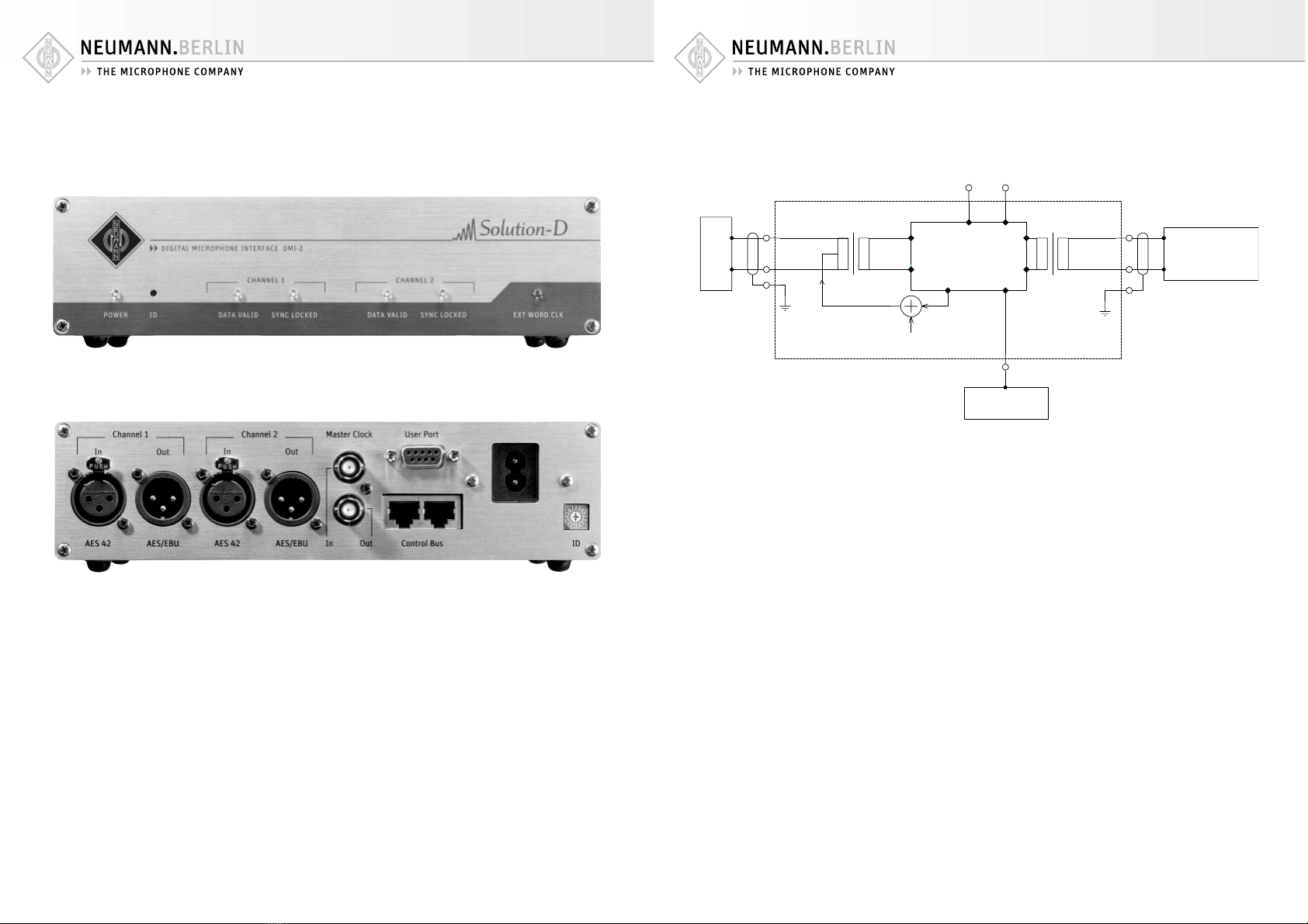
Abb. 1 / Fig. 1
Abb. 2 / Fig. 2
Digital
(Computer)
Receiver
IN OUT
AES42 AES/EBU
DPP( 10V)
Mic.
Control Data Control Data
Device
(e.g. Mix. Console)
Word Clock
Control Bus
DPP
Control
Abb. 3 / Fig. 3

Irrtümer und technische Änderungen vorbehalten • Errors excepted, subject to changes
Printed in Germany • Publ. 09/06 514791/A01
Konformitätserklärung
Die Georg Neumann GmbH er lärt, dass dieses Gerät
die anwendbaren CE-Normen und -Vorschriften erfüllt.
® Neumann ist in zahlreichen Ländern eine eingetragene
Mar e der Georg Neumann GmbH.
Declaration of Conformity
Georg Neumann GmbH hereby declares that this device
conforms to the applicable CE standards and regulations.
® Neumann is a registered trademar of the
Georg Neumann GmbH in certain countries.
Further product names used here are trademar s or registered trademar s of the respective manufacturers and here-
with will be accepted.
Table of contents
Languages:
Other Neumann.Berlin Recording Equipment manuals


