NEUTRIK NA2-IO-DPRO User manual

User Manual
NA2-IO-DPRO
for Mic, Line, AES I/O
to DANTETM Interface

2User Manual – DANTETM Adapter NA2-IO-DPRO | BDA 573 V1 2019/08
Imprint
Subject to change due to advances in technology! This user manual corresponds to the level of
technology at the time the product was delivered and not the current stage of development at
Neutrik.
If any pages or sections of this user manual are missing, please contact the manufacturer at the
address listed below.
Copyright
This user manual is protected by copyright. The user manual must not be duplicated, reproduced,
microfilmed or translated, nor must it be converted to be saved and processed in IT systems,
neither in the form of excerpts nor in full, without the express written authorization of Neutrik.
Copyright by: © Neutrik® AG
Manufacturer
Neutrik®AG
Im alten Riet 143
9494 Schaan
Liechtenstein
Phone: +423 2372424
Fax: +423 2325393
E: neutrik@neutrik.com
www.neutrik.com
Document Identification
Document No: BDA 573
Version: V1 2019/08
Language: English
Original language: English
Each user manual in a different language is a translation of the operating manual in English.

3User Manual – DANTETM Adapter NA2-IO-DPRO | BDA 573 V1 2019/08
Table of Contents
1 About this Document..............................................4
1.1 Significance of the user manual .............................4
1.2 Designations .........................................................4
1.3 Explanation of symbols .........................................5
1.3.1 Symbols in illustrations ....................................5
1.4 Target group .........................................................5
2 Safety........................................................................6
2.1 Warning information and signal words ..................6
2.2 Warning symbols ..................................................6
2.3 Important regulatory notes ...................................6
2.3.1 Declaration of conformity................................7
2.4 Important safety instructions.................................7
2.5 Intended use.........................................................7
2.6 Foreseeable improper use .....................................7
3 Components and Accessories .................................8
4 Description of the Product......................................9
4.1 What is the DPRO Adapter?...................................9
4.2 Device ..................................................................9
4.3 Connections and displays......................................9
4.3.1 Overview front ................................................9
4.3.2 Overview rear ...............................................10
4.3.3 Modes and switching logic of the
DPRO Adapter ....................................................... 11
4.4 DPRO Controller.................................................. 11
4.4.1 General overview .......................................... 11
4.4.2 Create Preset page........................................ 15
4.4.3 Load Preset page ..........................................16
4.4.4 Load Preset mismatch page........................... 17
4.4.5 Reset Devices window ..................................18
4.4.6 About Device (Device Settings) window ........18
4.4.7 Network Settings window............................. 19
4.4.8 Firmware Upgrade window........................... 19
4.4.9 About Software window...............................20
5 Operation ...............................................................21
5.1 Preparations ........................................................21
5.2 Connecting devices with the DPRO Adapter.......21
5.2.1 Power setup using a switch with PoE support 22
5.2.2 Power setup using a switch without PoE sup-
port.......................................................................22
5.3 Applications........................................................23
5.3.1 Redundant Mode ..........................................23
5.3.2 Switched Mode (Daisy-chained) ....................23
5.4 Linking devices with the DanteTM controller..........24
5.4.1 Enabling a DanteTM link ..................................24
5.5 DPRO Controller App ..........................................24
5.5.1 Downloading and installing DPRO Controller
App.......................................................................24
5.5.2 Connecting devices with the app ..................25
5.5.3 Selecting the device to edit ...........................25
5.5.4 Setting input parameters...............................25
5.5.5 Setting output parameters ............................26
5.5.6 Presets..........................................................27
5.5.7 Identify device...............................................30
5.5.8 Reset device..................................................31
5.5.9 Network Settings..........................................32
5.5.10 Firmware Upgrade.......................................33
5.6 Accessories assembly instructions........................34
5.6.1 Mounting brackets ........................................34
5.6.2 Rack panel....................................................35
6 After Operation .....................................................36
6.1 Dismounting devices ...........................................36
6.2 Transporting .......................................................36
6.3 Storage...............................................................36
6.4 Cleaning and care ...............................................36
6.5 Maintenance and repair ......................................36
6.6 Disposal..............................................................37
7 Appendix................................................................38
7.1 Technical specifications........................................38
7.2 PoE (Power over Ethernet) ...................................40
7.2.1 Definitions.....................................................40
7.2.2 PoE Standards ...............................................40
7.2.3 Classes and discovery process........................40

4User Manual – DANTETM Adapter NA2-IO-DPRO | BDA 573 V1 2019/08
About this Document
1 About this Document
This user manual provides an overview of the necessary operation steps and settings on the prod-
uct.
1.1 Significance of the user manual
This user manual is an integral component of the product and part of the product's safety
concept.
TMake sure that all persons who work with the product have fully read and also
understood this user manual.
TObserve all instructions exactly, especially the safety instructions.
This user manual contains important information on safely and properly operating the
product.
TKeep this user manual in the immediate vicinity of the product so personnel have access
to it at all times.
TPass this user manual on to every user, e.g., by lending it, or to the future owner of the product.
TIf this user manual is lost or damaged, a copy of it can be downloaded from the Neutrik's
website (www.neutrik.com).
1.2 Designations
Designation Explanation
DPRO Adapter DPRO Adapter NA2-IO-DPRO; to ensure the text is easy-to-read, the
device is hereinafter referred to as DPRO Adapter.
DanteTM audio
networking
DanteTM audio networking (hereinafter referred to as DanteTM) DanteTM
stands for Digital Audio Network Through Ethernet and is an audio
network protocol developed by the Australian company Audinate. DanteTM
delivers uncompressed, multi-channel, low-latency digital audio over a
standard Ethernet network using Layer 3 IP packets.
PoE Power over Ethernet; the device is supplied with power via the network
connection.
Peripheral devices Any device that can be connected to the DPRO Adapter: audio sources
(transmitters) and audio sinks (receivers)
Audio source Any device that emit an audio signal
Audio sink Any device that receives audio signals, such as loudspeakers, audio
systems (amplifiers, mixing consoles, etc.)
5User Manual – DANTETM Adapter NA2-IO-DPRO | BDA 573 V1 2019/08
About this Document
1.3 Explanation of symbols
Uniform safety instructions, symbols, terms and abbreviations were used to make this user manual
easier to understand. The following symbols designate instructions that are not relevant to safety,
but make the operating manual easier to understand.
OThe preconditions for an action are depicted with this symbol. Complete the items as listed be-
fore carrying out the action steps that follow.
TAction steps are designated by this symbol. Carry out the action steps in the order they are
presented.
The result of the action or the reaction of the product to the action are depicted with this
symbol.
•Lists without a mandatory sequence are presented as a list with this bullet.
1. Numbered listings are displayed in this manner.
(1) Refers to a position in an illustration.
Wherever you see this symbol, you will find useful information for safe, trouble-free opera-
tion of the product.
1.3.1 Symbols in illustrations
Symbol Explanation
Image position
Action steps numbered in an illustration.
Carry out the action steps in the order they are presented.
Only carry out these tasks when using OS X.
Only carry out these tasks when using Windows.
1.4 Target group
This user manual is intended for sound engineers and professional personnel who have detailed
experience in sound and event technology.
1
1

6User Manual – DANTETM Adapter NA2-IO-DPRO | BDA 573 V1 2019/08
Safety
2 Safety
2.1 Warning information and signal words
Special warning information regarding potential dangers inherent in a particular action are present-
ed before instructions for an action. The warnings are ranked as follows:
wCAUTION
Potential risk of danger!
This type of warning points out a situation that could result in minor or moderate injuries.
TMinor injuries may result if this warning is ignored.
wNOTE
Potential risk of property damage!
This type of warning points out a situation that could result in damage to the device and its
components.
TProperty damage may result if the warning is ignored.
2.2 Warning symbols
Symbol Warning
General warning
Warning of hearing impairment
2.3 Important regulatory notes
This equipment has been tested and found to comply with the limits for a Class B digital device,
pursuant to Part 15 of the FCC Rules. These limits are designed to provide reasonable protection
against harmful interference in a residential installation. This equipment generates, uses and may
radiate radio frequency energy and, if not installed and used in accordance with the instructions,
may cause harmful interference to radio communications. However, there is no guarantee that
interference will not occur in a particular installation. If this equipment does cause harmful inter-
ference to radio or television reception, which can be determined by turning the equipment off
and on, the user is encouraged to try to correct the interference by attempting one or more of the
following measures:
•Reposition or relocate the receiving antenna.
•Increase the distance between the equipment and receiver.
•Connect the equipment to an outlet on a circuit different from to the one that the receiver is
connected to.
•Consult the dealer or an experienced radio/TV technician for help.
wNOTE
Changes or modifications made to this equipment not expressly approved by Neutrik may void
the FCC authorization to operate this equipment.

7User Manual – DANTETM Adapter NA2-IO-DPRO | BDA 573 V1 2019/08
Safety
2.3.1 Declaration of conformity
The device meets all the relevant EU directives and therefore has the CE and EAC marking. The
Declaration of Conformity may be viewed at www.neutrik.com/en/approvals-and-certificates.
2.4 Important safety instructions
Avoid property damage to the DPRO Adapter due to unsuitable operating and environmental con-
ditions:
•Never immerse in water.
•Protect from strong sunlight.
•Never install the device near heat sources such as radiators, heating units, ovens or stoves.
•To avoid overheating, never cover the device.
•Protect the device from impact and above all, from falling from poles, stages, tables or furniture.
Repair
wNOTE
Property damage due to improper repair!
The DPRO Adapter does not contain any parts that you can repair yourself. Opening or repairing
the devices on your own may result in severe damage to the device.
TDo not open the housing of the DPRO Adapter under any circumstances.
TDo not change any parts yourself.
TOnly have the DPRO Adapter repaired by a authorized specialist dealer.
Information for operation
TEnsure that the ambient conditions specified for the DPRO Adapter are observed during
operation.
TDo not use the DPRO Adapter if it is not functioning properly, has fallen or been damaged, has
become wet or if parts of it have been immersed in water.
TIf disruptions occur during operation:
Immediately disconnect the DPRO Adapter from audio sources and/or audio sinks.
TDo not operate the DPRO Adapter in environments where flammable or explosive materials,
gases or vapors are present or might occur.
2.5 Intended use
The DPRO Adapter is designed for converting the signal of an analog LINE/MIC or digital AES/EBU
audio signal into a DanteTM signal. DanteTM signals can also be converted into analog LINE signals.
2.6 Foreseeable improper use
The DPRO Adapter is not suitable for use outdoors and in potentially explosive atmospheres.

8User Manual – DANTETM Adapter NA2-IO-DPRO | BDA 573 V1 2019/08
Components and Accessories
1 2
3
4
3 Components and Accessories
The device and the accessories can be ordered separately.
Pos. Description Item no.
1 DPRO Adapter (device) NA2-IO-DPRO
2Mounting brackets
(Kit includes 2 brackets, 2 fixing screws, 2 torx screws and 2 spacers)
NA-MB-KIT
3 Rack panel NRP1RU-2A
4Removable rubber protection NA-RC

9User Manual – DANTETM Adapter NA2-IO-DPRO | BDA 573 V1 2019/08
Description of the Product
4 Description of the Product
4.1 What is the DPRO Adapter?
The DPRO Adapter is a 2IN, 2OUT breakout box designed to connect legacy audio equipment to
the Dante network. It features high-quality microphone preamps and 2 Dante ports for either re-
dundant setup or daisy chaining. Audio parameters are adjusted by the DPRO Controller app.
All the connectors are lockable and, together with the removable rubber protector, offer a reliable
solution for tough stage conditions. With optional mounting brackets or a rack panel, the box can
be mounted below tables, in floor boxes, racks or on the truss.
4.2 Device
81011 9
1 52 4 63 7
4.3 Connections and displays
4.3.1 Overview front
1
2Pos. Description
1 Sheet metal housing
2Rubber protection (removable)
10 User Manual – DANTETM Adapter NA2-IO-DPRO | BDA 573 V1 2019/08
Description of the Product
Pos. Description
1Signal Present LED
Indicates the signal status.
•LED lights up green/yellow/red: signal available,
color indicates the signal level, see section
"Meter bar" on page 15.
•LED off: no signal.
2Phantom power 48V LED
Indicates, if Phantom power is active.
•LED lights up red: Phantom power active.
•LED off: Phantom power not active.
3HPF/Pad LED
Indicates, if HPF or Pad is active.
•LED lights up red: Pad
•LED lights up green: HPF
•LED flashs green and red: Pad and HPF active.
4Output MUTE LED
Indiates, if output is muted.
•LED lights up red: Mute active.
•LED off: Mute not active.
Pos. Description
5System Ready LED
Indicates the device's system status.
•LED lights up red: system is starting.
•LED lights up green: system is ready.
6Input type LED
Indicates the device input status.
•LED lights up green: Analog mode.
•LED lights up red: Digital mode.
7Output type LED
Indicates the device output status
•LED lights up green: Analog mode.
•LED lights up red: Digital mode.
8Balanced XLR output 2
•Output for analog/digital line signals.
9Balanced XLR output 1
•Output for analog line signal only.
10 Balanced XLR input 2
•Input for analog/digital line signals.
11 Balanced XLR input 1
•Input for analog line signal only.
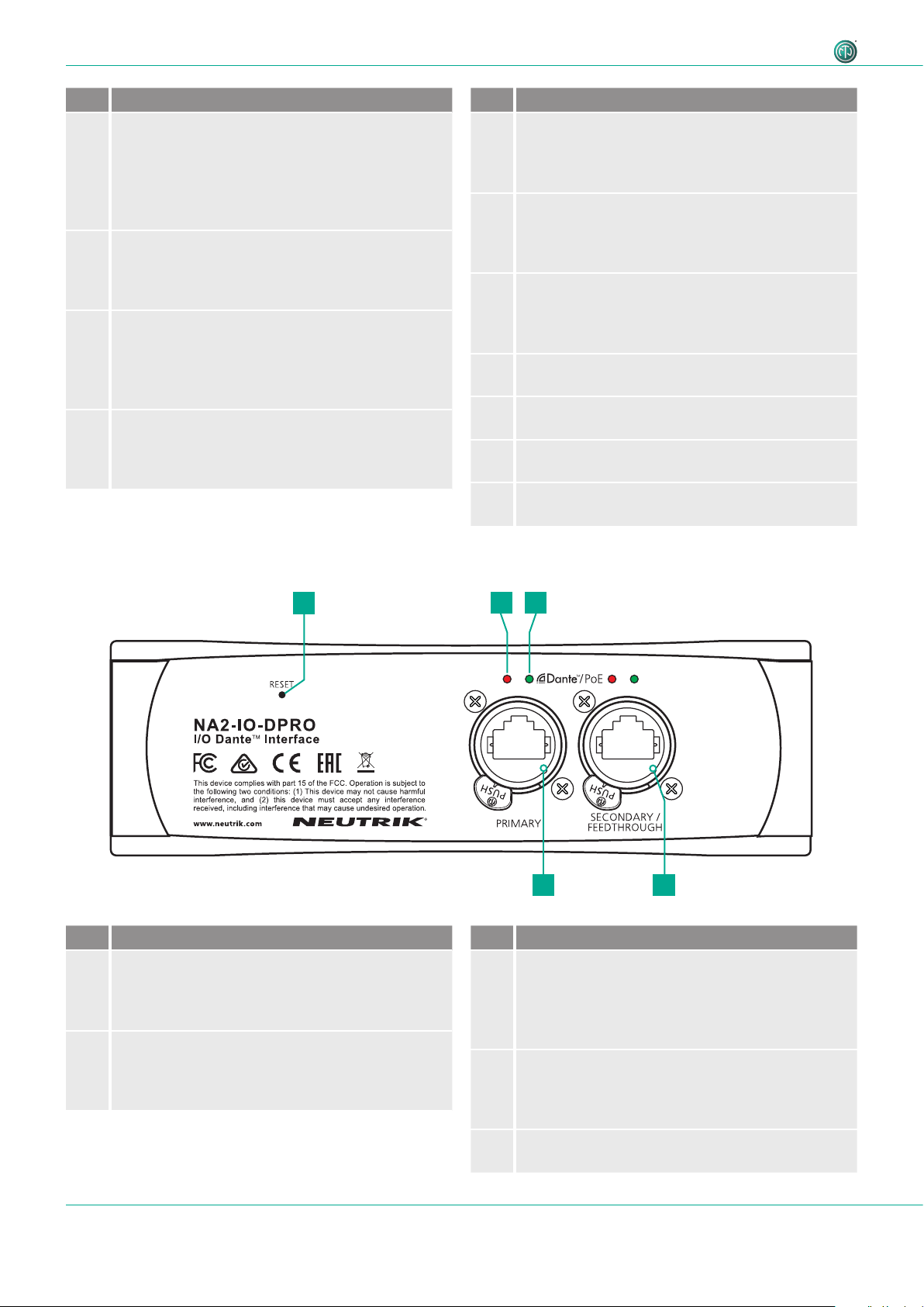
4.3.2 Overview rear
12 3
54
Pos. Description
1Reset Button
•Press to delete all set parameters.
A detailed description see in section "5.5.8
Reset device" on page 32.
2Link LED
Indicates the Ethernet connection status.
•LED is red: Ethernet connection is established.
•LED off: no Ethernet connection.
Pos. Description
3Active LED
Indicates the data transmission status.
•LED flashes green: data transmission
established.
•LED off: no data transmission.
4Secondary Network connection (RJ45)
Secondary Dante® Interface/Feedthrough/PoE
input (Redundant mode for standalone redundant
purpose, Switched mode for daisy-chaining)
5Primary Network connection (RJ45)
Primary Dante® Interface/PoE input
11User Manual – DANTETM Adapter NA2-IO-DPRO | BDA 573 V1 2019/08
Description of the Product
4.3.3 Modes and switching logic of the DPRO Adapter
Switchable contacts in the DPRO adapter work in 2 ways:
•If the signal is analog, connect channel 1 and channel 2 (valid for input and output).
•If the signal is AES, connect channel 2 only (valid for input and output).
AES carries 2 separate signals over 1 physical cable. Therefore AES is occupying both channels and channel 1 be-
comes inactive. It's not possible to combine an analog signal on channel 1 and AES on channel 2, as this would
mean 3 separate signals are present. In this case channel 1 will have a priority and only the analog signal will be
present. This is valid for input and output.
wCAUTION
Danger of hearing damage!
Signal peaks may occur as a consequence of incorrect connections.
TDo not connect AES/EBU signal to input 1.
TDo not connect amplifiers or other analog devices to output 2 (AES) if there is no connection on
output 1 (ANA).

12 User Manual – DANTETM Adapter NA2-IO-DPRO | BDA 573 V1 2019/08
Description of the Product
4.4 DPRO Controller
DPRO Controller allows to control audio parameters, monitor the status of the device, recall, save and load presets. The
app is available for PC and Mac.
4.4.1 General overview
Analog inputs and outputs
1
6
5
2
34
Pos. Description
1Menu
2 Device status
Shows the status of the selected device.
3Output settings
4Input settings
5 Link to Dante Controller
6 Connected devices
The selected device is marked with a green line on the left side.

13User Manual – DANTETM Adapter NA2-IO-DPRO | BDA 573 V1 2019/08
Description of the Product
Menu
Menu Option Shortcut Description
File Create Preset Ctrl/Cmd + N Opens a new Preset window.
Load Preset Ctrl/Cmd + L Applies created preset to devices.
Save As Preset Ctrl/Cmd + S Saves presets as .dap file on user's computer.
Quit Windows:
Alt + F4, Ctrl + Q
Mac: Cmd + Q
Quits the App.
Device Identify Device Ctrl/Cmd + I Identifies the selected device.
The LEDs on the front of the device flash red for 10 seconds.
Reset Device Deletes all set parameters on the selected device.
About Device Opens a window with general information of the selected
device.
Network Settings Opens a window with network settings.
Firmware Upgrade Opens a window with firmware information of the selected
device.
•Shows the version of the installed firmware.
•Install firmware upgrade.
Help About Software Opens a window with general information about the DPRO
Controller app and credits.
Further software functions/shortcuts
Option/Function Shortcut Description
Fader Ctrl/Cmd + click on
fader
Fader jumps to 0.
Device Status
This overview indicates the device status. The description of the LEDs can be found in chapter
"4.3.1 Overview front" on page 9.
Symbol Description
Identify device button
Click on the button to identify the selected device.
LEDs of XLR Inputs and XLR Outputs of the device flash up for 10 seconds.
Settings button
Click on the button to open the Settings window.

14 User Manual – DANTETM Adapter NA2-IO-DPRO | BDA 573 V1 2019/08
Description of the Product
Input Channels
Analog Inputs AES Inputs: Channel 1 becomes inactive
Symbol/button Description
Normal Active
Microphone/Line Signal button
Indicates, if the signal has MIC or LINE input sensitivity.
Click on the button to change the sensitivity.
Position MIC:Microphone level
Position LINE: Line level
Low-cut filter button
Activates the low-cut filter for the input signal.
+48V +48V Phantom power button (only with MIC signal)
Activate this function if the microphone requires phantom power.
PAD button
Activate this function to apply 16 dB attenuation.
Link/Unlink button
Click this button to link or unlink the input/output signals.
Gain (only with MIC signal)
Adjusts the input sensitivity.
15User Manual – DANTETM Adapter NA2-IO-DPRO | BDA 573 V1 2019/08
Description of the Product
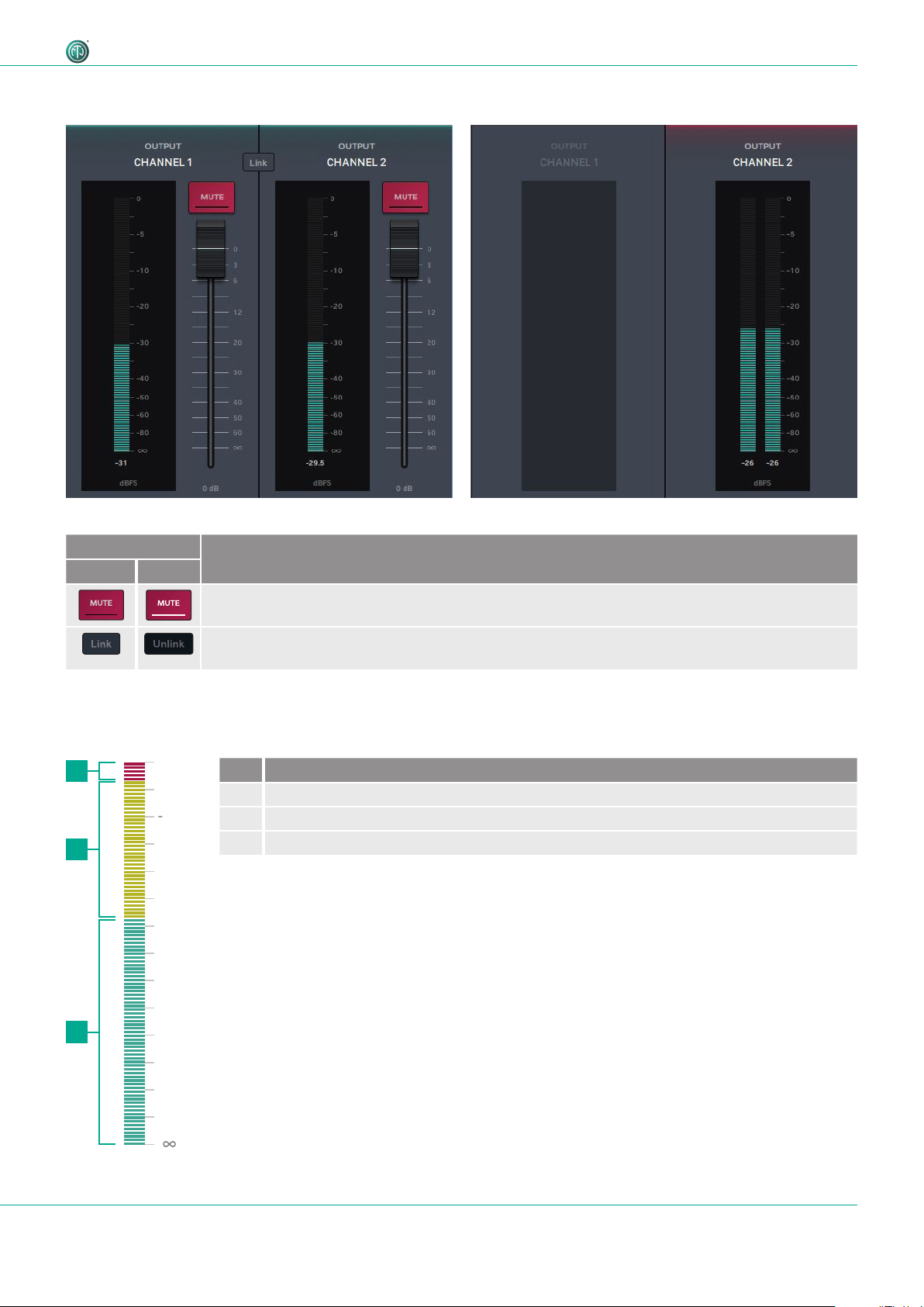
Analog Outputs AES Outputs: Channel 1 becomes inactive
Output Channels
Symbol/button Description
Normal Active
Mute button
Activate to mute the output signal.
Link/Unlink button
Click this button to link or unlink the input/output signals.
Meter bar
The Meter bar allows the signal level to be monitored on both input and output.
3
2
1Pos. Description
1 Red area: 0 dBFS to -3 dBFS
2 Yellow area: -3 dBFS to -18 dBFS
3 Green area: -18 dBFS to infinite
0
-
5
0
-
1
0
-
5
-
2
0
-
3
0
-
4
0
-
6
0
-
8
0
4
d
B
F
S
16 User Manual – DANTETM Adapter NA2-IO-DPRO | BDA 573 V1 2019/08
Description of the Product
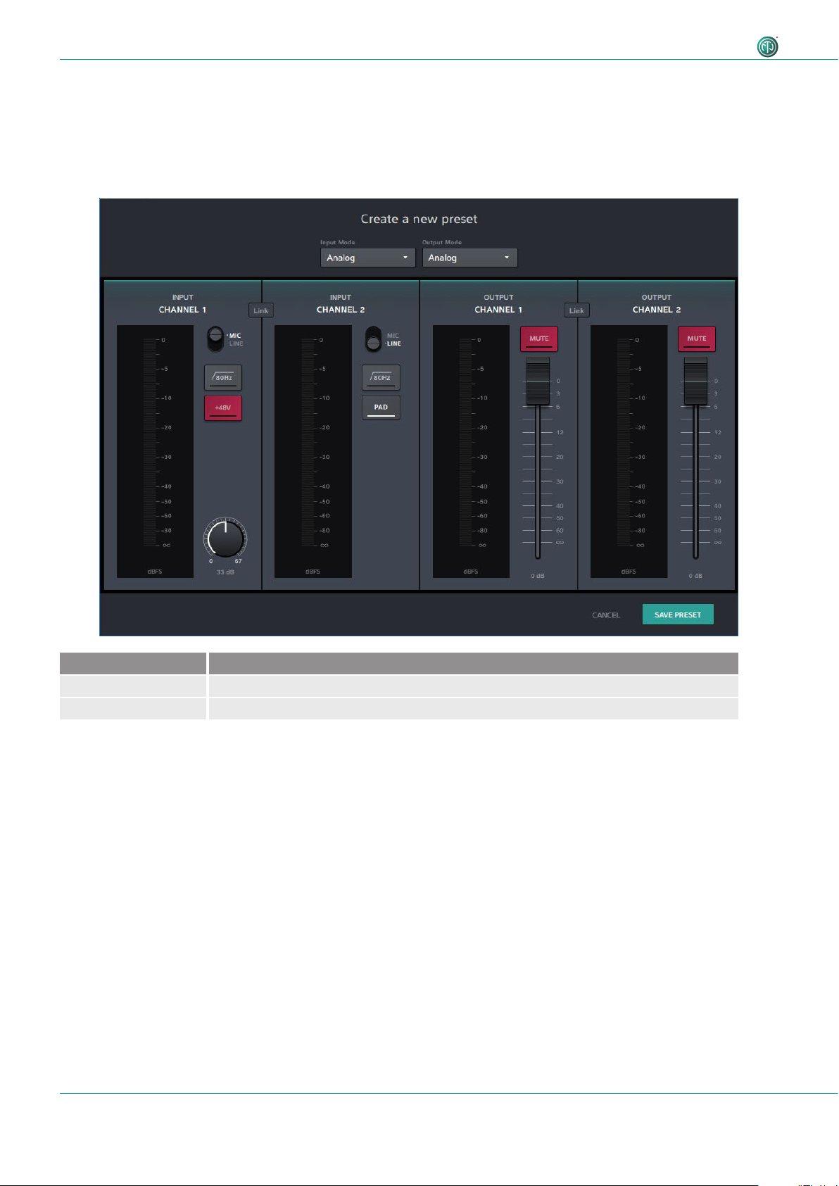
4.4.2 Create Preset page
With presets, settings of the devices can be stored for a later use. Presets can be also created and stored if no device is
connected or online. After adjusting the parameters, the preset can be saved as .dap file locally on the computer.
•Menu: File > Create Preset
•Shortcut: Ctrl/Cmd + N
Button / Screen text Description
CANCEL Close the window without saving the preset.
SAVE PRESET Save the preset as .dap file on the computer.
17User Manual – DANTETM Adapter NA2-IO-DPRO | BDA 573 V1 2019/08
Description of the Product
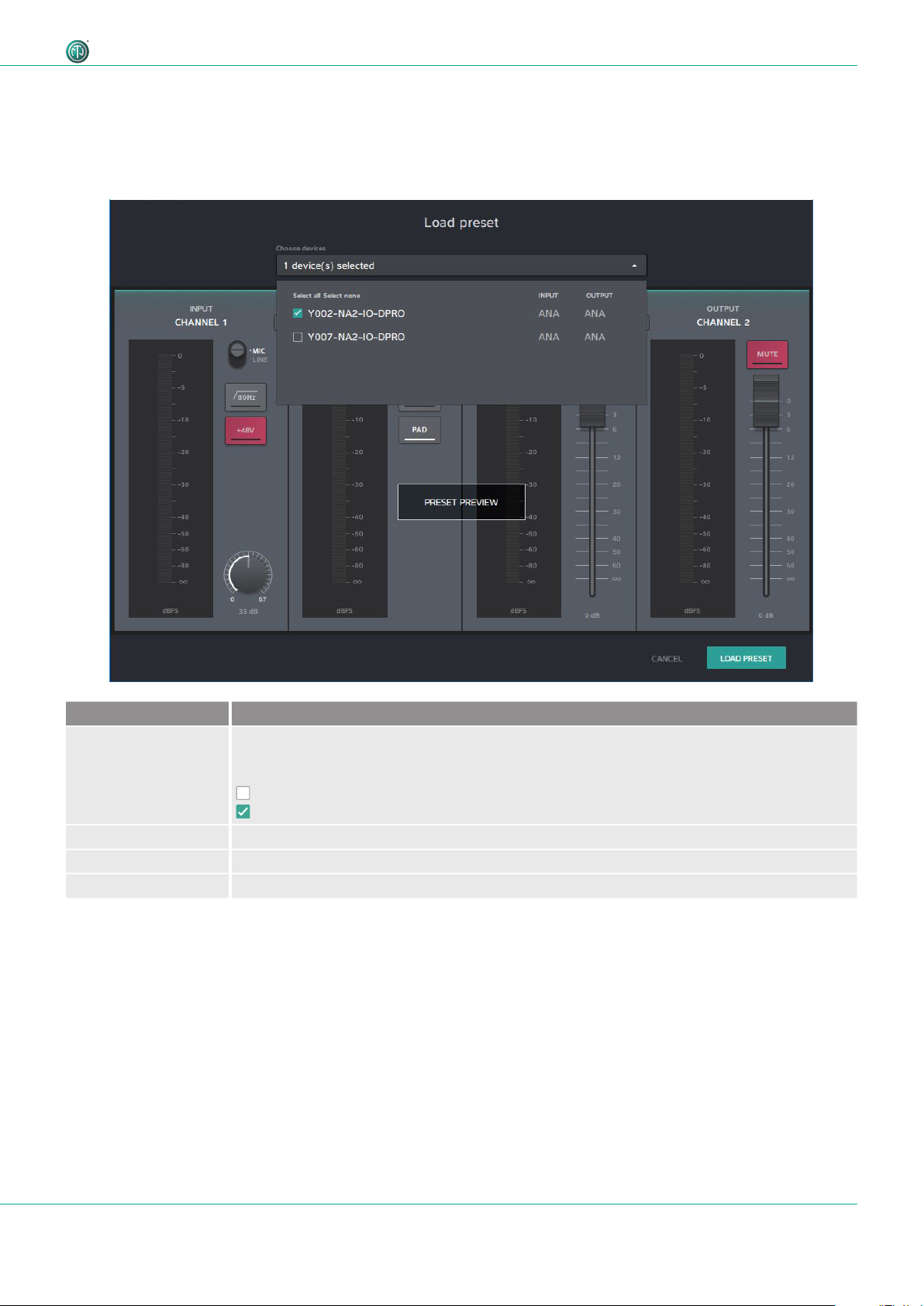
Button / Screen text Description
Choose devices Select the settings of one or more devices and load as preset.
Select all: Select all devices in the list.
Select none: Select no device in the list.
Checkbox: not selected
Checkbox: selected
PRESET PREVIEW Preview window of the settings which will be loaded with the preset.
CANCEL Close the window without loading the preset.
LOAD PRESET Load preset with the selected device settings.
4.4.3 Load Preset page
Load a preset from a .dap file from the computer.
•Menu: File > Load Preset
•Shortcut: Ctrl/Cmd + L

18 User Manual – DANTETM Adapter NA2-IO-DPRO | BDA 573 V1 2019/08
Description of the Product
Icon Description
Warining Icon.
Indicates a mismatch.
Mismatch
Loading of the preset(s) was not successful. The mode of the preset do not match with device mode (e.g. Preset is saved
with AES mode, device works in analog mode). More information about the modes and switching logic please find in
section "4.3.3 Modes and switching logic of the DPRO Adapter" on page 11.

19User Manual – DANTETM Adapter NA2-IO-DPRO | BDA 573 V1 2019/08
Description of the Product
4.4.4 Reset Devices window
This function resets the selected devices to factory settings. The reset function is described in section "5.5.8 Reset
device" on page 32.
•Menu: Device > Reset Device
Button / Screen text Description
CANCEL Close the window without resetting devices.
RESET DEVICES Reset selected devices to factory settings.
Select all: Select all devices in the list.
Select none: Select no device in the list.
not selected
selected
Button / Screen text Description
Device name Name of the selected device.
Device Firmware Current Neutrik firmware version installed on the device.
Dante Firmware Current Dante firmware version installed on the device.
IP Address IP address of the device in the network.
FIRMWARE
UPGRADE
Opens a window to upgrade the Neutrik's firmware on the device.
RESET DEVICE Reset device to factory settings.
4.4.5 About Device (Device Settings) window
This window shows general information about the selected device.
•Menu: Device > About Device
20 User Manual – DANTETM Adapter NA2-IO-DPRO | BDA 573 V1 2019/08
Description of the Product
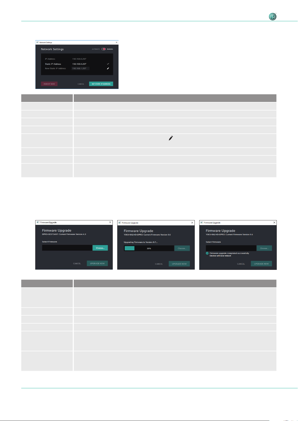
Button / Screen text Description
[Device Name]:
Current Firmware
Version X.X
Information about the current device firmware.
Select Firmware Select the downloaded upgrade file.
CANCEL Close the window without upgrading firmware.
UPGRADE NOW Install firmware from the selected upgrade file.
Upgrading
Firmware to
Version X.X
Progress bar informs about the firmware upgrade progress.
Firmware upgrade
completed
sucessfully
Information that firmware upgrade is complete. Device will reboot after sucessful upgrade.
Button / Screen text Description
AUTOMATIC The device obtains the IP address from DHCP server or locally from the computer.
MANUAL The device's IP address can be entered manually.
IP Adress IP address obtained from DHCP or local computer. Active, if AUTOMATIC is active.
Static IP Address Entered IP address by user. Checked IP address is active.
New Static IP
Address
Enter a new static IP address by clicking the icon.
REBOOT NOW Reboots the device.
CANCEL Close the window without any change.
SET STATIC IP
ADDRESS
Set the chosen static IP adress.
4.4.7 Firmware Upgrade window
Upgrade the Neutrik firmware on the device.
•Menu: Device > Firmware Upgrade
4.4.6 Network Settings window
Other manuals for NA2-IO-DPRO
1
Table of contents
Other NEUTRIK Recording Equipment manuals


Popular Recording Equipment manuals by other brands


Wheatstone Corporation
Wheatstone Corporation Talent Station TS-22 Technical manual

A&D
A&D GX-A Series instruction manual

Wildlife Acoustics
Wildlife Acoustics Song Meter SM2M+ Submersible User's manual supplement

JB Systems
JB Systems EC102/XO210 Operation manual

OHAUS
OHAUS Navigator instruction manual

Subzero
Subzero SZ-RS100 user manual


