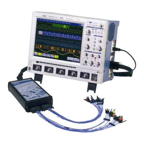
NEW BRUNSWICK SCIENTIFIC BioFlo 415 User manual

BioFlo 415
Benchtop SIP
Fermentor
MANUAL NO: M1360-0050
Revision D
December 15, 2008
NEW BRUNSWICK SCIENTIFIC
BOX 4005 •44 TALMADGE ROAD •EDISON, NJ 08818-4005
Telephone: 1-732-287-1200 •1-800-631-5417

ii
BioFlo 415 •M1360-0050 User’s Guide
INTERNATIONAL OFFICES:
BELGIUM
New Brunswick Scientific NV-SA
Stationsstraat 180/4
3110 Rotselaar
België/Belgique
Tel: 32 (0)16 56 28 31
Fax: 32 (0)16 57 27 53
GERMANY
New Brunswick Scientific GmbH
In Der Au 14
D-72622 Nürtingen
Deutschland
Tel: 49 (0)7022 932490
Fax: 49 (0)7022 32486
CHINA
New Brunswick Scientific Co., Inc.
A903, 904 Yin Hai Building
No. 250, Cao Xi Road
Shanghai 200235, P.R. China
Tel: 86 21 6484 5955 or 5966
Fax: 86 21 6484 5933
THE NETHERLANDS
New Brunswick Scientific BV
Kerkenbos 1101, 6546 BC Nijmegen
P.O Box 6826, 6503 GH Nijmegen
Nederland
Tel: 31 (0)24 3717 600
Fax: 31 (0)24 3717 640
FRANCE
New Brunswick Scientific SARL
12-14, Rond Point des Champs Elysées
75008 Paris
France
Tel: 33 (0)1 5353 1511
Fax: 33 (0)1 5353 1557
UNITED KINGDOM
New Brunswick Scientific (UK) Ltd.
17 Alban Park
St. Albans, Herts. AL4 0JJ
United Kingdom
Tel: 44 (0)1727 853855 or 0800 581331
Fax: 44 (0)1727 835666
Web: www.nbsuk.co.uk

iii
New Brunswick Scientific User’s Guide
WARNING!
This product is not designed to contain gases within the range of their
lower explosion limit (LEL) and their upper explosion limit (UEL).
If your process requires or produces gases, be sure to verify their LEL
and UEL concentration range (available online).
CAUTION!
This equipment must be operated as described in this manual.
If operational guidelines are not followed, equipment damage and personal
injury can occur. Please read the entire User’s Guide before attempting to use
this unit.
Do not use this equipment in a hazardous atmosphere or with hazardous
materials for which the equipment was not designed.
New Brunswick Scientific (NBS) is not responsible for any damage to this
equipment that may result from the use of an accessory not manufactured by
NBS.
WARNING!
High voltage.
Always make sure this equipment is properly grounded.

iv
BioFlo 415 •M1360-0050 User’s Guide
Copyright Notice
New Brunswick Scientific
Box 4005 44 Talmadge Road
Edison, New Jersey 08818-4005
©Copyright 2008 New Brunswick Scientific
All Rights Reserved.
Reproduction, adaptation, or translation without prior written permission from
New Brunswick Scientific is prohibited.
Disclaimer Notice
New Brunswick Scientific reserves the right to change information in this
document without notice. Updates to information in this document reflect our
commitment to continuing product development and improvement.
Manual Conventions
#NOTE:
Notes contain essential information that deserves
special attention.
CAUTION!
Caution messages appear before procedures which, if
caution is not observed, could result in damage to the
equipment.
WARNING!
Warning messages alert you to specific procedures or
practices which, if not followed correctly, could result in
serious personal injury.
Bold Text in boldface type emphasizes key words or
phrases.
This particular Warning message, whether found in the
manual or on the unit, means HOT SURFACE–and
therefore represents a potential danger to touch.
CRUSH WARNING!
Crush Warning messages alert you to specific
procedures or practices regarding heavy objects which,
if not followed correctly, could result in serious personal
injury .

v
New Brunswick Scientific User’s Guide
Every instrument manufactured by New Brunswick Scientific
is warranted to be free from defects in material and workmanship.
This apparatus with the exception of glassware, lamps and
electrodes (where supplied), is warranted for 1 year against faulty
components and assembly and our obligation under this warranty
is limited to repairing or replacing the instrument or part thereof,
which shall, within 1 year after date of shipment, prove to be
defective after our examination. This warranty does not extend
to any NBS products which have been subjected to misuse, neglect,
accident or improper installation or application; nor shall it extend
to products which have been repaired or altered outside the
NBS factory without prior authorization from
New Brunswick Scientific.
W A R R A N T Y

vi
BioFlo 415 •M1360-0050 User’s Guide
FERMENTOR/BIOREACTOR
INFORMATION SHEET
On this page, record the information for your fermentor/bioreactor and retain this for
future reference.
MODEL NUMBER: ________________________________
VOLTAGE: ________________________________
SERIAL NUMBER: ________________________________
The above information can be found on the electrical specification plate.
Purchased with the following installed options:
__________________________________________________
__________________________________________________
__________________________________________________
__________________________________________________
__________________________________________________

vii
New Brunswick Scientific User’s Guide
TABLE OF CONTENTS
1WARNINGS & CAUTIONS ........................................................................................................................ 1
1.1 WARNINGS .............................................................................................................. 1
1.2 CAUTIONS................................................................................................................ 1
2INSPECTION & UNPACKING OF EQUIPMENT ..................................................................................... 3
2.1 INSPECTION OF BOX(ES).............................................................................................. 3
2.2 PACKING LIST VERIFICATION...................................................................................... 3
2.3 BASIC COMPONENTS ................................................................................................... 3
3INTRODUCTION & OVERVIEW............................................................................................................... 4
3.1 SYSTEM ....................................................................................................................... 4
3.2 VESSELS ...................................................................................................................... 4
3.3 AGITATION SYSTEM .................................................................................................... 4
3.4 TEMPERATURE CONTROL ............................................................................................ 5
3.5 AERATION ................................................................................................................... 5
3.6 PHCONTROL ............................................................................................................... 5
3.7 DO CONTROL.............................................................................................................. 6
3.8 HIGH FOAM CONTROL................................................................................................. 6
3.9 EXHAUST SYSTEM ....................................................................................................... 6
3.10 SAMPLING/HARVESTING SYSTEM................................................................................ 6
3.11 RECOMMENDED ACCESSORIES &SUPPLIES................................................................. 7
3.12 SUPERVISORY SOFTWARE ........................................................................................... 7
4INSTALLATION .......................................................................................................................................... 8
4.1 PHYSICAL LOCATION .................................................................................................. 8
4.2 ENVIRONMENT ............................................................................................................ 8
4.3 INSTALLING THE CONTROL CABINET........................................................................... 8
4.4 INSTALLING THE TOUCHSCREEN.................................................................................. 8
4.5 UTILITIES .................................................................................................................. 10
4.5.1 Electrical Requirements...................................................................................11
4.5.2 Water and Drain Connections..........................................................................12
4.5.3 Gas Connections ..............................................................................................12
4.5.4 Exhaust Connection..........................................................................................12
4.6 VESSEL ASSEMBLY ................................................................................................... 13
4.6.1 Sparge & Exhaust Assemblies..........................................................................15
4.6.2 Other Ports & Plugs.........................................................................................17
4.6.3 Insert Probes .................................................................................................... 17
4.6.4 Install Motor Assembly.....................................................................................18
4.6.5 Connecting Vessel to Cabinet ..........................................................................18
4.7 ELECTRICAL CONNECTIONS ...................................................................................... 21
4.8 MAIN POWER SWITCH ............................................................................................... 21
4.9 OPTIONAL BIOCOMMAND PLUS ................................................................................ 22
4.10 INPUTS/OUTPUTS FOR ANCILLARY DEVICES ............................................................. 22
5SPECIFICATIONS ..................................................................................................................................... 24

viii
BioFlo 415 •M1360-0050 User’s Guide
5.1 CERTIFICATIONS........................................................................................................ 25
6OPERATING CONTROLS......................................................................................................................... 27
6.1 TOUCHSCREEN .......................................................................................................... 27
6.2 DISPLAY SCREENS..................................................................................................... 27
6.2.1 Touchscreen Calibration..................................................................................27
6.2.2 Start-Up Screen................................................................................................28
6.2.3 Summary Screen...............................................................................................28
6.2.4 Synoptic Screen ................................................................................................30
6.2.5 Gauge Screens..................................................................................................31
6.2.6 Adding Loops....................................................................................................32
6.2.7 Deleting Loops .................................................................................................33
6.2.8 Selecting Loop Control Modes.........................................................................34
6.2.9 Calibration Screen ...........................................................................................34
6.2.10 Cascade Screen ................................................................................................35
6.2.11 Trend Screen ....................................................................................................35
6.2.12 Pump Screen.....................................................................................................36
6.2.13 Alarm Summary Screen....................................................................................36
6.2.14 Sterilization Screen ..........................................................................................37
6.2.15 Setup Screen.....................................................................................................38
6.3 RS232/422 COMPUTER INTERFACE........................................................................... 39
7PROBE PREPARATION & CALIBRATION............................................................................................ 42
7.1 PHPROBE INSPECTION .............................................................................................. 42
7.2 PHPROBE CALIBRATION ........................................................................................... 42
7.2.1 pH Probe Installation.......................................................................................44
7.2.2 pH Probe Maintenance & Storage...................................................................45
7.3 DISSOLVED OXYGEN (DO) PROBE PREPARATION ..................................................... 45
7.3.1 Inspecting the DO Probe..................................................................................45
7.3.2 DO Probe Preparation.....................................................................................46
7.3.3 DO Probe Installation......................................................................................46
7.3.4 DO Probe Polarization ....................................................................................47
7.3.5 DO Probe Calibration: Setting Zero...............................................................47
7.3.6 DO Probe Calibration: Setting Span..............................................................48
8AUTOMATIC STERILIZATION............................................................................................................... 49
8.1 ESSENTIAL: BACKFLOW PREVENTION KIT............................................................ 49
8.2 STERILIZATION .......................................................................................................... 51
8.2.1 Priming the Water Jacket.................................................................................52
8.2.2 Sterilization Safety Features ............................................................................53
8.2.3 Starting a Sterilization Sequence .....................................................................53
8.2.4 Resetting Sterilization Parameters...................................................................55
8.3 VALVE SEQUENCING ................................................................................................. 56
8.4 STERILIZATION PHASE INDICATION ........................................................................... 58
8.5 ABORTING STERILIZATION ........................................................................................ 58
9PREPARING FOR FERMENTATION ......................................................................................................59
9.1 SYSTEMS CHECK ....................................................................................................... 59

ix
New Brunswick Scientific User’s Guide
9.2 ADDING MEDIA TO THE VESSEL ................................................................................ 60
10 GETTING STARTED................................................................................................................................. 61
10.1 CONTROL MODES...................................................................................................... 61
10.2 PUMP ASSIGNMENT ................................................................................................... 61
10.3 SETTING P&IVALUES ............................................................................................. 62
10.4 LOOP SETPOINTS ....................................................................................................... 62
10.4.1 Entering Setpoints............................................................................................62
10.4.2 Modifying Setpoints..........................................................................................63
10.5 DO CASCADE SYSTEM .............................................................................................. 63
10.6 USING LEVEL PROBES TO PROGRAM FEED PUMPS .................................................... 64
10.6.1 Setting a Feed Pump to Add Liquid .................................................................64
10.6.2 Setting a Feed Pump to Harvest.......................................................................64
10.6.3 Level Control Off..............................................................................................65
10.6.4 Pump Calibration.............................................................................................65
10.6.5 Exhaust Heater.................................................................................................66
11 CASCADE CONTROL............................................................................................................................... 67
11.1 CREATING A CASCADE .............................................................................................. 67
11.2 CONTROLLING DO BY CASCADE ............................................................................... 69
12 PLOTTING TRENDS ................................................................................................................................. 72
12.1 CREATING A TREND GRAPH ...................................................................................... 72
12.1.1 Using the Export Button...................................................................................74
12.1.2 Using the Zoom Button.....................................................................................75
12.1.3 Using the Read Line.........................................................................................75
13 ABOUT PUMPS ......................................................................................................................................... 77
13.1 PUMP SETPOINT......................................................................................................... 77
13.2 PUMP CONTROL MODE.............................................................................................. 78
13.3 PUMP FLOW RATE &CALIBRATION METHODS ......................................................... 79
13.4 PUMP PERIOD ............................................................................................................ 80
13.5 INSTALLING AN EXTERNAL VARIABLE SPEED PUMP ................................................. 80
14 ABOUT ALARMS...................................................................................................................................... 82
14.1 ABS AND DEV ALARMS ........................................................................................... 82
14.2 SETTING ALARMS...................................................................................................... 82
14.3 ACKNOWLEDGING AN ALARM ................................................................................... 84
14.4 ALARMS HISTORY ..................................................................................................... 85
15 USING THE SETUP SCREEN................................................................................................................... 87
15.1 CONTROLLER SETUP ................................................................................................. 87
15.1.1 Gas Control with 1 or No TMFC.....................................................................89
15.1.2 Gas Control with 2 TMFCs..............................................................................89
15.1.3 Gas Control with 3 TMFCs..............................................................................90
15.1.4 Gas Control with 4 TMFCs..............................................................................91
15.2 RECIPE MANAGER ..................................................................................................... 92
15.3 SYSTEM SETTINGS..................................................................................................... 93

x
BioFlo 415 •M1360-0050 User’s Guide
15.3.1 Resetting Date/Time.........................................................................................94
15.3.2 Updating Software............................................................................................94
15.4 HARDWARE SETUP .................................................................................................... 94
15.5 SECURITY SETTINGS.................................................................................................. 96
16 OPERATION............................................................................................................................................... 98
16.1 LOAD PUMP TUBING ................................................................................................. 98
16.2 INSTALL LIQUID ADDITION SYSTEMS...................................................................... 100
16.2.1 Addition Tubing Size ......................................................................................101
16.3 INOCULATION.......................................................................................................... 102
16.4 LAUNCH BIOCOMMAND (IF PRESENT) ..................................................................... 102
16.5 SAMPLING PROCEDURE ........................................................................................... 102
16.6 HARVESTING ........................................................................................................... 104
16.7 FERMENTATION PHASES.......................................................................................... 104
16.7.1 Lag Phase.......................................................................................................105
16.7.2 Exponential Growth Phase.............................................................................105
16.7.3 Steady State Phase .........................................................................................105
16.7.4 Decline Phase.................................................................................................105
16.8 BATCH OPERATION ................................................................................................. 105
16.9 FED BATCH OPERATION .......................................................................................... 105
16.10 CHEMOSTAT OPERATION..................................................................................... 106
16.11 SHUTDOWN PROCEDURE ..................................................................................... 107
17 CLEANING............................................................................................................................................... 108
17.1 CLEANING THE VESSEL ........................................................................................... 108
17.1.1 List of Wetted Parts........................................................................................108
17.2 CLEANING THE CABINET ......................................................................................... 109
18 MAINTENANCE...................................................................................................................................... 110
18.1 PHPROBE MAINTENANCE AND STORAGE................................................................ 110
18.2 DO PROBE MAINTENANCE AND STORAGE .............................................................. 110
18.3 VESSEL &TUBING................................................................................................... 111
18.4 PERIODIC INSPECTION ............................................................................................. 111
18.5 FUSE REPLACEMENT ............................................................................................... 111
18.6 PORT &ADAPTER O-RINGS .................................................................................... 111
18.7 HEADPLATE O-RING REPLACEMENT ....................................................................... 111
18.8 REPLACEMENT PARTS ............................................................................................. 112
19 SERVICE .................................................................................................................................................. 113
19.1 TROUBLESHOOTING................................................................................................. 113
19.2 SERVICE PARTS ....................................................................................................... 115
20 DRAWINGS.............................................................................................................................................. 116
20.1 LIST OF DRAWINGS ................................................................................................. 119
20.2 LIST OF TABLES....................................................................................................... 121
21 APPENDIX A: SOME GENERAL CONCEPTS..................................................................................... 122
21.1 WHAT IS A CONTROLLER?....................................................................................... 122

xi
New Brunswick Scientific User’s Guide
21.2 WHAT IS A CONTROL LOOP? ................................................................................... 122
21.3 WHAT IS PROBE CALIBRATION? .............................................................................. 123
21.4 WHAT ARE P-I-D CONSTANTS?............................................................................... 123
21.5 WHAT IS P-I-D TUNING?......................................................................................... 124
21.6 WHAT DO THE CONSTANTS MEAN? ........................................................................ 125
22 APPENDIX B: OTR................................................................................................................................. 126
22.1 DETERMINING AN OXYGEN TRANSFER RATE .......................................................... 126
22.1.1 OTR Calculations...........................................................................................126
22.2 SOME FACTORS THAT AFFECT OTR AND HORSEPOWER......................................... 127
23 APPENDIX C: FERMENTATION TECHNIQUES................................................................................ 128
23.1 MEDIA FORMULATION ............................................................................................ 128
23.2 ANTIFOAM FORMULATION ...................................................................................... 129
23.3 TUBING SIZE............................................................................................................ 129
23.4 ACID &BASE .......................................................................................................... 130
23.5 GLUCOSE FEED........................................................................................................ 130
23.6 RECOMMENDED PROCESS CONTROL SETTINGS ....................................................... 131
24 APPENDIX D: CORROSION RESISTANCE TABLES......................................................................... 132
25 APPENDIX E: GENERAL CHARACTERISTICS OF EPR................................................................... 147
25.1 IDENTIFYING EPR ................................................................................................... 147
25.2 GENERAL CHARACTERISTICS .................................................................................. 147
26 INDEX....................................................................................................................................................... 148


1
New Brunswick Scientific User’s Guide
1
1
W
WA
AR
RN
NI
IN
NG
GS
S
&
&
C
CA
AU
UT
TI
IO
ON
NS
S
The following section is a recap of all WARNING and CAUTION messages contained in
this manual. This information is essential to the safe operation of your BioFlo 415. Please
take a moment to acquaint yourself with the content of each message.
Page numbers are provided so you can review each message in its entirety and acquaint
yourself with its overall context.
1.1 WARNINGS
WARNING Page
High voltage. Always make sure this equipment is properly grounded. iv, 11, 21
This product is not designed to contain gases within the range of their
LEL and their UEL… iv
Do not use this equipment in a hazardous atmosphere or with hazardous
materials for which the equipment was not designed. 10, 12
Prime the water system before the first use of the vessel and every time the
vessel has been detached then reattached.
18
To avoid possible safety hazard, the BioFlo 415 Backflow Prevention Kit
must be installed in the water inlet line before performing a sterilization cycle. 49
Be sure to wear protective gloves when you move the sparge valve from
sterilization to sparge position.
54
Never turn the heater off during a run or the exhaust filter may clog. 66
Be careful not to pinch your fingers in the pump head levers. 100
Always turn your BioFlo 415 off and disconnect the power cord before
performing maintenance. 110, 113
1.2 CAUTIONS
CAUTION Page
This equipment must be operated as described in this manual. If
operational guidelines are not followed, equipment damage and personal injury
can occur. Please read the entire User’s Guide before attempting to use this
unit. Do not use this equipment in a hazardous atmosphere or with
hazardous materials for which the equipment was not designed. NBS is
not responsible for any damage to this equipment that may result from the use
of an accessory not manufactured by NBS.
iv
Before making electrical connections, verify that the supply voltage matches
the voltage and the power requirements marked on the electrical specification
plate (located on the rear panel of the cabinet) and the control schematics
supplied with the unit.
9, 11, 21
Never use a wrench on headplate ports; only finger tighten the adapters. 14, 15
...continued...

2
BioFlo 415 yM1360-0050 User’s Guide
CAUTION Page
On initial set-up, prior to operation, check that all impellers are tightly
fastened to the drive shaft. 18
As soon as the heater is connected to the Control Cabinet, you must make sure
there is water in the vessel jacket. Do not plug the heater cable in to the
cabinet unless the vessel jacket has been primed.
21
Before turning on the main power switch, make sure that: (1) the input water
hose is connected, the drain line is connected and the water supply is turned on;
(2) the vessel is in place and the quick-connect water lines are connected to the
vessel’s heat exchanger; (3) the power cord is properly connected to the control
cabinet and plugged into a suitable power outlet.
22
Be sure to wear protective gloves when installing a glass electrode. 44
We recommend that you avoid the use of hydrochloric acid (HCl)
with the BioFlo 415 for pH control or any other purpose, because HCl corrodes
stainless steel. Over time, it will severely damage the vessel, a costly
component to replace, and other stainless steel components.
Phosphoric and sulfuric (10% maximum concentration) acids are acceptable and
are commonly used for pH control.
45
Never let a pH probe rest on its tip, and never leave a pH probe in DI water. 45, 110
There must be liquid in the vessel for sterilization. Never begin the
sterilization process if the vessel is empty.
49
If Sterilization Temperature does not reach 121.5ºC, make sure the water
supply pressure is not too high (max. 10 PSIG).
49
Proper installation of the RTD is essential to temperature control. 59
Proper pH control is critically dependent on tubing size, which should be as
small as possible. Consult Table 9 in Section 13.3 for guidance. 65, 99
When selecting an external pump to operate with your system, please
consult with your local sales representative to be sure the model you choose is
compatible with your BioFlo 415.
80
Be sure to set the dip switches correctly when using either 4-20mA or 0-5V
inputs/outputs. 81
Acknowledging alarms is NOT a replacement for correcting the condition
that triggered the alarm. Diagnose the cause of the alarm condition and rectify
the situation to ensure proper operation of your BioFlo 415.
85
Never clean the vessel or its components or the control cabinet with abrasive
chemicals or materials.
108
Never let a DO probe rest on its tip. 110

3
New Brunswick Scientific User’s Guide
2
2
I
IN
NS
SP
PE
EC
CT
TI
IO
ON
N
&
&
U
UN
NP
PA
AC
CK
KI
IN
NG
G
O
OF
F
E
EQ
QU
UI
IP
PM
ME
EN
NT
T
2.1 Inspection of Box(es)
When you have received your order from New Brunswick Scientific, carefully inspect
all parts of the shipment for damage that may have occurred during shipping. Report
any damage immediately to the carrier and to your local NBS Sales Order Department.
2.2 Packing List Verification
Verify against your NBS packing list that you have received the correct materials.
Report any missing parts to your local NBS Sales Order Department.
2.3 Basic Components
You should have at least the following components, which will be described in greater
detail later in this manual:
•Control Cabinet •Filters
•Touchscreen •Motor
•Vessel (components installed) •Hoses/Tubing
•Sampling/Harvesting Connections •Probe Kits (pH, DO, Foam, Level)
#NOTE:
The assembled Control Cabinet/Touchscreen assembly is called a Control
Station. For purposes of clarity in this manual, however, the control
cabinet (which houses the controller) and the touchscreen will be referred
to separately by their component names.

4
BioFlo 415 yM1360-0050 User’s Guide
3
3
I
IN
NT
TR
RO
OD
DU
UC
CT
TI
IO
ON
N
&
&
O
OV
VE
ER
RV
VI
IE
EW
W
3.1 System
BioFlo 415 is a versatile sterilizable-in-place (SIP) fermentor that provides a fully
equipped system in one compact package. It can be employed for batch or continuous
culture with process control of pH, dissolved oxygen (DO), agitation, temperature,
pump feed, antifoam, level and addition analog/digital inputs and outputs.
3.2 Vessels
The fermentation vessels are designed for total volumes of 7, 14 and 19.5 liters.
Each stainless steel vessel consists of a headplate, view window and magnetic drive
agitation with Rushton impellers. Ports are provided in the headplate for the following
purposes: inoculation; base and acid addition; a thermowell for a resistance
temperature detector (RTD); a foam probe; a sparger; a harvest tube; a sampling tube;
an exhaust condenser; and dissolved oxygen (DO) and pH electrodes. The drive
bearing housing is also located on the headplate (see Figures 3a, 8, 9 and 10).
3.3 Agitation System
A removable agitation motor located on top of the bearing housing on the headplate is
connected to the agitation shaft with a magnetic drive coupling.
The motor will provide a speed range from 50 to 1000 RPM. The process-control
software ensures agitation speed control from ±1 RPM to ±5 RPM throughout the
speed range.
It is possible to cascade Dissolved Oxygen (DO) to Agitation (AGIT) so the agitation
speed will vary between the user-specified minimum and maximum setpoints in order
to maintain the set percentage of DO. (See Section 11 for further information on
setting up cascades.)
Default P & I (proportional & integral) values are preset at the factory. We strongly
recommend that you maintain the factory-set parameters.

5
New Brunswick Scientific User’s Guide
3.4 Temperature Control
The culture temperature setpoint may be selected within the range from 5°C above
coolant temperature to 80°C (±0.1°C). It is controlled by the process-control
software. The media temperature is sensed by a Resistance Temperature Detector
(RTD) submerged in the thermowell.
Default P & I (proportional & integral) values are preset at the factory. We strongly
recommend that you maintain the factory-set parameters.
3.5 Aeration
Up to four gases, including air, nitrogen, carbon dioxide and oxygen, can be
introduced into the media through the ring sparger. The flow rate is controlled
automatically by one, two, three or four thermal mass flow controller(s), according to
the definition of your system. The thermal mass flow controller is regulated
automatically according to values set via the control cabinet touchscreen. If you wish
to use a rotameter, there is an option for no thermal mass flow controller.
The percentage of oxygen blended with the sparge air can be controlled manually by
the user or automatically through the controller by applying the O2enrichment
function. (For further information on cascading, see Section 11.)
3.6 pH Control
pH is controlled in the range of 2.00-12.00 (±0.01). The pH is sensed by a Gel-filled
pH probe (see Figures 32a & 32b). Control is maintained by a P & I (proportional &
integral) controller which operates two peristaltic pumps, assigned to acid and base
addition ports, or controls the use of gas(es) for this purpose. The user can also select
a deadband value to control pH within the user-assigned range: no acid or base will be
added when the pH value falls within the deadband tolerance above or below the
setpoint.
Default P & I (proportional & integral) values are preset at the factory. We strongly
recommend that you maintain the factory-set parameters.

6
BioFlo 415 yM1360-0050 User’s Guide
3.7 DO Control
DO is controlled in the range of 0-200% (±1%). It is sensed by the DO electrode and
control is maintained by the P & I controller by changing the speed of agitation, the
thermal mass flow controller-regulated flow rate (if your system is so equipped),
nutrient addition, and/or the percentage of oxygen in aeration. The DO probe is a
polarographic probe.
Default P & I (proportional & integral) values are preset at the factory. We strongly
recommend that you maintain the factory-set parameters.
3.8 High Foam Control
Foam can be controlled during batch fermentation by a level probe located in the
headplate. The controller operates the antifoam-assigned pump that adds chemical
defoamer into the vessel as needed.
3.9 Exhaust System
The exhaust gases pass into the exhaust condenser (see Figure 5) where moisture is
removed; any residual moisture is heated past the dewpoint via the heating pad,
allowing it to pass through the exhaust filter with a reduced potential for clogging.
3.10 Sampling/Harvesting System
The sampler assembly consists of the sampler tube with a sampler needle, three tri-
clamps and a sampler valve. This assembly facilitates the aseptic removal of the
sample, or harvesting the entire contents of the vessel, to an optional sample/harvest
vial or bottle.

7
New Brunswick Scientific User’s Guide
3.11 Recommended Accessories & Supplies
Before you begin to assemble your BioFlo 415, it would be prudent to verify that you
have all of the following accessories and supplies readily at hand:
•Rubber gloves •Media
•Silicone tubing •Antifoam agent
•A tie gun •pH 4 buffer
•Plastic ties •pH 7 buffer
•Plastic tubing connectors •Silicone O-ring lubricant
•Addition bottles •An inoculation syringe
•A liquid trap
A spare parts kit is available from NBS (part number M1360-9969; see Section 19.2)
with many of the commonly required items, including a selection of tubing, clamps,
filters, connectors and addition vessels. Speak to your NBS sales representative for
more information.
3.12 Supervisory Software
In addition to the built-in software that you interface with through the touchscreen,
your BioFlo 415 system can be remotely controlled from a PC via NBS BioCommand
Plus optional supervisory software (see Section 4.9).

8
BioFlo 415 yM1360-0050 User’s Guide
4
4
I
IN
NS
ST
TA
AL
LL
LA
AT
TI
IO
ON
N
4.1 Physical Location
The surface on which you place the BioFlo 415 fermentor should be smooth, level and
sturdy. Ensure that the surface can bear the weight of the fermentor plus vessel contents
and any applicable ancilliary equipment.
Also ensure that there is enough space around the back and the front of the BioFlo 415 for
proper operation and access. Allow at least 4 inches of clearance behind the unit for heat
dissipation. See Section 5, Specifications, for weights and dimensions.
4.2 Environment
The BioFlo 415 fermentor operates properly under the following conditions:
•Ambient temperature range 10°C to 30°C
•Relative humidity up to 80% non-condensing
4.3 Installing the Control Cabinet
Position the BioFlo 415 control cabinet on a firm, level surface in an area where
utilities are readily available.
Level the horizontal surface of the base with four leveling glides if necessary.
Connect the power cord to the rear of the control cabinet. At a later time, once the unit
is completely assembled and all connections have been made, you will plug the power
cord into a suitable electrical outlet.
4.4 Installing the Touchscreen
With reference to Figures 1a (for location) & 1b, align the monitor with the mounting
rack on the cabinet, and use the four screws provided with the monitor to securely
fasten it to the rack. The mounting rack swivels for easy access.
With reference to Figure 1b, connect the cabinet’s power cord plug, com port
connector and VGA monitor connector to the bottom of the touchscreen monitor.
Table of contents

