Page 2 of 70 Released 10/12/2021 Page 3 of 70Released 10/12/2021
AGATE TECHNOLOGY AT2040
AGATE TECHNOLOGY AT2040
Table of Contents
Introduction................................................................................................................................................ 4
Product Technical Support ..................................................................................................................... 4
2-Year Limited Warranty ......................................................................................................................... 4
Disclaimer ............................................................................................................................................... 4
Copyright ................................................................................................................................................ 4
Safety information ..................................................................................................................................... 5
Primary functions ...................................................................................................................................... 6
Maximum weight recommendations ....................................................................................................... 6
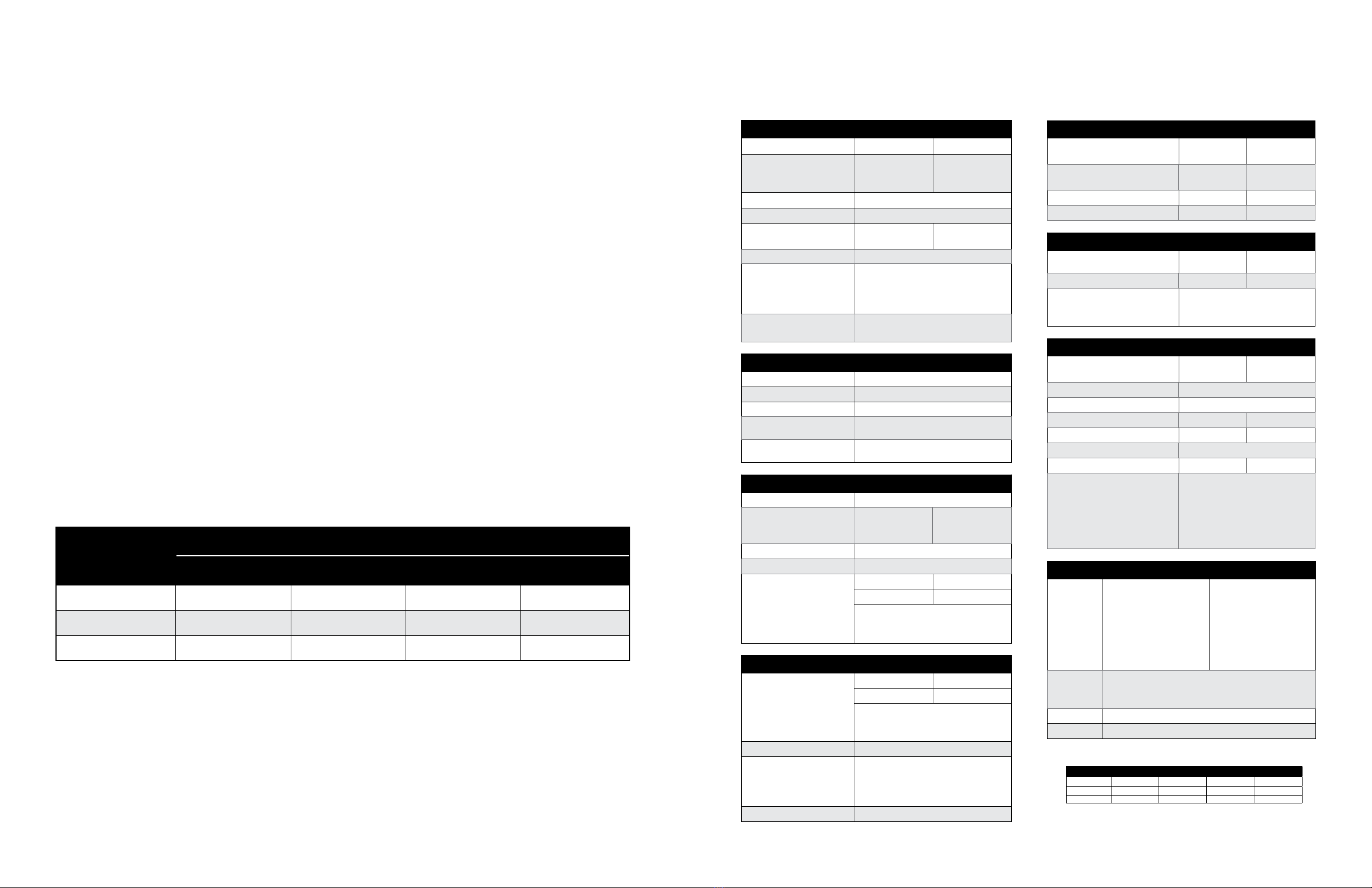
Specications and performance.............................................................................................................. 7
Instrumentation and control system ....................................................................................................... 8
Physical overview.................................................................................................................................... 10
AT2040 accessories................................................................................................................................. 12
Battery operation..................................................................................................................................... 13
Operation instructions ........................................................................................................................... 14
Main Menu Screen Overview................................................................................................................ 14
Navigating the AT2040 Menu................................................................................................................ 16
Using the Frequency and Amplitude Knobs ................................................................................... 16
Using the Touchscreen.................................................................................................................... 16
Using the Adjustable Displays ........................................................................................................ 16
Editing a Text Field.......................................................................................................................... 16
Using the Keyboard and Number Pad............................................................................................ 16
Using Toggle Buttons...................................................................................................................... 16
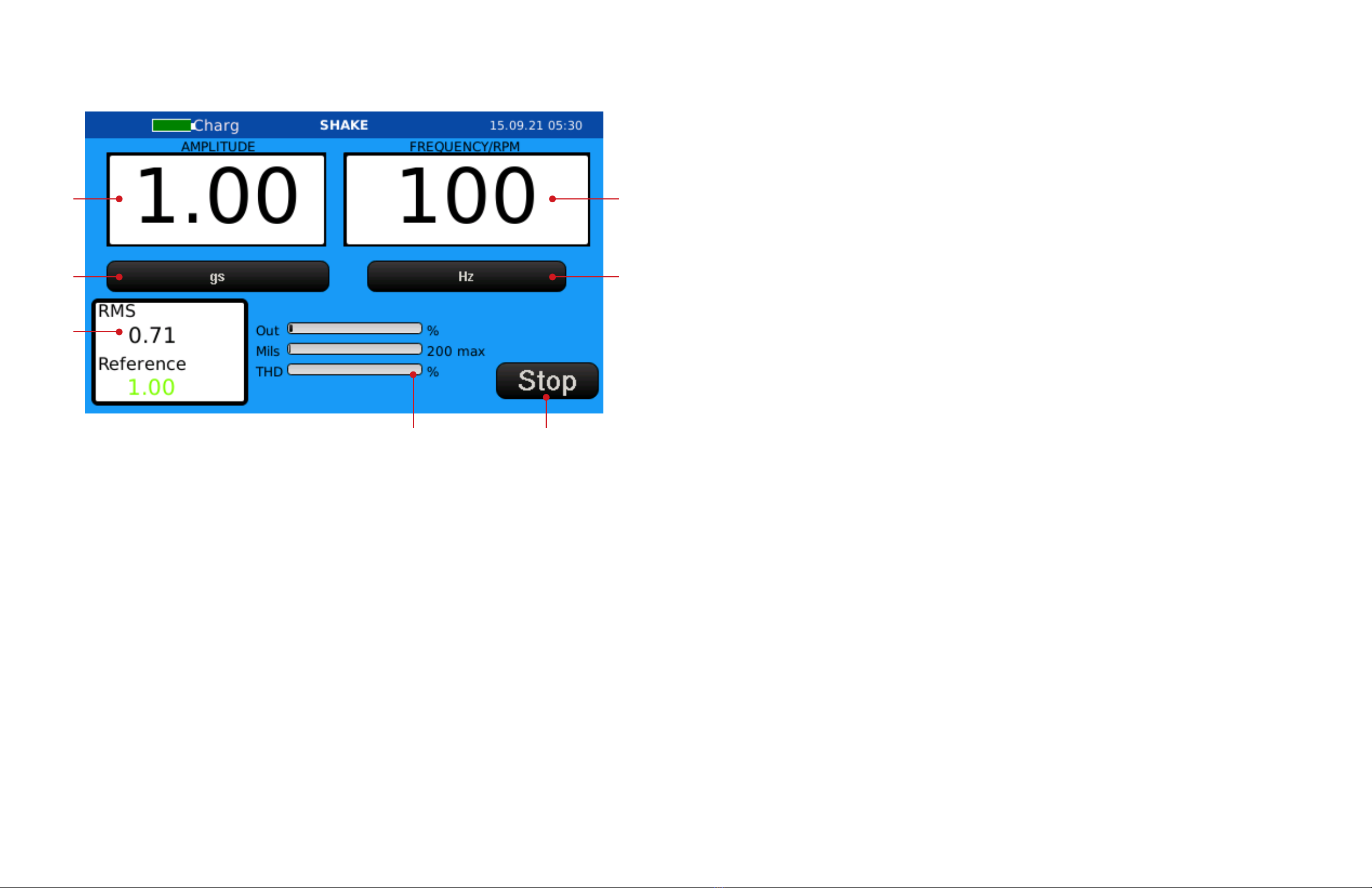
Shake Mode.......................................................................................................................................... 17
Shake Mode Screen Overview........................................................................................................ 18
Conducting a Test in Shake Mode.................................................................................................. 19
Purewave™ Overview ..................................................................................................................... 19
Test Mode ............................................................................................................................................. 20
Testing in Manual Mode ................................................................................................................. 22
Testing in Automatic Mode ............................................................................................................ 23
Calibrating IEPE Accelerometers .................................................................................................... 24
Calibrating Charge Accelerometers ................................................................................................ 25
Calibrating 4-20mA Transmitters .................................................................................................... 26
Calibrating Triaxial Sensors ............................................................................................................ 28
Calibrating Proximity Probes ......................................................................................................... 29
Setup Mode .......................................................................................................................................... 38
Deleting and Saving Previous Test Records ................................................................................... 39
Adjusting Date and Time Zone........................................................................................................ 43
Network Setup ................................................................................................................................ 44
Calibration and Company Name..................................................................................................... 45
Exporting and Importing PDF Certicate Files ............................................................................... 46
Simulation Mode................................................................................................................................... 48
Controlling the AT2040 remotely............................................................................................................ 50
Install and Setup VNC Viewer ............................................................................................................... 50
Setting up a custom sensor ................................................................................................................... 53
Designing a Custom Sensor ................................................................................................................. 53
Adding a Test Point ......................................................................................................................... 54
Deleting a Test Point ....................................................................................................................... 54
Saving a Custom Sensor ...................................................................................................................... 56
Uploading a Saved Custom Sensor...................................................................................................... 56
Deleting a Custom Sensor .................................................................................................................... 59
Customizing the PDF certicate template............................................................................................ 60
HTML Tags............................................................................................................................................ 61
HTML Tips....................................................................................................................................... 61
HTML Keywords ................................................................................................................................... 62
Product maintenance.............................................................................................................................. 68
AT2040 Recalibration............................................................................................................................ 68
Battery .................................................................................................................................................. 68
Service Notes........................................................................................................................................ 68
Operator notes......................................................................................................................................... 68
A2LA accreditation.................................................................................................................................. 69