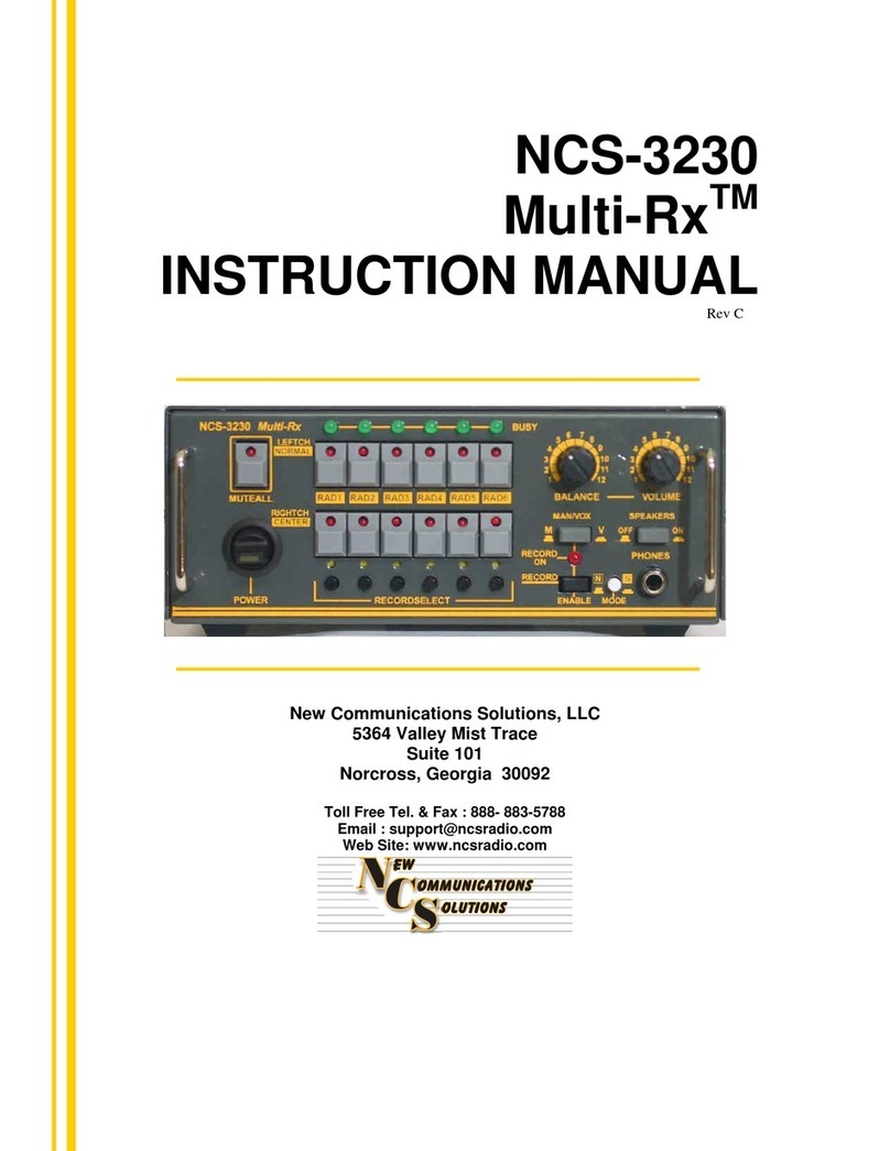
New Communications Solutions NCS-3203 Multi-Rx II User manual

NCS-3203
Multi-Rx II
INSTRUCTION MANUAL
Rev A
Including 3240-3203 Application Notes
New Communications Solutions, LLC
5364 Valley Mist Trace
Suite 101
Norcross, Georgia 30092
Toll Free Tel. & Fax : 888- 883-5788
Web Site: www.ncsradio.com

NCS-3203 Rev A Instruction Manual Copyright © 2005 New Communications Solutions, LLC
2
Introduction
The Multi-RxII was designed to provide a flexible way to monitor and control the
receive audio of multiple receivers. The Multi-Rx IIworks with any radios
including VHF/UHF scanners and transceivers and HF receivers and
transceivers. The Multi-Rx II provides selective monitoring of any one of four
radios while allowing the operator to monitor the audio from all three unselected
radios at the same time. Additionally, any or all of the three unselected radios
can be muted (silenced) at the push of a button.
The Multi-Rx II will benefit just about any ham shack. Its flexibility and versatility
make it ideal for contest stations, emergency operations, satellite stations,
repeater sites, mobile communications vans or most any radio communications
environment.
Connecting to the NCS-3240 Multi-Switcher
For complete station control, the Multi-Rx II was designed with the ability to
connect to the NCS-3240 Multi-Switcher. The Multi-Switcher provides
microphone switching for transmitters as well as other functions. When both are
used together, complete transmit and receive control of multiple radios is
achieved including selection of the received audio.
NCS provides a full range of cables for connecting the Multi-Rx II to the Multi-
Switcher. Consult the NCS website or call NCS to determine the correct cables
for your specific configuration.

NCS-3203 Rev A Instruction Manual Copyright © 2005 New Communications Solutions, LLC
3
1.0 Power Supply
1.1 Power Connector
The NCS-3230 Multi-Rx II will operate with any well-filtered, regulated 11-
15 VDC power supply capable of providing at least 1A. The required
power connector is a 2.1mm ID, 5.5mm OD coaxial power plug. One
power connector is supplied in the accessory pack with the Multi-Rx II.
1.2 Polarity
The center pin of the coaxial power plug must be wired positive (+). If the
plug is wired backwards, the Multi-Rx II will not operate due to reverse
polarity protection built into the unit.
CAUTION:The Multi-Rx II was designed to work with regulated voltages
from 11-15 VDC. The NCS-1514 Wall Power Supply meets these
requirements and can be used to power the Multi-Rx II.

2.0 Front Panel Controls and Indicators
2.1 POWER Switch
The power switch turns on all power to the Multi-Rx II. It has an LED in
the paddle that is illuminated when the power is on.
2.2 UNSELECTED RADIO MUTE
These buttons will mute any or all unselected radios when activated. The
LED above the button will turn on as a reminder that the radio is muted.
2.3 SELECTED AUDIO Radio Select Switch
This switch determines which radio is the "selected" radio. All radios
except the one selected by this switch are "unselected" and will be heard
from the Unselected speaker unless they are muted.
This switch also has an "A" position. In this position, the selected radio is
determined by external equipment (such as the NCS-3240 Multi-Switcher)
connected to the rear of the Multi-Rx II.
2.4 MONO/STEREO Switch
This switch determines whether both Unselected and Selected Radios are
heard (Stereo) or just the Selected Radio (Mono).
2.5 SPEAKERS Switch
This switch turns the speakers on or off. The headphone output is always
active.
2.6 PHONES Jack
This jack is for use with a stereo headphone. Selected and Unselected
audio will be heard on the headphones unless the Stereo/Mono switch is
in the Mono position. In this case, only Selected Audio will be heard.
2.7 VOLUME controls
A separate control is provided for the Selected and Unselected channels.
NCS-3203 Rev A Instruction Manual Copyright © 2005 New Communications Solutions, LLC
4

3.0 Rear Panel Connections
3.1 SPEAKER OUT Jacks
On the rear panel are two 3.5mm mono phone jacks that connect the
Multi-Rx II to two speakers, one for the Selected Audio and one for the
Unselected Audio. The Multi-Rx II was designed for use with speaker
impedance in the range of 4-16 Ohms.
3.2 AUDIO IN Jacks
These four jacks are RCA Phono jacks and connect to the audio output of
four receivers.
3.3 CONTROL IN Jacks
These four jacks are RCA Phono jacks and are used for external control of
the Selected radio. To select a radio, external equipment connected to
these jacks should ground the line for the desired radio. The external
Select function was designed to be compatible with the NCS-3240 Multi-
Switcher, giving you total Receive and Transmit control of your station.
See the NCS website for Application Notes on using the Multi-Switcher
with the Multi-Rx II.
3.4 12 VDC Jack
Power is supplied to the NCS-3203 Multi-Rx II through this coaxial jack.
The jack size is 2.1mm pin diameter, 5.5mm shell diameter. Polarity is
center pin positive and the acceptable voltage range is 11-15 VDC at 1A.
NCS-3203 Rev A Instruction Manual Copyright © 2005 New Communications Solutions, LLC
5

NCS-3203 Rev A Instruction Manual Copyright © 2005 New Communications Solutions, LLC
6
4.0 Operating with the Multi-Rx II
4.1 Radio Selection
To select a radio, turn the Selected Radio Switch to the desired radio
number. If the Multi-Rx II is to be controlled by external equipment such
as the Multi-Switcher, turn the switch to the "A" (Automatic) position.
4.2 Audio levels
Adjust the volume control on each connected receiver to a normal
listening level. A level of 150mVp-p speaker output voltage is optimum for
the Multi-Rx II.
4.3 Volume Controls
Adjust the volume controls on the front of the unit to the desired levels.
4.4 Muting Unselected Radios
To mute an unselected radio, press the associated front panel button.
The LED above the button will turn on to indicated a muted radio.
4.5 Mono/Stereo
In the Mono position, the Selected radio will be heard in both speakers
and/or headphones. In the Stereo position, the Selected radio will be
heard on the Selected speaker/headphone and the Unselected radio(s)
(unless muted) will be heard on the Unselected speaker/headphone.
4.6 Speakers On/Off
This switch turns the speakers off while leaving the headphones
operational.
4.7 External Control
To control the Selected Radio using external equipment, connect cables to
the Control In jacks and set the Selected Radio switch on the front panel
to the "A" position. A ground (~ 0VDC) on any Control In line will cause
that radio to be selected.

NCS-3203 Rev A Instruction Manual Copyright © 2005 New Communications Solutions, LLC
7
5.0 Hum, Noise and Distortion
Your Multi-Rx II was designed with care and uses high quality components
and construction. You should not experience any operating difficulties
when you follow the setup and use instructions in this manual. If you do
experience problems, here is some information that may help you resolve
any difficulties.
Hum
Magnetically induced hum can be caused to any modern piece of audio
equipment by too close proximity to unshielded power transformers or
other equipment that radiates strong AC magnetic fields. You can tell if
you have this type of hum by rotating the Multi-Rx II left/right, up/down and
moving its position. If the hum increases and decreases, then you are
experiencing magnetic coupling from an unshielded power transformer or
other equipment. The Multi-Rx II should be several inches away from
equipment that radiates AC magnetic fields.
Another source of hum can be a ground loop. This is a situation when
pieces of audio equipment that are connected together do not have their
grounds well connected. This results in a voltage difference between the
equipment grounds and can be a safety hazard as well as introducing
electrical problems. The solution to this problem is to tie all your
equipment grounds (usually case or chassis) together with a low
impedance RF connection. You should refer to any of the Amateur Radio
publications for extensive discussion of ground loops and how to eliminate
them.
Noise
Excessive noise can be caused by many factors. The Multi-Rx II uses
state-of-the-art low noise amplifier ICs. Nevertheless, even these
components can add a bit of noise or “hiss” to an audio signal if not
adjusted properly. If you seem to have excessive “hiss” type noise, review
the setup and level adjustments you’ve made to the radios connected to
the Multi-Rx.
Excessive noise can also be caused by ground loops. See the previous
“hum” discussion for information on eliminating ground loops.

NCS-3203 Rev A Instruction Manual Copyright © 2005 New Communications Solutions, LLC
8
Distortion
Distorted audio can be caused by one of two situations. The first and
most common is improper adjustment of audio levels. Be sure you’ve
adjusted the radio(s) volume controls as recommended in this manual.
RF in the shack can also cause distorted audio. To determine whether
this is the problem, connect your transmitter to a dummy load. If the
distortion disappears, then you have RF floating around the shack. To
eliminate RF problems, first make sure you have set up the jumpers and
radio cables correctly. Then check that you have a good ground between
all pieces of equipment and that your RF ground is low impedance. Refer
to any reliable Amateur Radio publication for detailed information on RF
problems and RF grounding.
6.0 Getting Help from NCS
NCS wants you to experience trouble free operation of our equipment. If
you have any questions, comments or need technical help, please use the
following resources:
1. Go to the web site, www.ncsradio.com.
Here you will find the latest instruction manuals, any factory
developed modifications and Frequently Asked Questions.
Be sure to include all pertinent information, e.g. make and
model of radios, how they’re connected to the Multi-SwitcherTM,
detailed description of any problems, antenna and grounding
configurations, etc.
3. Telephone us toll-free at 888-883-5788.
Be near your equipment and have the manuals for your radios
available. We will do our best to help you using our technical
expertise.

NCS-3203 Rev A Instruction Manual Copyright © 2005 New Communications Solutions, LLC
9
7.0 Multi-Rx II Specifications
F
ront Panel Controls and Indicators
• POWER Switch - Paddle Switch with Power Indicator LED
• UNSELECTED RADIO MUTE Switches – Red LEDS light up when radio muted
• VOLUME Controls – Control volume of Selected and Unselected channels.
• MONO/STEREO Switch – Determines whether Unselected audio is heard.
• SPEAKERS – Turns speakers on and off.
• HONES Connector – ¼ in (6.4 mm) stereo phone jackP
Rear Panel Connections
• AUDIO IN – Inputs from speaker jacks on radios. Approx 150mV required for
optimum performance.
• SPEAKER OUT – Connect 4-16 Ohm speakers to these jacks.
• CONTROL IN – External Control of Selected Radio
• PWR – Coaxial, 2.1mm pin, 5.5mm shell, center pin positive
Power Requirements: 11-15 VDC, regulated @ 1A.
Size: Approximately 8.3 x 6.2 x 1.5 inches

SEL Amp
SEL
Volume
NCS-3203 Multi-RX II
Functional Block Diagram
UNSEL
Speaker Out
SEL
Speaker Out
RAD 4
RAD 3
RAD 2
A
RAD 1
SEL
MIXER
RADIO SELECT
AUDIO FROM
SELECTED RADIO
Input from
Radio 4
Input from
Radio 3
Input from
Radio 2
Input from
Radio 1
Electronic
Switch
UNSEL
MIXER
UNSELECTED
MUTE SWITCHES and
INDICATORS
UNSEL Amp
UNSEL
Volume PHONES
SPKRS
On/Off
MONO/
STEREO
MONO
STEREO
AUDIO FROM
UNSELECTED
RADIOS
CONTROL
IN
RAD1
RAD4
RAD3
RAD2

New Communications Solutions, LLC
A
AP
PP
PL
LI
IC
CA
AT
TI
IO
ON
N
N
NO
OT
TE
E
APN-3240-102
N
NC
CS
S-
-3
32
24
40
0
M
Mu
ul
lt
ti
i-
-S
Sw
wi
it
tc
ch
he
er
r
/
/
N
NC
CS
S-
-3
32
20
03
3
M
Mu
ul
lt
ti
i-
-R
Rx
x
I
II
I
C
Co
on
nf
fi
ig
gu
ur
ra
at
ti
io
on
n
Introduction
The NCS-3240 Multi-Switcher allows the operator to monitor the receive audio from only
the selected radio while the Unselected radios remain muted. The receive audio
switching is passive with no amplification or processing. For those who would like the
option of monitoring any or all of the four connected radios, the addition of the NCS-3203
Multi-Rx II allows the operator to have full control of the receive audio from all four
radios.
Operation
When the control lines are connected between the Multi-Switcher and the Multi-Rx II and
the Selected Audio rotary switch is set to the “A” (automatic) position, the radio
selected on the Multi-Switcher causes the receive audio for that radio to become the
Selected radio on the Multi-Rx II and is output to the Selected speaker output. The
receive audio signals from the other three radios are mixed together and is routed to the
Unselected speaker output.
The volume of the Selected speaker audio and Unselected speaker audio can be
adjusted independently to suite the operator. Additionally, any or all of the Unselected
radios can be independently muted using the Unselected Radio Mute buttons. The
Multi-Rx II also allows the speakers to be turned off if the use of headphones or a
headset is desired. The Phones jack provides stereo audio with Selected audio in one
earpiece and Unselected audio in the other earpiece. By switching from the Stereo to
the Mono mode the Selected audio is heard in both earpieces.
The flexibility of the Multi-Rx II gives the operator full control of the receive audio from all
four connected radios and when combined with the Multi-Switcher provides an excellent
multi-radio operating environment.
Wiring Configuration
Eight cables are required for connecting the Multi-Rx II to the Multi-Switcher and the
Multi-Rx II to the four transceiver’s speaker out jacks. The table below provides a
description of the required cables.
Purpose Description NCS Model No. Qty Required
(4 radios)
Control Cable RCA Phono Plug to RCA
Phone Plug NCS-P2P 4
Speaker Cable RCA Phono Plug to 3.5 mm
Phone Plug NCS-P2PH35 4

New Communications Solutions, LLC
“All at the Push of a Button”
Figure 1 shows the connection of these cables. For clarity the Multi-Switcher radio
interface cables are not shown.
Selected Audio
Control Lines
NCS-P2P
NCS-3240 Multi-Switcher
NCS-3203 Multi-Rx II
Unselected Audio
Shorted Phono Plug
NCS-P2SRT
Radio 1
Radio 2
Radio 3
Radio 4
Speaker Cables
NCS-P2PH35
Figure 1, Multi-Switcher / Multi-Rx II Configuration Diagram
A Great Combination !
Contact Us
Tel/Fax: 888-883-5788
Email: [email protected]
URL: www.ncsradio.com

New Communications Solutions, LLC
A
AP
PP
PL
LI
IC
CA
AT
TI
IO
ON
N
N
NO
OT
TE
E
AN-3203-106
S
SO
O2
2R
R
O
Op
pe
er
ra
at
ti
io
on
n
U
Us
si
in
ng
g
t
th
he
e
N
NC
CS
S-
-3
32
24
40
0
M
Mu
ul
lt
ti
i-
-S
Sw
wi
it
tc
ch
he
er
r
a
an
nd
d
N
NC
CS
S-
-3
32
20
03
3
M
Mu
ul
lt
ti
i-
-R
Rx
x
I
II
I
Introduction
This AppNote describes an SO2R (Single-Operator-2-Radio) configuration using the
NCS-3240 Multi-Switcher and NCS-3203 Multi-Rx II. In this configuration the operator
can select the primary radio for transmit using the Multi-Switcher and with this single
pushbutton selection route the selected and unselected audio output to the appropriate
earpieces of the headset. By placing the Multi-Rx in the Mono mode the selected radio’s
receive audio is heard in both earpieces.
NCS-3240 Multi-Switcher and NCS3203 Multi-Rx II

New Communications Solutions, LLC
“All at the Push of a Button”
Description
With the Multi-Rx II in the Automatic mode, selecting the desired radio on the Multi-
Switcher automatically controls the audio directed to a stereo headset. The receive
audio of the selected radio is routed to the left earpiece of the headset and the
unselected radio is routed to the right ear.
The following table shows the position of the receive audio in the stereo headset
earpieces based on the radio selected on the Multi-Switcher.
Selected Radio Left Ear Right Ear
1 RX-1 RX-2
2 RX-2 RX-1
3 - -
4 - -
NCS-3240
NCS-3203
RAD 1 RAD 2
Audio In
Sel
Unsel
Speakers Out
L
R
Audio In
Control Cables
Radio #1
Radio #2
"Y" Adaptor
"Y" Adaptor
Speaker Out Speaker Out
Unsel Speaker Out
Radio Interface Cable
Multi-Switcher/Multi-Rx II SO2R Configuration

New Communications Solutions, LLC
“All at the Push of a Button”
Some HF transceivers have sub-receivers that can be used as a third radio in the SO2R
configuration as shown below.
Selected Radio Left Ear Right Ear
1 RX-1 RX-2 + RX-3
2 RX-2 RX-1 +RX-3
3 - -
4 - -
The NCS-3240 Multi-Switcher and NCS-3203 can switch the transmit and receive audio
of up to four radios. Only two radios are shown in the SO2R examples above for
illustration purposes.
NCS-3240
NCS-3203
RAD 1 RAD 2
Audio In
Sel
Unsel
Speakers Out
L
R
Audio In
Control Cables
Radio #1
Radio #2
"Y" Adaptor
"Y" Adaptor
Speaker Out Speaker Out
Unsel Speaker Out
Radio Interface Cable
Sub-receiver
Speaker Out
SO2R Configuration with Sub-receiver Added

New Communications Solutions, LLC
Limited Product Warranty
All products manufactured by New Communications Solutions, LLC (hereafter referred to as NCS) and
purchased from an authorized dealer or purchased directly from NCS will be warranted to be free from
defects in material and workmanship for a period of one (1) year from the date of purchase.
NCS' liability under this warranty and the Customer's exclusive remedy is limited to repairing, servicing or
adjusting, and/or replacing the defective product returned to NCS within the warranty period. Whether the
defective product is repaired or replaced will be at the sole discretion of NCS. The warranty will be voided
for products that have been abused, misused, or subjected to abnormal operating conditions as determined
by NCS. Further, products damaged by lightning, power surges or force majeure events are not covered
under this warranty.
If, in the Customer's estimation the product appears to be defective and is within the warranty period NCS
should be notified as to the nature of the defect. If the product appears to be covered by the terms of the
warranty, NCS will promptly communicate a return authorization number and shipping instructions to the
Customer. When returning a product for repair/replacement under warranty the proof of purchase or a copy
thereof must be returned with the defective product. NCS at its discretion may deny warranty in the absence
of proof of purchase. Acceptable proof of purchase include bill of sale, cancelled check or credit card
receipt. Evidence of alteration of the proof of purchase document shall be reason to immediately void the
terms of the warranty.
For those products returned that prove to be defective and covered under the warranty, the Customer will
bear the cost of shipment for the return of the product to NCS. Collect shipments will not be accepted. NCS
will bear the cost of shipment for return of the product to the Customer after repair/replacement. Mode of
shipment for return to the Customer will be determined by NCS. Should examination reveal that the product
is not defective, NCS will notify the Customer and request return shipping instructions and NCS will be due
all shipping expenses. In the event that the examination reveals that the product is defective, but for any
reason is excluded from this warranty, NCS will prepare a quotation of the cost to repair, and will
communicate same to the Customer. In the latter event, NCS will be due all shipping charges incurred for
return of the product to the Customer.
The Customer may attempt to repair a defective product under warranty provided authorization to do so is
received from NCS Technical Support. NCS will supply replacement parts free of charge for authorized
Customer repairs provided that the defective part along with the proof of purchase is submitted to NCS.
NCS will pay postage and handling for replacement parts provided the above terms are met. The product
warranty under these circumstances will remain in force for the life of the warranty.
EXCEPT FOR THE EXPRESS WARRANTIES STATED IN THIS WARRANTY, WHICH
ARE EXCLUSIVE, NCS DISCLAIMS ALL WARRANTIES ON PRODUCTS SOLD
HEREUNDER, INCLUDING ALL IMPLIED WARRANTIES OF MERCHANTABILITY AND
FITNESS FOR A PARTICULAR PURPOSE. UNDER NO CIRCUMSTANCE IS NCS LIABLE
FOR CONSEQUENTIAL DAMAGES TO PERSON OR PROPERTY AS A RESULT OF THE
USE OF ANY NCS PRODUCTS.
The Customer may have additional rights beyond those specifically outlined in this document based on
individual state laws.
Table of contents
Other New Communications Solutions Receiver manuals
