New Era Pump Systems NE-1000 Multi-Phaser User manual

Publication #1200-01 Firmware Version: V3.923 04/06/16
SyringePump.com
Model: NE-1000
Multi-Phaser™
NE-1000 Series of Programmable Syringe Pumps
Firmware Version: V3.923
0 10 20 30 40 50 60 70 80 90
0
10
20
30
40
50
60
Time
InfusionRate
“WHAT’S YOUR APPLICATION?”™
WARNING
NOT FOR CLINICAL
USE ON HUMANS
1
1 (of 55 )

New Era Pump Systems Inc. www.SyringePump.com Model NE-1000 Multi-Phaser™
Publication #1200-01 i04/06/16
Quick Start Instructions
Assumes that the pump was not previous programmed with a multiple Phase Pumping Program.
•Plug in the pump.
•Press the power switch to turn on power.
•Press any key to stop the display from blinking.
Setup Pumping Parameters
To Change Numbers:
•Use the up-arrow keys to increment individual digits.
•To set/clear the decimal point: Simultaneously press the 2 up-arrow keys under the 2 digits next to the decimal
point position. Alternatively, press and hold the left-most up-arrow key for at least 1 second. When the digit
increments from 9 to 0, the decimal point will begin to shift. Release the key when the decimal point is correct.
•Press any non-arrow key, or wait 2 seconds, to enter the new setting. The display will blink when a new value is
entered and stored in memory.
Set the Syringe Inside Diameter:
•Momentarily press the ‘Diameter’ key. Set the inside diameter of the syringe in millimeters (mm).
Set the Pumping Rate.
•Momentarily press the ‘Rate’ key.
•To change the pumping rate units:
−Momentarily press the ‘Rate’ key again. The display will show:
−Press any up-arrow key to select the next available rate units while the units LEDs are blinking.
−Press any non-arrow key, or wait 2 seconds, to set the rate units.
•Set the pumping rate. If the pumping rate is out of range, the display will show:
Set the Volume to be Dispensed or Continuous Pumping
•Momentarily press the ‘Volume’ key.
•When the display shows , the pump is set for continuous pumping. Pressing any up arrow key will change
the display to 0.
•For continuous pumping: Set the volume to 0.
•For a Volume to be Dispensed: Set the volume. The default units are set according to the syringe diameter.
Set the Pumping Direction
•When the ‘Withdraw’ LED is lit, the pump is set for withdrawing. When not lit, the pump is set for infusing. Use the
‘ ’ key to change the pumping direction.
Load the Syringe
•Press in the white drive-nut button to move the pusher block.
•Insert the syringe plunger in the pusher block slot.
•Insert the syringe barrel flange in the flange brackets with the syringe barrel holder on the syringe. Tighten the flange
brackets onto the syringe flange. Tighten the pusher block screw.
Prime / Purge: Press and hold the ‘Start/Stop’ key for one second. Release to stop.
Start the Pump: Press and release the ‘Start/Stop’ key to start or stop the pump.
When Pumping
•The pumping rate can be changed.
•With continuous pumping, the pumping direction can be changed.
PUMP RESET:
PUMP RESET:PUMP RESET:
PUMP RESET: Press and hold the right-most up-arrow key while turning on power to the pump.
2
2 (of 55 )
New Era Pump Systems Inc. www.SyringePump.com Model NE-1000 Multi-Phaser™
Publication #1200-01 ii 04/06/16
Table of Contents
1. GENERAL INFORMATION .............................................................................................. 1
1.1 WARNINGS
!
AND CAUTIONS
!
.............................................................................. 1
1.2 DISCLAIMER.................................................................................................................... 1
1.3 WARRANTY ..................................................................................................................... 2
1.4 PACKING LIST................................................................................................................. 2
2. OVERVIEW .......................................................................................................................... 2
2.1 GLOSSARY OF TERMINOLOGY AND CONCEPTS............................................................ 3
3. SETUP.................................................................................................................................... 5
4. LOADING SYRINGES ........................................................................................................ 5
5. GUIDE ROD COLLAR CLAMP (MODEL NE-1000 ONLY) ......................................... 5
6. USER INTERFACE.............................................................................................................. 6
6.1 ENTERING VALUES ......................................................................................................... 6
6.2 LCD DISPLAY ................................................................................................................. 6
6.3 LEDS............................................................................................................................... 6
.................................................................................................................................................... 7
6.4 ARROW AND DECIMAL POINT KEYS ............................................................................. 7
6.4.1 DECIMAL POINT ........................................................................................................ 7
6.5 ‘DIAMETER’AND ‘SETUP’KEY...................................................................................... 7
6.6 ‘RATE’AND ‘PROGRAM PHASE #’ KEY......................................................................... 8
6.6.1 PUMPING RATE UNITS .............................................................................................. 8
6.6.2 PROGRAM ENTRY MODE .......................................................................................... 8
6.7 ‘VOLUME’AND ‘PROGRAM FUNCTION’KEY ............................................................... 8
6.7.1 DISABLING “VOLUME TO BE DISPENSED” ................................................................ 8
6.7.2 CLEARING “VOLUME DISPENSED” ........................................................................... 9
6.7.3 PROGRAM ENTRY MODE .......................................................................................... 9
6.8 PUMPING DIRECTION KEY............................................................................................. 9
6.8.1 STICKY DIRECTION ................................................................................................... 9
6.9 ‘START’/’STOP’KEY ...................................................................................................... 9
6.10 ‘PROGRAM PHASE #’ (NUMBER)KEY...................................................................... 10
6.11 ‘PROGRAM FUNCTION’KEY .................................................................................... 10
6.11.1 PROGRAM PHASE FUNCTION PARAMETER ............................................................. 10
6.12 ‘SETUP’KEY.............................................................................................................. 10
6.13 SPECIAL POWER-UP FUNCTIONS ............................................................................. 10
6.13.1 FIRMWARE VERSION DISPLAY................................................................................ 10
6.13.2 RESET PUMPING PROGRAM .................................................................................... 11
6.13.3 DEFAULT PROGRAM PRE-LOAD ............................................................................. 11
6.13.4 PROGRAM ENTRY MODE LOCKOUT........................................................................ 11
6.14 ERROR AND ALARM MESSAGES............................................................................... 11
6.15 STATUS MESSAGES ................................................................................................... 12
7. OPERATION....................................................................................................................... 12
7.1 SYRINGE INSIDE DIAMETER......................................................................................... 12
7.1.1 DEFAULT VOLUME UNITS....................................................................................... 12
7.1.2 CHANGING VOLUME UNITS .................................................................................... 13
7.2 START/STOP TRIGGERS................................................................................................ 13
7.3 OPERATING THE PUMP................................................................................................. 13
7.4
PURGING........................................................................................................................ 13
3
3 (of 55 )

New Era Pump Systems Inc. www.SyringePump.com Model NE-1000 Multi-Phaser™
Publication #1200-01 iii 04/06/16
7.5
CHANGING THE PUMPING RATE AND DIRECTION WHILE PUMPING........................ 13
7.6 VOLUME DISPENSED..................................................................................................... 13
7.7 RESUMING WHEN PAUSED........................................................................................... 14
7.8 PUMP STALLED ............................................................................................................. 14
8. SETUP CONFIGURATION .............................................................................................. 14
8.1 POWER FAILURE MODE ............................................................................................... 15
8.2 LOW NOISE MODE........................................................................................................ 15
8.3 AUDIBLE ALARM ENABLE............................................................................................ 15
8.4 TTL I/O OPERATIONAL TRIGGER DEFAULT CONFIGURATION................................ 16
8.5 TTL I/O DIRECTIONAL CONTROL INPUT CONFIGURATION ..................................... 16
8.6 PUMP MOTOR OPERATING TTL OUTPUT CONFIGURATION..................................... 17
8.7 KEYPAD LOCKOUT ....................................................................................................... 17
8.8 KEYPAD AND NOTIFICATION BEEP ENABLE............................................................... 17
8.9 RS-232 PUMP NETWORK CONFIGURATION ................................................................ 17
9. PUMPING PROGRAM...................................................................................................... 18
9.1 HOW TO ENTER PUMPING PROGRAMS ....................................................................... 18
9.1.1 PUMPING PROGRAM PHASE NUMBER ..................................................................... 19
9.2 PUMPING PROGRAM EDIT FUNCTIONS ....................................................................... 19
9.3 PROGRAM FUNCTION DESCRIPTIONS ......................................................................... 20
9.3.1 ‘RATE’: RATE FUNCTION ....................................................................................... 20
9.3.2 ‘FILL’: FILL FUNCTION .......................................................................................... 20
9.3.3 ‘INCR’: INCREMENT RATE FUNCTION.................................................................... 20
9.3.4 ‘DECR’: DECREMENT RATE FUNCTION................................................................. 21
9.3.5 ‘STOP’: STOP PUMPING OPERATION AND END THE PROGRAM.............................. 21
9.3.6 ‘JP:NN’: JUMP TO PHASE........................................................................................ 21
9.3.7 'PR:IN': SUB-PROGRAM SELECTION INPUT............................................................. 21
9.3.8 'PR:NN': SUB-PROGRAM START LABEL................................................................... 22
9.3.9 ‘LP:ST’: DEFINE STARTING PHASE OF LOOP......................................................... 22
9.3.10 ‘LP:EN’: DEFINE CONTINUOUS LOOP END ........................................................... 22
9.3.11 ‘LP:NN’: DEFINE LOOP END AND LOOP REPETITIONS ........................................... 22
9.3.12 'PS:NN': PAUSE PUMPING ....................................................................................... 22
9.3.13 'IF:NN': JUMP TO PHASE IF EXTERNAL TRIGGER ................................................... 23
9.3.14 'ET:NN': SETUP EVENT TRIGGER JUMP PHASE ....................................................... 23
9.3.15 'ES:NN': SETUP EVENT SQUARE WAVE TRIGGER JUMP PHASE .............................. 23
9.3.16 'ET:RS': EVENT RESET............................................................................................ 23
9.3.17 ‘CLR.D’: CLEAR TOTAL VOLUME DISPENSED........................................................ 23
9.3.18 ‘TR:AA’: OVERRIDE OPERATIONAL TRIGGER CONFIGURATION ............................. 24
9.3.19 'OUT.N': SET TTL OUTPUT PIN .............................................................................. 24
9.3.20 'BEEP': BEEP .......................................................................................................... 24
9.4 PUMPING PROGRAM EXAMPLES.................................................................................. 24
9.4.1 EXAMPLE 1: 2STEP RATE ...................................................................................... 24
9.4.2 EXAMPLE 2: REPEATED DISPENSES WITH SUCK BACK.......................................... 25
9.4.3 EXAMPLE 3: RAMPING THE FLOW RATE................................................................ 26
9.4.4 EXAMPLE 4: COMPLEX DISPENSES WITH EXTERNAL SYNCHRONIZATION ............ 27
9.4.5 EXAMPLE 5: CONTROL FROM A HIGH-LOW PRESSURE SENSOR ............................ 28
9.4.6 EXAMPLE 6: AUTOMATED DISPENSING WITH SYNCHRONIZATION........................ 29
9.4.7 EXAMPLE 7: SUB-PROGRAMS ................................................................................ 30
9.4.8 EXAMPLE 8: DISPENSING WITH COMPLEX SYNCHRONIZATION............................. 31
9.4.9 EXAMPLE 9: AUTOMATIC REFILL .......................................................................... 32
10. RS-232 COMMUNICATIONS....................................................................................... 32
10.1
CONNECTION AND NETWORKING ............................................................................ 32
4
4 (of 55 )

New Era Pump Systems Inc. www.SyringePump.com Model NE-1000 Multi-Phaser™
Publication #1200-01 iv 04/06/16
10.2
RS-232 PROTOCOL: .................................................................................................. 33
10.2.1 RS-232 GENERAL SYNTAX LEGEND....................................................................... 33
10.2.2 RS-232 PROTOCOL:BASIC MODE.......................................................................... 34
10.2.3 RS-232 PROTOCOL:SAFE MODE ............................................................................ 34
10.2.4 RS-232 PROTOCOL:BASIC AND SAFE MODE COMMON SYNTAX.......................... 35
10.2.5 NETWORK COMMAND BURST................................................................................. 36
10.3 COMMAND ERRORS AND ALARMS ........................................................................... 36
10.4 RS-232 COMMAND SET............................................................................................. 36
10.4.1 PROGRAM FUNCTION COMMANDS ......................................................................... 37
10.4.2 PUMP OPERATIONAL COMMANDS .......................................................................... 39
10.4.3 CONFIGURATION AND SETUP COMMANDS ............................................................. 39
10.4.4 GENERAL CONTROL AND STATUS COMMANDS...................................................... 41
10.4.5 SYSTEM COMMANDS .............................................................................................. 41
10.5 GETTING STARTED WITH RS-232 ........................................................................... 42
11. LOGIC INTERFACE: TTL INPUT AND OUTPUT ................................................. 43
11.1 TTL I/O OPERATIONAL CONTROLS ........................................................................ 44
11.2 TTL I/O CONTROL FROM THE PUMPING PROGRAM.............................................. 45
11.3 TTL I/O CONTROL FROM RS-232 ........................................................................... 45
12. APPENDIX ...................................................................................................................... 46
12.1 RS-232 COMMAND SUMMARY ................................................................................. 46
12.2 RS-232 PUMP NETWORK CONNECTOR WIRING ..................................................... 47
12.3 ACCESSORIES ............................................................................................................ 47
12.3.1 ANA-BOX™.......................................................................................................... 47
12.3.2 SYRINGE HEATER ................................................................................................... 47
12.3.3 RS-232 NETWORK CABLES..................................................................................... 47
12.3.4 AUTOMATION CABLE:SPECIAL COMMUNICATIONS MODES CONTROL CABLE .... 48
12.3.5 VALVE CONTROLLER.............................................................................................. 48
12.3.6 FOOT SWITCH.......................................................................................................... 48
12.3.7 LOCKOUT DISABLE KEY ......................................................................................... 48
12.3.8 FIRMWARE UPGRADE ............................................................................................. 48
12.4 TROUBLESHOOTING AND MAINTENANCE ............................................................... 48
12.5 SPECIFICATIONS........................................................................................................ 49
12.6 CUSTOM APPLICATIONS ........................................................................................... 49
12.7 SYRINGE DIAMETERS AND RATE LIMITS ................................................................ 50
5
5 (of 55 )
New Era Pump Systems Inc. www.SyringePump.com Model NE-1000 Multi-Phaser™
Publication #1200-01 104/06/16
1. General Information
Thank you for purchasing the NE-1000 Multi-Phaser™ Programmable Syringe Pump. With the NE-1000
syringe pump you will be able to perform simple infusions or implement a complex automated dispensing
system.
Please familiarize yourself with the NE-1000’s operation by reading this user's manual. For future
reference, record the serial number, located on the rear of the pump, and the date of purchase.
New Era Pump Systems Inc., located in Farmingdale, NY USA, can be contacted at:
Phone: (631) 249-1392 FAX: (707) 248-2089 Email: INFO@SYRINGEPUMP.COM
WWW.SYRINGEPUMP.COM
This Operating Manual, and the NE-1000’s hardware, electronics and firmware are copyrighted.
Copyright 1999-2014, all rights reserved.
1.1 Warnings
!
and Cautions
!
!
Read the user’s manual
!
No user serviceable parts are inside.
!
Disconnect power from the pump when connecting or disconnecting cables.
!
Do not immerse the pump in liquid
!
Install on a stable surface.
!
Keep hands and loose clothing away from the pump's moving parts.
!
The pump can automatically start when the Pumping Program is operating or when attached to an
external control device.
!
Prevent liquids from entering openings in the rear of the pump.
!
Use only with the supplied power supply connected to a power source as specified on the power
supply label.
!
Do not push objects of any kind into the chassis openings, except for appropriate cables and
connectors.
!
If the pump becomes damaged, do not use unless certified safe by a qualified technician. Damage
includes, but is not excluded to, frayed cords and deterioration in performance.
!
Discharge static from control cables before connecting by touching the cable to ground.
!
Before touching the pump, discharge static by touching ground.
1.2 Disclaimer
New Era Pump Systems Inc. makes no representations or warranties, expressed, statutory or implied,
regarding the fitness or merchantability of this product for any particular purpose. Further, New Era Pump
Systems Inc. is not liable for any damages, including but not limited to, lost profits, lost savings, or other
incidental or consequential damages arising from ownership or use of this product, or for any delay in the
performance of its obligations under the warranty due to causes beyond its control. New Era Pump
Systems Inc. also reserves the right to make any improvements or modifications to the product described
in this manual at any time, without notice of these changes.
New Era Pump Systems Inc. products are not designed, intended, or authorized for use in applications or
as system components intended to support or sustain human life, as a clinical medical device for humans,
or for any application in which the failure of the product could create a situation where personal injury or
death may occur.
All brand and product names used in this manual are the trademarks of their respective owners.
6
6 (of 55 )

New Era Pump Systems Inc. www.SyringePump.com Model NE-1000 Multi-Phaser™
Publication #1200-01 204/06/16
1.3 Warranty
New Era Pump Systems Inc. warranties this product and accessories for a period of two years, parts and
labor, from the date of purchase. The repaired unit will be covered for the period of the remainder of the
original warranty or 90 days, whichever is greater. Return shipping charges are not included.
A return authorization number must be obtained from New Era Pump Systems Inc. before returning a unit
for repair. Warranty covered repairs will not be performed without a return authorization number. At the
option of New Era Pump Systems Inc., a defective unit will be either repaired or replaced.
This warranty does not cover damage by any cause including, but not limited to, any malfunction, defect
or failure caused by or resulting from unauthorized service or parts, improper maintenance, operation
contrary to furnished instructions, shipping or transit accidents, modifications or repair by the user, harsh
environments, misuse, neglect, abuse, accident, incorrect line voltage, fire, flood, other natural disasters,
or normal wear and tear. Changes or modifications not approved by New Era Pump Systems Inc. could
void the warranty. Wearable parts, such as drive nuts, are not covered by the warranty.
The foregoing is in lieu of all other expressed warranties and New Era Pump Systems Inc. does not
assume or authorize any party to assume for it any other obligation or liability.
1.4 Packing List
Included with the NE-1000 Multi-Phaser™ Programmable Syringe Pump are the following items:
•One of the following external power supply adapters:
Input: One of: 120V AC 60 Hz, 220V AC 50 Hz, 240V AC 50 HZ,
or other custom specified power supply
Output: 12V DC @ 800 mA (or compatible regulated power supply)
•Hex wrench for adjustable guide rod collar (located in the tool holder on the back of
the syringe holder). Model NE-1000 only.
•This Operating Manual
2. Overview
The model NE-1000 is a general purpose single syringe pump capable of infusion and withdrawal. It is
controlled from a microcontroller based system which drives a step motor, allowing a large range of
pumping rates configured to the inside diameter of the loaded syringe. The syringe is driven from a drive-
screw and drive-nut mechanism.
Features:
♦Infusion and withdrawal pumping of syringes
up to 60 mL. 140 mL partially filled.
♦Pumping rates from 0.73 µL/hr with a 1 mL
syringe to 2120 mL/hr with a 60 mL syringe.
♦Stall detection: Automatically stops pump
when pumping is impeded.
♦Infusion and withdrawal volumes separately
accumulated.
♦Programmable dispense volumes.
♦Programmable Phases allowing complex
pumping applications and interaction with
external devices.
♦Program Sub-Programs, selectable by the user.
♦Non-volatile memory of all operating
parameters and Pumping Program.
♦RS-232 bi-directional control from a computer
♦Built-in pump network driver. Pump network
supports up to 100 pumps and other devices.
♦Two modes of RS-232 control, Basic and Safe.
Safe mode provides communication error
detection, loss of communication detection, and
automatic transmitting of alarm conditions.
♦TTL logic I/O with firmware filtered control
inputs to eliminate glitches and ringing on the
control inputs.
♦Configurable and programmable TTL
operational trigger for flexible logic control.
♦Power Failure Mode: Restarts the Pumping
Program after a power interruption.
♦Audible Alarm.
♦Many more features!
7
7 (of 55 )
New Era Pump Systems Inc. www.SyringePump.com Model NE-1000 Multi-Phaser™
Publication #1200-01 304/06/16
2.1 Glossary of Terminology and Concepts
When a device has as many features as the NE-1000, understanding its operation could be a daunting task at
first. By understanding the key concepts and terminology used in this manual, the operation of the NE-1000
will become quite intuitive. Every effort has been made to design the NE-1000 with a consistent and intuitive
user interface.
To facilitate and enhance your understanding of the NE-1000’s operation, please take the time to familiarize
yourself with the basic concepts below:
1
2
3
4 5 6 7 8 9
10
11
12
13
14
1516
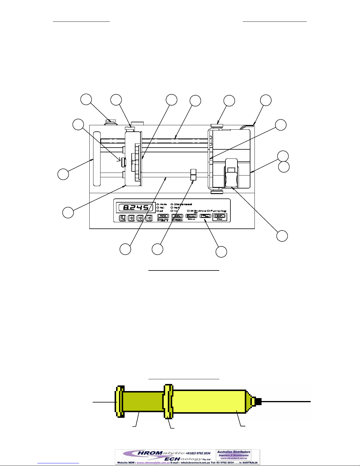
Parts of the Pump
Parts of the PumpParts of the Pump
Parts of the Pump
1) Pusher Block
2) End Plate
3) Anti-Siphon Plate Adjustment Knob
4) Power On/Off Switch
5) Drive-Nut Button
6) Anti-Siphon Plate
7) Drive-Screw
8) Syringe Retainer Thumbscrew (2, one on each side)
9) Hex Wrench (in tool holder)
10) Syringe Retainer Bracket
11) Syringe Holder Block
12) ‘V’ Slot (on Syringe Holder Block)
13) Syringe Clamp
14) Keypad / User Interface
15) Guide Rod Collar Clamp
16) Guide Rod (2 guide rods)
Parts of a Syringe
Parts of a SyringeParts of a Syringe
Parts of a Syringe
Plunger
Flange
Plunger
Barrel
Barrel Flange
8
8 (of 55 )

New Era Pump Systems Inc. www.SyringePump.com Model NE-1000 Multi-Phaser™
Publication #1200-01 404/06/16
Terminology
TerminologyTerminology
Terminology
Momentary Press:
A quick press, less then 1 second, then release of a key on the keypad.
Display Blink:
A momentary blanking of the LCD display. This indicates that the new data
entered by the user is valid and has been stored.
Program Entry
Mode:
The mode where the Program Phase and Program function are selected and
modified. In this mode the ‘Program Phase #’ and the ‘Program Function’
modes of the ‘Rate’ and ‘Volume’ keys are relevant.
Pumping Program:
The sequence of automated operations entered into the pump. This could be as
simple as a single function to pump at a single infusion rate continuously.
Pumping Program
Operating:
When the pump is started with the ‘Start’/’Stop’ key, or any other source, the
pump begins performing the operations in the Pumping Program until the
Pumping Program either stops automatically or the pump is stopped when the
‘Start/Stop’ key is pressed, or from any other source. While performing the
operations defined in the Pumping Program, the Pumping Program is referred to
as operating.
While Operating, the motor can be pumping or stopped, according to the
Pumping Program.
Pumping Program
Stopped:
The motor is stopped and the pump is not operating the Pumping Program.
Pumping Program
Paused:
The Pumping Program has been stopped, but can be resumed at the point where
it was stopped.
Pumping Program
Resumed:
Continuing a Pumping Program that was Paused before the completion of the
Pumping Program. The Pumping Program continues at the point where the
Pumping Program was stopped.
Executed:
The pump has performed a single operational Phase as defined in the Pumping
Program.
Program Phase:
A single defined operation in the Pumping Program.
Phase umber:
A Program Phase’s numerical sequence location in the Pumping Program.
Currently Selected
Function:
Each Pumping Program Phase instructs the pump to perform a particular
operation. Only one Program Phase is selected at any one time. This is the
current Phase. Each Phase is set to one function. The set function of the current
Phase is the currently selected function.
Pumping Rate
Function:
Each Pumping Program function instructs the pump to perform a particular
operation. If the Phase’s operation instructs the NE-1000 to pump, then
associated with that Phase is the Phases’ pumping information. When ‘Program
Entry Mode’ is exited, the ‘Rate’, ‘Volume’, and pumping direction keys refer
to the currently selected Program Phase’s function. The Program functions that
are associated with pumping information are referred to as Pumping Rate
functions.
Function
Parameter:
Certain functions, which do not instruct the NE-1000 to pump, require
additional data. This additional data, displayed with the function, is the
function’s parameter.
Start Trigger:
The Pumping Program may be started, or stopped, from multiple sources.
These are the keypad’s ‘Start’/’Stop’ key, the TTL I/O ‘Operational Trigger’
input, or from a command received through the RS-232 connection.
9
9 (of 55 )

New Era Pump Systems Inc. www.SyringePump.com Model NE-1000 Multi-Phaser™
Publication #1200-01 504/06/16
3. Setup
♦Place the pump on a stable surface.
♦Plug the round connector end of the supplied power supply adapter into the power plug located on the
lower right of the pump's rear. See section 11, Logic Interface: TTL Input and Output, for a diagram of
the rear of the pump. Plug the other end of the power supply adapter into an appropriate electrical outlet.
The pump will be powered when the bottom of the power switch, located on the upper right of the rear of
the pump, labeled ‘1’, is pressed. The red indicator on the switch is visible when the power switch is in
the ‘on’ position. After power is applied to the pump, the pump’s display will flash.
♦Next the Pumping Program can be entered. Before the Pumping Program can be operated, the pump
needs the measurement of the inside diameter, in millimeters, of the syringe that will be loaded. The
syringe diameter can be entered using the keypad on the front panel of the pump.
♦Finally, the syringe can be loaded and the pump started.
4. Loading Syringes
The syringe is loaded by securing the barrel and the pusher flange as follows:
1: Loosen the 2 thumbscrews on the syringe retainer bracket.
2: Press in fully the white drive-nut button on the pusher block, releasing the block. Taking care not to
drag the drive-nut on the drive-screw, slide the block away from the syringe holder, providing sufficient
space for the loaded syringe. Then release the white button.
3: Lift the syringe clamp above the syringe holder block. Turn it 1/4 turn and then lower it onto the
syringe holder block. The syringe clamp should be out of the ‘V’ slot.
4: Load the syringe with the barrel over the syringe holder and the syringe plunger towards the middle of
the pump. Place the barrel on the syringe holder block, in the ‘V’ slot, with the barrel flange inserted
between the syringe holder block and syringe retainer bracket.
5: On the pusher block, turn the thumbscrew to make the slot large enough for the plunger flange. Press in
fully the white drive-nut button on the pusher block, releasing the pusher block. Then slide the block
towards the syringe plunger. Place the syringe plunger flange into the slot and against the anti-siphon
plate. When the flange is positioned in the slot, release the white drive-nut button.
6: Lift the syringe clamp to slightly above the height of the syringe barrel and turn the syringe clamp 1/4 turn
back to its original position and then lower it onto the syringe barrel.
7: Firmly push in the syringe retainer bracket against the syringe barrel flange and tighten the 2 thumbscrews
on the syringe retainer bracket. On the pusher block, turn the thumbscrew to move the plate against the
plunger flange.
⇒To unload the syringe, reverse the instructions for syringe loading.
5. Guide Rod Collar Clamp (Model NE-1000 only)
WARNING: Do not use the collar clamp as a normal method of stopping the pump. This will cause damage
to the drive nut. Pump Stall is a fault condition and not a normal method of stopping the pump.
To protect a fragile syringe from damage caused by over infusion, use the collar clamp to limit the travel of the
pusher block. Using the hex wrench located in the tool holder on the rear of the syringe holder, loosen, but do
not remove, the hex screw on the guide rod collar clamp, enabling the collar clamp to slide on the guide rod.
Position the collar clamp as required, and then tighten the hex screw on the collar clamp with the hex wrench.
Replace the hex wrench in the tool holder. When the pusher block comes in contact with the collar clamp
while infusing, a stall alarm will occur. The pump motor will be stopped and the Pumping Program will be
paused. If alarms are enabled, the buzzer will sound.
10
10 (of 55 )
New Era Pump Systems Inc. www.SyringePump.com Model NE-1000 Multi-Phaser™
Publication #1200-01 604/06/16
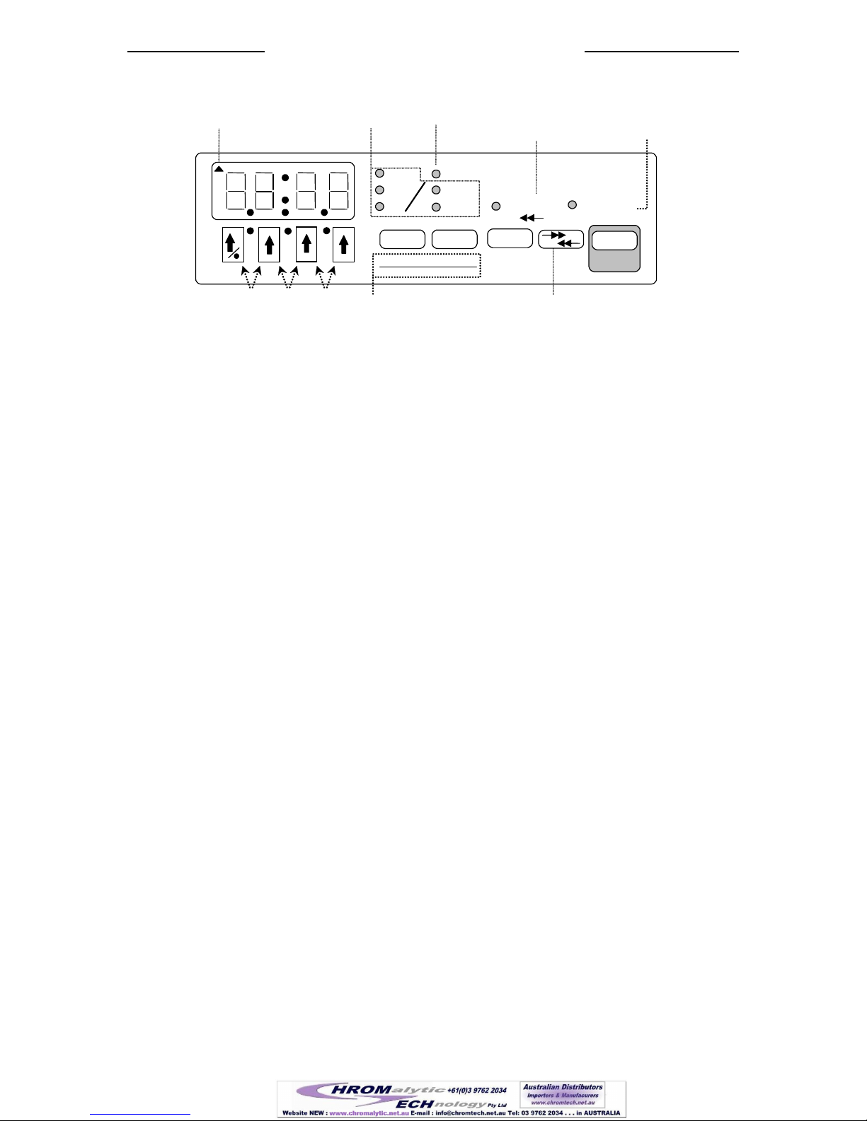
6. User Interface
mm
Volume
Dispensed
mL
Withdraw
min
hr
Pumping
Rate
Volume
Diameter
Start
Pumping Program
Phase #
Function
Setup
µ
L
RS-232
Indicator Units
Indicators
Pumping Direction
Indicator
Volume Dispensed
Indicator
Stop
Motor
Operating
Program Entry Keys
Pumping Direction Key
Syringe ID
Decimal Point: Press 2 keys
Figure 1: Front Panel
6.1 Entering Values
When applicable, values can be changed by either displaying the current value, then using the arrow keys, or
from a computer connected to the pump. The new value will be stored in the pump’s non-volatile memory,
meaning that the new value will not be lost the next time that power is applied to the pump. The only
exception is when the pumping rate is changed from an attached computer while the Pumping Program is
operating. In this case the new pumping rate will not be stored in non-volatile memory.
A displayed value can be changed by pressing the arrow keys below each digit. If the value to be changed is
not currently displayed, when applicable, momentarily press the key associated with the required value. The
display will show the setting’s current value and its units, if any.
While the current value is being changed, the units LEDs associated with the value, if any, will blink. Except
where noted, the new value is stored, and/or the selected operation takes effect, when either
1) A non-arrow key is pressed or
2) After a 2 second delay since the last arrow key was pressed.
If the new value is valid and different from the original value, the display will blink, indicating that the new
value was stored. Otherwise, if the value was invalid, an error message will be displayed. Pressing any key
clears the error message and restores the original value.
In general, if a parameter has 2 values, ‘off’ and ‘on’, they are represented by the numbers ‘0’ and ‘1’,
respectfully.
6.2 LCD Display
The display consists of a 4 digit reflective LCD (Liquid Crystal Diode) display. This is the general purpose
user display device for displaying numerical data, functions and parameters. The colon (:) is used for
displaying time or for separating function abbreviations from their parameter values. In the upper left corner is
a triangle that indicates valid reception of RS-232 remote communications.
6.3 LEDs
To the right of the LCD are 8 red, round, LED (Light Emitting Diode) indicators. The first 2 columns display
the units of the displayed values. Units are expressed using 1 or 2 LEDs. For instance, ‘mL / hr’ is expressed
by lighting the ‘mL’ and the ‘hr’ LEDs.
‘Dispensed’ indicates that the displayed volume is the total ‘Volume Dispensed’ or pumped.
When ‘Pumping’ is lit (not blinking), the motor is operating, either infusing or withdrawing. If blinking, the
motor is not operating, and the Pumping Program is paused. When the pump is restarted, the Pumping
Program will resume at the point where the Pumping Program was interrupted. When not lit (not blinking) the
pump is stopped, but the Pumping Program may be operating a pause Phase. Starting the pump, when the
Pumping Program is stopped, will start the Pumping Program from the beginning (Phase 1).
‘Withdraw’ indicates that the pumping direction is set for withdrawing. If not lit, then the pumping direction
is set for infusing. When blinking, “Sticky Direction” is set. Also, the ‘Withdraw’ LED indicates that the
11
11 (of 55 )
New Era Pump Systems Inc. www.SyringePump.com Model NE-1000 Multi-Phaser™
Publication #1200-01 704/06/16
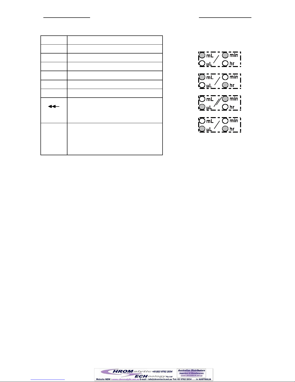
Pumping rate units are expr
essed using 2 LEDs:
‘mL/min’ =
‘mL/hr’ =
‘µL/min’ =
‘µL/hr’ =
“Volume Dispensed” refers to the volume withdrawn. If not lit, the “Volume Dispensed” refers to the volume
infused.
6.4 Arrow and Decimal Point Keys
Each of the four digits in the display is associated with the up arrow key directly below it. When applicable,
the arrow key is used to increment the value of that digit, or advance to the next selection in a list of functions
or settings.
Each press of an up arrow key will increase the digit by 1, up to 9, and then back to 0. The arrow keys may
also be held down for continuous incrementing of numbers. Some parameters, such as the RS-232 baud rate,
scroll through a selection of values when the arrow keys are pressed. Other parameters have a fixed range of
values, such as some setup parameters that are either turned on or off. In these cases, the arrow key will only
scroll up to the maximum value for that parameter, then back to the minimum value.
When changing the pumping rate units, each press of any arrow key will change the units LEDs to the next
units selection.
When the display blinks, the new value is stored and takes effect. This will occur when a non-arrow key is
pressed or after a 2 second delay since the last key press.
6.4.1 Decimal Point
There are 4 decimal point positions on the LCD display. Each decimal point position is to the right of a digit
in the display. The last decimal point position, to the right of the right-most digit is not displayed, indicating
whole numbers with no decimal point.
To move the decimal point, simultaneously press the 2 up arrow keys under the 2 digits next to the decimal
point position. Press the same 2 up arrow keys to clear the decimal point, to display a whole number.
Alternatively, to move the decimal point position, use the left-most arrow / decimal point key (/). Press
and hold this key for at least 1 second and wait until the left-most digit scrolls past ‘9’ to ‘0’. While
continuing to hold this key, the decimal point will shift 1 position to the right. After the right-most decimal
point position, the decimal point will shift to the first decimal point position. Release the key when the
decimal point is in the required position.
6.5 ‘Diameter’ and ‘Setup’ Key
The ‘Diameter’ key allows the syringe inside diameter to be viewed and set. While being displayed, the ‘mm’
LED is lit. Momentarily pressing this key will display the current diameter setting. With the Pumping
Program stopped , pressing the up arrow keys will change the current diameter (see sec.6.4,
LED Description
mm Millimeters
mL Milliliters
min Minutes
µ
L Microliters
hr Hours
Dispensed Volume dispensed displayed
Withdraw
Pumping Direction:
Lit: Withdraw
Not lit: Infuse
Blinking: “Sticky Direction”
Pumping Lit: Motor is operating
Not lit: The Pumping Program is stopped
or executing a Pause Function
Blinking: The Pumping Program is paused
12
12 (of 55 )

New Era Pump Systems Inc. www.SyringePump.com Model NE-1000 Multi-Phaser™
Publication #1200-01 804/06/16
Arrow and Decimal Point Key). The ‘mm’ LED will blink while the diameter is being changed.
If the ‘Diameter’ key is pressed and held, ‘Setup’ mode will be entered. (See sec. 6.12, ‘Setup’ ).
6.6 ‘Rate’ and ‘Program Phase #’ Key
When the Pumping Program is stopped, except in “Program Entry Mode”, the ‘Rate’ key allows the pumping
rate to be viewed or changed. If the currently selected function allows selection of rate units, momentarily
pressing this key will switch between the ‘Rate’ display and the select rate units mode.
To change the pumping rate displayed, use the up arrow keys (see sec.6.4,
Arrow and Decimal Point Key).
While the Pumping Program is operating, pressing this key will display the current pumping rate, if applicable.
While displayed, the current pumping rate can be changed by pressing the up arrow keys. The rate units will
blink while the rate is being changed. The new pumping rate takes effect when the display blinks after a 2
second delay or when a non-arrow key is pressed. The new pumping rate is stored in the current Program
Phase.
See section 12.7, “Syringe Diameters and Rate Limits”, for a list of minimum and maximum pumping rates. A
pumping rate of 0.0 will stop the pump. When the pumping rate is changed, if it is out of range of the pumping
rate limits, the display will show
nn
, where ‘nn’ indicates the currently selected Phase Number.
Pressing any key clears the message and returns to the previous pumping rate.
6.6.1 Pumping Rate Units
The pumping rate units can only be changed when the Pumping Program is not operating. If the currently
selected function allows selection of rate units (‘RATE’ function), a momentary press of the ‘Rate’ key will
enter Rate Units Change mode. The 2 LEDs representing the units will blink and the display will show:
.
Each press of any up arrow key selects the next rate units, as indicated by the blinking units LEDs. When the
required rate units are blinking, press any non-arrow key or wait 2 seconds. The display will blink, indicating
the rate units are stored. The rate units are stored in the currently selected Program Phase. The rate units can
be independently set for each Phase with a ‘RATE’ function.
6.6.2 Program Entry Mode
While the Pumping Program is stopped, “Program Entry Mode” can be entered by pressing and holding the
‘Rate’ key. Release the key when the display shows the current Program Phase number:
nn
, where
‘nn’ indicates the current Program Phase number.
With the current Program Phase number displayed, if the currently selected Program Phase is set to a pumping
rate function, a momentary press of this key will exit “Program Entry Mode” and return to the rate display.
6.7 ‘Volume’ and ‘Program Function’ Key
When the Pumping Program is stopped, except in “Program Entry Mode”, momentary presses of this key will
switch the display between the “Volume to be Dispensed” and the “Volume Dispensed” displays, as indicted
by the ‘Dispensed’ LED.
With the Pumping Program stopped, and the “Volume to be Dispensed” displayed, pressing the arrow keys
will change the “Volume to be Dispensed” (see sec.6.4,
Arrow and Decimal Point Key). The units of the volume are set according to the syringe diameter, but can be
changed. The new “Volume to be Dispensed” is stored in the current Program Phase. If the “Volume to be
Dispensed” is disabled (‘off’), pressing any up arrow key will change the display to 0.0. The “Volume to be
Dispensed” can now be set using the up arrow keys.
While pumping, pressing this key will switch between displaying the current “Volume Dispensed” and
“Volume to be Dispensed”.
6.7.1 Disabling “Volume to be Dispensed”
13
13 (of 55 )

New Era Pump Systems Inc. www.SyringePump.com Model NE-1000 Multi-Phaser™
Publication #1200-01 904/06/16
To disable the “Volume to be Dispensed”, i.e. continuous pumping, set the “Volume to be Dispensed” to 0.0.
After being stored, the display will show , indicating the “Volume to be Dispensed” is off. In this
mode, the pump will not stop at a set volume and will pump continuously until the pump is stopped, or an
“event trigger”, programmed into the Pumping Program, occurs.
6.7.2 Clearing “Volume Dispensed”
With the Pumping Program stopped, display the “Volume Dispensed”. Pressing and holding any up arrow key
for one second will reset the infusion and withdrawal dispensed volumes to 0.
6.7.3 Program Entry Mode
“Program Entry Mode” is entered by pressing and holding the ‘Volume’ key. Release the key when the
display shows the currently selected Program Phase’s function.
In “Program Entry Mode”, when the Program Function is not displayed, momentarily pressing this key will
display the current Program Function.
When the Program Function is displayed, if the function is a pumping rate function, “Program Entry Mode”
can be exited by momentarily pressing the ‘Volume’ key. The display will show the “Volume to be
Dispensed”.
Otherwise, pressing the ‘Volume’ key will display the “Volume Dispensed”. Pressing the ‘Volume’ key again
will return to displaying the Program Function.
6.8 Pumping Direction Key
The pumping direction key, ‘ ’, changes the direction of pumping. Pressing this key switches the
pumping direction between ‘infuse’ and ‘withdraw’, as indicated by the ‘Withdraw’ LED. When the LED is
lit, the pumping direction is ‘withdraw’, not-lit, pumping direction is ‘infuse’, blinking indicates “Sticky
Direction” is set. The new pumping direction is stored in the current Program Phase.
The “Volume Dispensed” is accumulated separately for infusion and withdrawal. When the pumping direction
is changed, the current “Volume Dispensed” is also changed accordingly between the infusion and withdrawal
“Volume Dispensed” accumulations.
When the Pumping Program is operating and the “Volume to be Dispensed” is non-zero, the pumping
direction cannot be changed. Otherwise, when pumping continuously (“Volume to be Dispensed” disabled),
the pumping direction can be changed.
6.8.1 Sticky Direction
With the pump stopped, press and hold the direction key to set “Sticky Direction”. The LED will blink when
set.
“Sticky Direction” will continue the pumping direction of the previous Pumping Phase or, if the first Phase, set
the pumping direction according to the logic level of the “Pumping Direction” TTL input pin (pin 3):
Direction Control: Reciprocating Pumps (dr:rE) Dual Pumps (dr:dU)
Low Level: Infuse Withdraw
High Level: Withdraw Infuse
6.9 ‘Start’/’Stop’ Key
The ‘Start/Stop’ key starts or stops the Pumping Program’s operation. Pressing this key switches between the
Pumping Program operating and the Pumping Program paused. When the ‘Start/Stop’ key is pressed before
the completion of a Program, the motor is stopped and the Pumping Program will be paused. The ‘Pumping’
LED will then blink, indicating that the Pumping Program is paused.
Pressing this key again will resume the Program at the point it was paused. If any other key is pressed while
the Pumping Program is paused, the Pumping Program will be stopped and reset. Pressing the ‘Start/Stop’ key
will then start the Pumping Program from the beginning (Phase 1).
Pressing and holding this key while starting the Pumping Program will start the purge mode. Purge will begin
after the key is held for one second, and continue until the key is released. The pump will stop after the key is
released.
“Button Trigger Event Trap” Program Function redirects ‘Stop’ key to a Program Event.
14
14 (of 55 )
New Era Pump Systems Inc. www.SyringePump.com Model NE-1000 Multi-Phaser™
Publication #1200-01 10 04/06/16
6.10 ‘Program Phase #’ (Number) Key
When in the “Program Entry Mode”, momentary presses of the ’Program Phase #’ and the ‘Program Function’
keys switch between the Program Phase number and the Program Function displays. The Program Phase
number will be displayed as
nn
, where ‘nn’ is the current Program Phase number.
When the Program Phase number is displayed and the current Phase’s function is a rate function, a momentary
press of the ‘Program Phase #’ key exits ‘Program Entry Mode, and displays the pumping rate.
To change the current Program Phase number, press the arrow keys below the Phase number’s digits. The
maximum Phase number is 41. To reset to Phase number 1, press and hold the ‘Program Phase #’ key until the
Phase number is 1.
When a new Program Phase number is selected, the current value of all settings will be that of the currently
selected Program Phase.
6.11 ‘Program Function’ Key
When in the “Program Entry Mode”, momentary presses of the ’Program Phase #’ and the ‘Program Function’
keys switch between the Program Phase number and the Program Function displays.
With the Program Phase function displayed, the Program Function can be selected. Pressing any arrow key, or
an arrow key to the left of the colon (:) or decimal point (.) if displayed with the function, will select the next
Program Function. The selected function is stored by either pressing any non-arrow key, or after a 2 second
delay. If the selected function is different from the original function, the display will blink when the selected
function is stored.
6.11.1 Program Phase Function Parameter
If the selected function has a parameter associated with the function, the value of the parameter will be
displayed to the right of the function name, separated by either a period (.) or a colon (:).
To change the parameter’s value, press the arrow keys below the parameter’s digits. The parameter’s new
value is stored by either pressing any non-arrow key or after a 2 second delay. If the parameter has changed
from its original value, the display will blink when the parameter’s new value is stored.
6.12 ‘Setup’ Key
The secondary function of the ‘Diameter’ key is ‘Setup’. While the Pumping Program is not operating, press
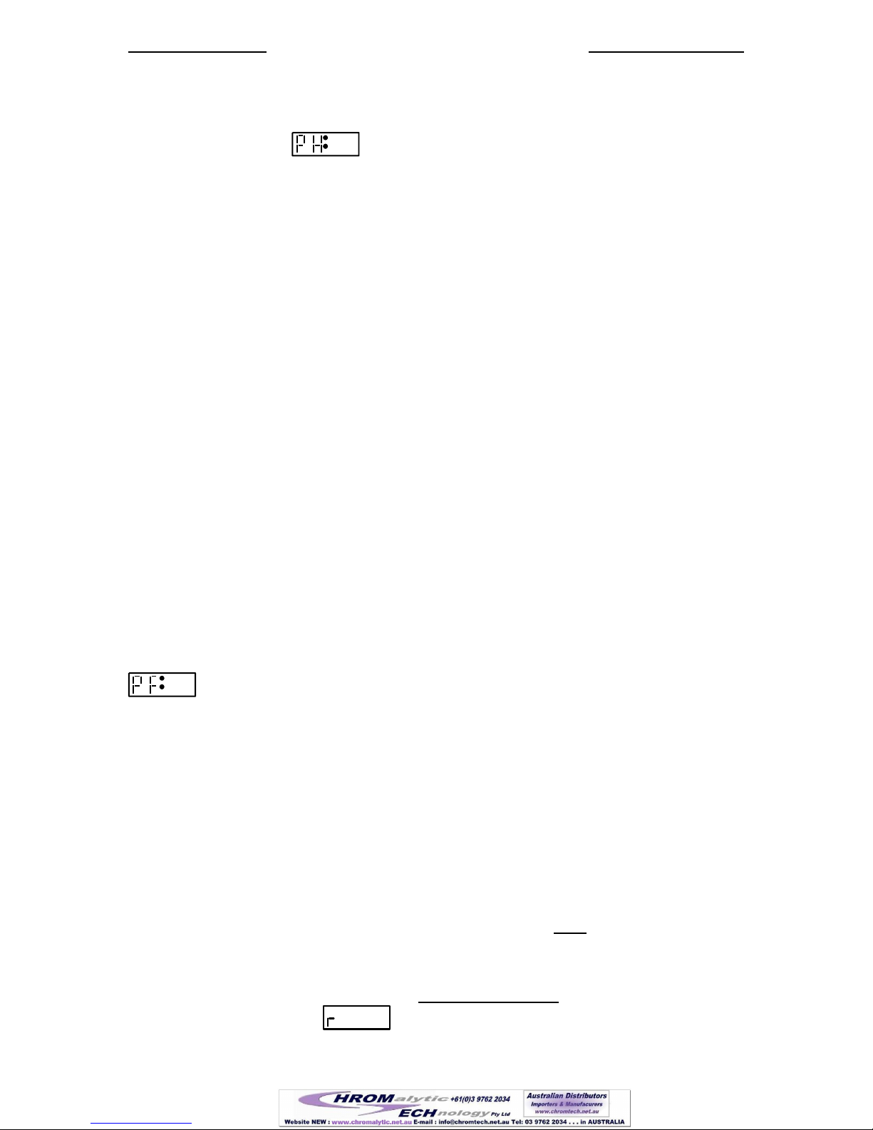
and hold the ‘Diameter’ key until the first setup configuration parameter, “Power Failure Mode”, is displayed:
n
.
The display will consecutively display, for about 2 seconds, each Setup Configuration parameter and its
current setting. Pressing any non-arrow key will immediately advance to the next Setup Configuration
parameter.
To change a Setup Configuration parameter, press an arrow key under the parameter’s value. To store the new
value, press any non-arrow key or wait 2 seconds. If the parameter value differs from its previous value, the
display will blink. The new parameter value will be stored and the next parameter will be displayed. See
section 8, “Setup Configuration” for a complete description of the Setup Configurations.
After the last configuration parameter is displayed, the display reverts back to displaying the syringe diameter.
Any new parameter value will take effect immediately upon being stored.
6.13 Special Power-Up Functions
The following special functions are accessed by pressing the relevant key, while turning on power to the
pump.
6.13.1 Firmware Version Display
To display the pump’s firmware version, press the left-most up-arrow key (/) while turning on power to
the pump. The display will show:
n.nn
, where ‘n.nn’ is the firmware version number. Pressing any key
will clear the display.
15
15 (of 55 )

New Era Pump Systems Inc. www.SyringePump.com Model NE-1000 Multi-Phaser™
Publication #1200-01 11 04/06/16
6.13.2 Reset Pumping Program
To clear out the current Program Function setups, press the right-most up-arrow key () while turning on
power to the pump. The display will show . Pressing any key will clear the display.
With a pump with as many complex features as the NE-1000, it is easy for a novice user experimenting with
the pump's setup to get the pump into a 'weird' state. Performing this reset function will bring the pump out of
a 'weird' state.
6.13.3 Default Program Pre-Load
Pressing the 'Volume'/'Program Function' key while turning on power to the pump will display the Default
Program Menu and the display will show the first default program: , Reciprocating Pumping
program. Us the up arrow keys to select the next program. When the Reciprocating Pumping program is
selected, the following program will be loaded and stored in the Pumping Program memory, plus the RS-232
communications mode will be set to Reciprocating Mode. The default program will over write any other
program stored in memory and it can then be modified as needed.
The Reciprocating Pumping Program, plus cable Part# CBL-DUAL-3, sets the pump for use with a second
pump to create a continuous infusion system.
Phase Function Rate Volume Direction
1 RATE 500 mL/hr 10.0 mL Withdraw
Phase Function Rate Volume Direction
2 FILL 0.0 mL/hr ----------- ------------
Phase Function
3 JP:01
6.13.4 Program Entry Mode Lockout
Pressing the ‘Diameter’ key while turning on power to the pump will enter special parameter setup. The
following will be displayed:
n
, currently, the only parameter. The “Program Entry Mode Lockout”,
when enabled, prevents inexperienced users from entering “Program Entry Mode” from the keypad. Mode
Disabled: ‘n’ = 0 (default). Mode Enabled: ‘n’ = 1. When enabled, only Phase 1 ‘Rate’, ‘Volume’ and
Pumping Direction can be changed. Cannot be enabled when the Pumping Program is currently programmed
with a multiple Phase Program.
6.14 Error and Alarm Messages
If the value entered is beyond the pump's capabilities or is invalid, or an operational problem occurred, one of
the following error or alarm messages will be displayed:
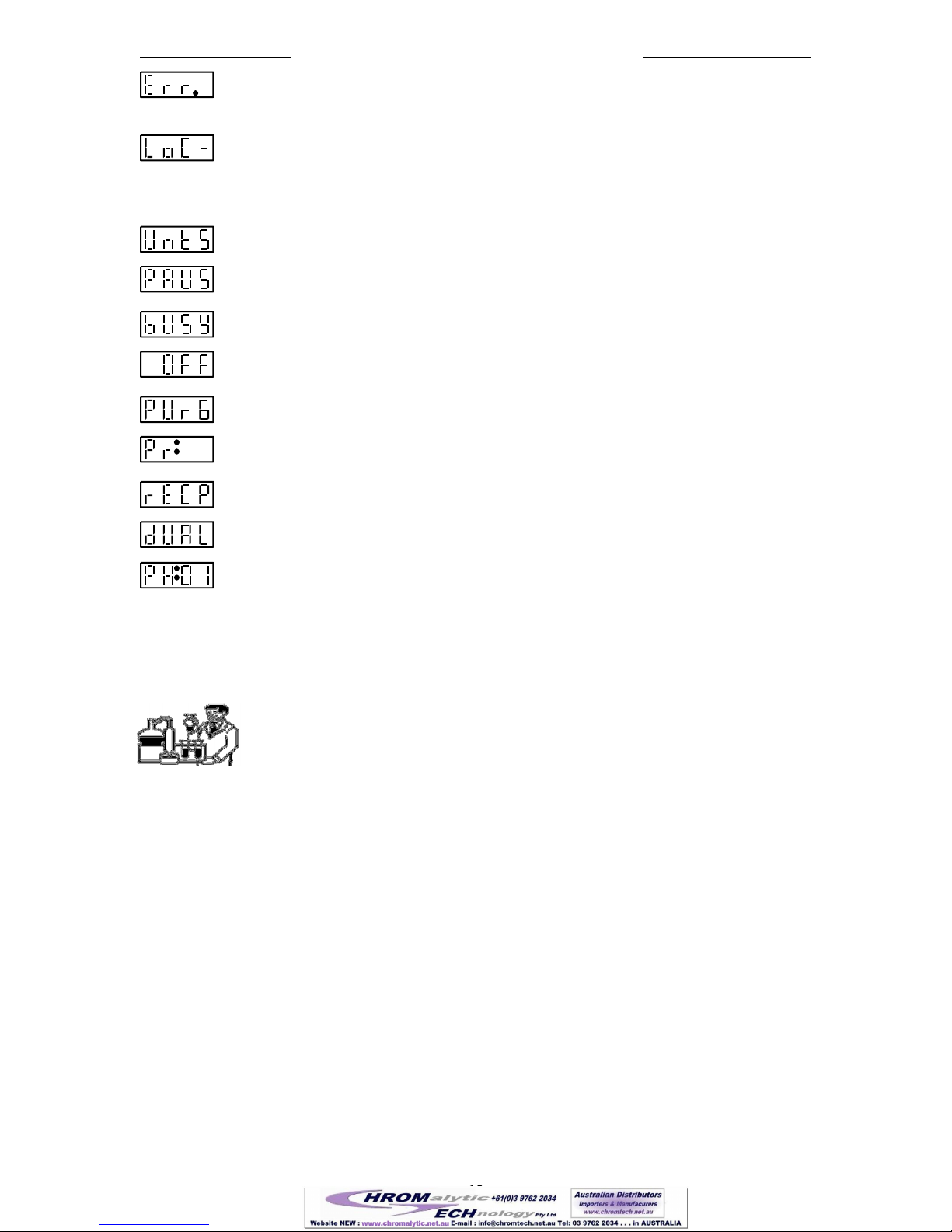
Pump motor stalled alarm.
Value entered is ‘Out Of Range’ of the pump’s operational limits.
nn
An out of range error occurred at Pumping Program Phase number ‘nn’, or the value just
entered is out of range. Check the pumping parameters and syringe diameter.
nn
A Pumping Program error was encountered at Pumping Program Phase number ‘nn’.
The indicated Phase is invalid in the context of the entire Pumping Program.
Key pressed is not currently applicable.
A communications time-out alarm occurred with an attached computer while operating in
the “Safe Communications Mode”. This most likely indicates that the RS-232 cable was
detached or the communication program on the computer has ended without turning off
“Safe Communications Mode”.
16
16 (of 55 )
New Era Pump Systems Inc. www.SyringePump.com Model NE-1000 Multi-Phaser™
Publication #1200-01 12 04/06/16
n
An error was detected during power up, where ‘n’ indicates the error. If n=1, then the
values stored in the pump’s non-volatile memory were invalid and were reset. If n=2,
then the non-volatile memory may need to be replaced.
Pump settings are locked out from the keypad. The lockout key is needed to change
settings. Lockout can also be reset with the reset function.
6.15 Status Messages
Indicates pumping rate units change mode. The units LED's will also be blinking.
Indicates that the Pumping Program has paused and is waiting for the user to press
‘Start’, or for an external operational trigger, to continue.
Indicates that the pump is busy completing a long operation.
Indicates that the “Volume to be Dispensed” is 0.00, and is turned off. This is the
continuous pumping mode.
Indicates that the pump is purging. Displayed while holding down the 'Start/Stop' key.
nn
Indicates that the Pumping Program paused and is waiting for the user to select a sub-
program.
Indicates that the pump’s RS-232 communications is set for either Reciprocating or Dual
pumping modes. One of these messages will be briefly displayed while the pump is
searching for the secondary pump. Normally, seeing one of these messages would
indicate that the secondary pump is not attached or communication cannot be established.
Indicates that the Pumping Program entry mode has been entered, possibly after the
‘Rate’ key was pressed and held. A momentary press of the ‘Rate’ key will return the
display to the pumping rate. This display may also indicate that the first Pumping
Program Phase is not a ‘Rate’ function.
7. Operation
Before the pump can be operated, the pumping data must be setup. At minimum, the
syringe inside diameter and a non-zero pumping rate needs to be set. The operation of the
pump can then be started from the keypad, TTL I/O connector, or from RS-232 control.
From the keypad, pressing the ‘Start / Stop’ key will start the pump operation.
7.1 Syringe Inside Diameter
The syringe inside diameter can only be set while the Pumping Program is stopped. Use the up arrow keys to
set the diameter value. While the diameter value is being set, the ‘mm’ LED will blink. The new diameter
value is stored after pressing any non-arrow key, or after a 2 second delay.
Valid syringe diameters are from 0.1 mm to 50.0 mm. If the diameter is out of this range, the display will
show ‘oor’. Pressing any key restores the diameter display to its previous value. Changing the syringe
diameter will not zero any current settings. Section 12.7, “Syringe Diameters and Rate Limits”, is a
representative list, for reference, of syringe diameters for various syringe manufacturers and syringe sizes.
7.1.1 Default Volume Units
The units of the accumulated infusion and withdrawal volumes and the “Volume to be Dispensed” are set
according to the diameter setting. NOTE: A change in the volume units will affect all “Volume to be
Dispensed” settings in the Pumping Program. If the default volume units are changed (see next section), the
selected volume units will remain in effect until a reset function is performed.
From 0.1 to 14.0 mm Syringes smaller than 10 mL: Volume units are ‘µL’
From 14.01 to 50.0 mm Syringes greater than or equal to 10 mL: Volume units are ‘mL’
17
17 (of 55 )

New Era Pump Systems Inc. www.SyringePump.com Model NE-1000 Multi-Phaser™
Publication #1200-01 13 04/06/16
7.1.2 Changing Volume Units
The Volume Units used for accumulated volumes and the “Volume to be Dispensed” settings can be changed
to either ‘mL’ or ‘µL’. Volume Units can only be changed while the Pumping Program is stopped. A change
in the Volume Units will affect all “Volume to be Dispensed” settings in the Pumping Program.
To change the Volume Units, display the “Volume Dispensed” by pressing the “Volume” key once or twice.
The current Volume Units and the “Dispensed” LED will be lit.
Set the Volume Dispensed to 0.000 if it is not zero: Press and hold any up arrow key until the Volume
Dispensed is set to 0.000.
Now, pressing any up arrow key will change the display to and the current Volume Units will
blink.
Then, press any up arrow key to switch the Volume Units between ‘mL’ and ‘µL’. Press any non-arrow key or
wait 2 seconds to enter the new Volume Units. The display will blink when entered. The selected Volume
Units will remain in affect and override the default Volume Units. Changing the diameter will no longer
change the Volume Units. Performming a system reset will cancel the override and allow the Volume Units to
change to the default Volume Units when setting the syringe diameter.
7.2 Start/Stop Triggers
The Pumping Program can be started or stopped from three sources: The keypad ‘Start/Stop’ key, RS-232
‘RUN’ command, or the TTL I/O Operational Trigger input. Each can control the Pumping Program’s
operation.
7.3 Operating the Pump
When the “Start/Stop” key is pressed, the Pumping Program begins to operate, starting with Phase 1. If the
current Program Phase specifies a pumping rate, the pump will begin pumping, and the ‘Pumping’ LED will
be lit. The pumping direction will depend on the Phase setup.
While pumping, the pump will pump continuously in the current Program Phase, unless a “Volume to be
Dispensed” is set, or an Event trigger is set. If a “Volume to be Dispensed” is set, the Program Phase will be
complete after the set volume has been infused or withdrawn, measured from the start of the Phase.
The display can be changed by pressing the ‘Rate’, ‘Volume’, or ‘Diameter’ keys.
7.4 Purging
To purge the syringe, with the Pumping Program stopped, press and hold the 'Start/Stop' key. The Pumping
Program will start then, after one second, purge will begin. The pump will pump at its top speed in the
currently set direction. Purging will continue until the 'Start/Stop' key is released, and then the pump will stop.
While purging the display will show: .
7.5 Changing the Pumping Rate and Direction While Pumping
Except with some complex Pumping Programs, the pumping rate can be changed while the pump is operating.
To change the pumping rate, display the pumping rate by momentarily pressing the ‘Rate’ key. With the
pumping rate is displayed, press the up arrow keys to change the rate. The rate units will blink while entering
the rate. Rate units cannot be changed while pumping.
The new rate is stored after a 2 second delay or by pressing a non-arrow key. If the new rate is within the
operating range of the pump, the display will blink and the new rate will be stored in the current Program
Phase and the pump will begin to pump at the new rate. If the new rate is out of the operating range of the
pump, the display will show
nn
. Pressing any key clears the error message.
The pumping direction can be changed while pumping if the “Volume to be Dispensed” is 0.0 (off). Pressing
the direction key will immediately change the pumping direction and store the pumping direction in the current
Program Phase. Also changing the pumping direction changes the accumulated “Volume Dispensed”
according to the new pumping direction.
7.6 Volume Dispensed
When the total accumulated volume pumped is displayed, the ‘ml’ or ‘µl’ LED is lit and the ‘Dispensed’ LED
is lit. Volume is computed based upon the syringe inside diameter setting. The accumulated Volume
18
18 (of 55 )
New Era Pump Systems Inc. www.SyringePump.com Model NE-1000 Multi-Phaser™
Publication #1200-01 14 04/06/16
Dispensed can be displayed by pressing the ‘Volume’ key one, two, or three times, depending on the current
display.
The volume is accumulated separately for infusion and withdrawal. When the pump changes direction, the
“Volume Dispensed” changes to the accumulated volume for the current pumping direction.
The “Volume Dispensed” accumulations for infusion and withdrawal are reset to 0 when:
A) With the pump stopped, pressing and holding any up arrow key while displaying the “Volume
Dispensed”.
B) A sub-program is selected when the Pumping Program executes a Program Selection function.
C) The syringe diameter is changed.
D) From the RS-232 clear “Volume Dispensed” command (CLD) or Clear Dispense function.
E) The accumulated Volume Dispensed rolls over from 9999 to 0.
F) The pump is powered on.
7.7 Resuming When Paused
If the Pumping Program is stopped before the completion of the Pumping Program, the ‘Pumping’ LED will
blink, indicating that the Pumping Program is paused. While the ‘Pumping’ LED is blinking, starting the
pump again will resume the Pumping Program where it was stopped. This means that the Pumping Program
will continue at the point in the Phase where it was stopped and the ‘Volume to be Dispensed’ will still be
referenced from when the Program Phase first started.
Pressing any key other than the ‘Start’ key will cancel “Pumping Program paused” and the ‘Pumping’ LED
will stop blinking. When the Pumping Program is started again, it will start from the beginning (Phase 1).
7.8 Pump Stalled
WARNING: Do not use Stall as a normal method of stopping the pump. Continuous stalling will cause
damage to the drive nut.
When the operation of the motor is impeded due to excessive force needed to drive the syringe, or when then
collar clamp position is reached, the pump will stop, pausing the Pumping Program, and a stall alarm will
occur. The display will show , the ‘Pumping’ LED will blink, and the buzzer will sound
continuously if alarms are enabled. Also, if the RS-232 Safe Mode is enabled, an auto-alarm message will be
sent to an attached computer.
Pressing any key will stop the buzzer and clear the alarm. When the problem causing the pump motor to stall
has been corrected, the Pumping Program can be resumed from any start trigger source: ‘Start’/’Stop’ key,
TTL input, or RS-232 command.
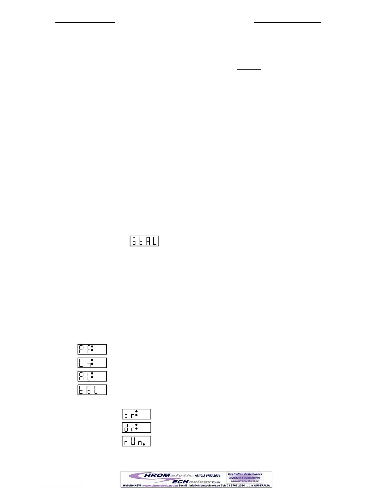
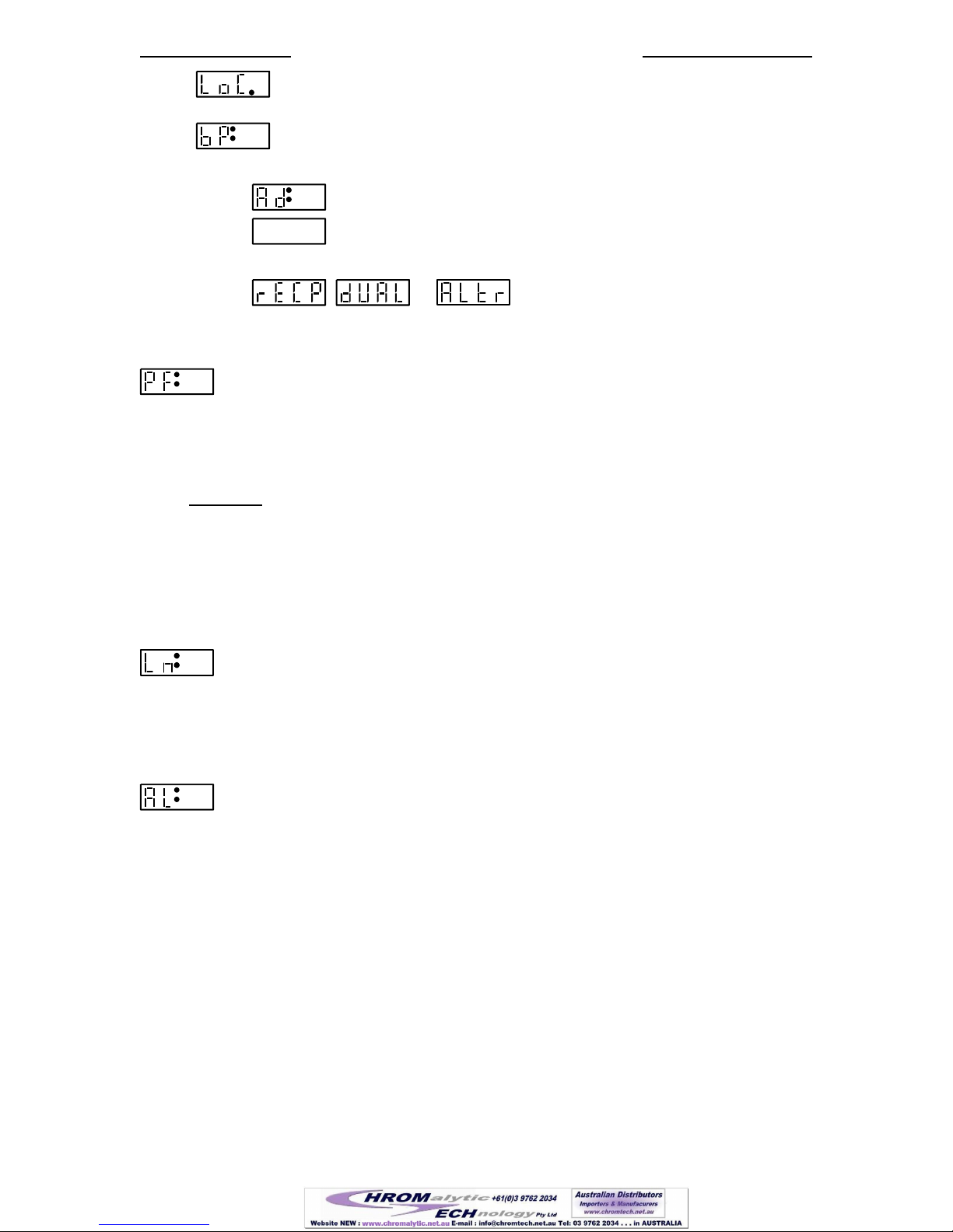
8. Setup Configuration
To change or view the setup configuration, the Pumping Program must be stopped. Press the
‘Diameter’/‘Setup’ key until the first parameter, ‘PF’ is displayed. After 2 seconds, or when any non-arrow
key is pressed, the next parameter will be displayed (see sec. 6.12, ‘Setup’ Key). Pressing an arrow key under
a value will increment, select, or scroll through the valid values for the parameter. The Setup Configurations
will be displayed in the following order:
n
Power Failure mode, where ‘n’ is the current setting.
n
Low Noise mode, whre ‘n’ is the current setting
n
Alarm mode, where ‘n’ is the current setting.
Display TTL I/O external logic connector settings. Press any arrow key to select.
If TTL is selected, the following TTL logic settings will be displayed:
aa
Operational Trigger default setting. ‘aa’ is current setting.
aa
Directional control setting. 'aa' is current setting.
n
'Pump Motor Operating' TTL output pin configuration. 'n' is the
current setting.
19
19 (of 55 )
New Era Pump Systems Inc. www.SyringePump.com Model NE-1000 Multi-Phaser™
Publication #1200-01 15 04/06/16
n
*** The "Lockout Disable Key" needs to be inserted to display this setting. ***
Locks out changing settings from the keypad. 'n' is the current setting.
n
Keypad and notifications beep enable, where ‘n’ is the current setting.
If standard communications mode with a computer is set, then the following are displayed:
nn
RS-232 pump network address, where ‘nn’ is the network address.
nnnn
RS-232 pump network baud rate, where ‘nnnn’ indicates the baud rate.
Otherwise, the current communications mode will be displayed:
, , or
Reciprocating, Dual Pump, or Alternating
Communications Mode.
8.1 Power Failure Mode
n
Setting: ‘0’ = Disabled, ‘1’ = Enabled.
When enabled, if the Pumping Program was operating when power to the pump was disrupted, the Pumping
Program will automatically start operating when power is reconnected to the pump. Pressing any key on the
keypad while powering up the pump will stop the Pumping Program from starting.
CAUTION: The Pumping Program will start operating from the beginning of the Pumping Program
(Phase 1), regardless of what part of the Pumping Program was operating when the power was disrupted.
When the NE-1000 syringe pump is used as a component in an automated infusion/withdrawal dispensing
system, a Pumping Program can be designed to automatically synchronize the pusher block at the start of the
Pumping Program. This would be accomplished using attached sensors that send signals to the Pumping
Program.
8.2 Low Noise Mode
n
Setting: ‘0’ = Disabled, ‘1’ = Enabled.
A side effect of the NE-1000’s high precision micro-stepped motor driver is a high frequency resonance sound
at very low pumping speeds. This mode minimizes this sound by reducing the micro-stepping, increasing
pulsations.
8.3 Audible Alarm Enable
n
Setting: ‘0’ = Disabled, ‘1’ = Enabled.
When alarms are enabled, a steady buzzer alarm will sound during alarm conditions, such as when the motor
stalls: Pressing any key will stop the alarm.
20
20 (of 55 )
Table of contents
Popular Laboratory Equipment manuals by other brands


BioLAB
BioLAB BIFL-207 Operation manual

Hach
Hach 2100Q Basic user manual

IKA
IKA T 25 digital ULTRA-TURRAX operating instructions

Thermo Scientific
Thermo Scientific MaxQ 2000 operating manual

Oxford Instruments
Oxford Instruments Andor iKon-L Hardware guide

Spectra-Physics
Spectra-Physics Pulseo Series user manual