PreeKem TOPEX User manual

Ver 1.0
2
TOPEX service manual
Preface
This manual is aim to guide maintenance engineer to solve instrument faults on spot.
Maintenance engineer need to understand the knowledge of electrical safety and electrical theory,that will
ensure the life safety in the process of maintenance.
Before troubleshooting , maintenance engineer should be familiar with instrument wiring diagram,fully
understand the components’ work voltage and working mechanism.
Please give special attention to the bold part of this manual.
Our company will not be responsible for any losses caused by secretly scrap build.
Please feel free to contact us if you confront problems via E‐mail: support@preekem.com. We will response
your question as soon as possible.

3
目录
Preface....................................................................................................................................................................... 2
1 Introduction.............................................................................................................................................................5
1-1 Summarize......................................................................................................................................................5
1-2 technical parameters.................................................................................................................................... 5
1-3 Safety precautions.........................................................................................................................................5
1-4 Safety standards............................................................................................................................................5
1-5 Application rules............................................................................................................................................ 6
2 Components describe.......................................................................................................................................... 7
2-1 Axonometric views........................................................................................................................................ 7
2-2 Safety door disassemble..............................................................................................................................8
2-3 Bottom view....................................................................................................................................................9
2-4 Main control board layout.......................................................................................................................... 10
3 Commonly used spare parts replacement.....................................................................................................12
3-1 Magnetron replacement.............................................................................................................................13
3-2 Magnetron cooling fan repalcement........................................................................................................13
3-3 HV transformers replacement...................................................................................................................14
3-4 HV capacitor replacement.........................................................................................................................15
3-5 Thyristor replacement.................................................................................................................................16
3-6 Exhaust fan replacement...........................................................................................................................18
3-7 Pressure sensor replacement...................................................................................................................20
3-8 Turntable motor replacement....................................................................................................................21
3-9 LCD replacement........................................................................................................................................ 23
3-10 Built-in camera and monitor replacement............................................................................................ 24
3-11 LED backlight replacement.....................................................................................................................26
3-12 Push style electromagnet replacement................................................................................................ 26
4 Trouble shooting................................................................................................................................................. 27
4-1 HV components measuring method........................................................................................................29
4
TOPEX service manual
4-1-1 Filament transformer...........................................................................................................................30
4-1-2 HV transformer.....................................................................................................................................30
4-1-3 HV capacitor.........................................................................................................................................30
4-1-4 HV diode................................................................................................................................................30
4-1-5 Magnetron.............................................................................................................................................30
4-2 Infrared sensor.............................................................................................................................................31
4-3 Pressure sensor.......................................................................................................................................... 31
5. Fault cause analysis..........................................................................................................................................32
5-1 No microwave generated...........................................................................................................................32
5-2 Garble microwave power match...............................................................................................................32
5-3 Infrared display value error........................................................................................................................32
5-4 Pressure display value error..................................................................................................................... 32
5-5 Other components faults.......................................................................................................................... 32
6 Parameter calibration........................................................................................................................................33
6-1 Temperature calibration (PT100).............................................................................................................33
6-2 Pressure parameter calibration................................................................................................................ 35
7 Wiring diagram.................................................................................................................................................... 35

5
1 Introduction
1-1 Summarize
TOPEX adopts the ultramodern apperance design, with high‐tech color touch screen and color humanized
graphical interface,real‐time imaging techiques,these all embody convenient and comfortable in modern
laboratory.TOPEX adopted microwave directional compression technology, that based on microwave vector
reflex design,Directional change field intensity distribution,Will be highly uniform microwave energy gathered
in the sample areas, improve the reaction of parallelism.
1-2 technical parameters
Microwave mode: dual magnetrons
Power supply: 50Hz,220‐240V
Microwave power: 0~1700W
Microwave frequency: 2450MHz
Power control: PID
Vessels type:10\15\40
Work temperature: 0~260℃
Work pressure:0~6MPa
1-3 Safety precautions
Dual interlock switches.
Pressure sensor: Pressure sensor is used to monitor pressure produced by sample reaction.Microwave
can only be generated when the real‐time pressure is under the setting value.
Temperature sensor:Temperature sensor is used to monitor samples’ temperature.Microwave can only
be generated when the real‐time temperature is not beyond setting value.
1-4 Safety standards
Troubleshooting should not be dealed with power on,please refer to the following rules if the condition needs
the power on:
Open the door to avoid microwave started by mishandling.
Make sure that you are clearly familiar with wiring diagram, understanding various electronic
components described on wiring diagram,understanding their working voltage and features.
6
TOPEX service manual
Directly measuring the output of high voltage transformers and filament transformers with the power
on is forbidden.
Directly measuring the high voltage diodes with the power on is forbidden.
Directly measuring the magnetrons with the power on is forbidden.
Directly measuring the high voltage diode with the power on is forbidden.
Replacing the high voltage components need the time elapsed 5 minutes after the power is turned
off,because of high voltage capacitor discharge.
1-5 Application rules
Samples of dangerous chemical reaction or explosive characteristic of atomic groups must be pay serious
attentions. Before make clear of microwave control ability and chemical reaction intensity, TOPEX can not be
put in use.
7
2 Components describe
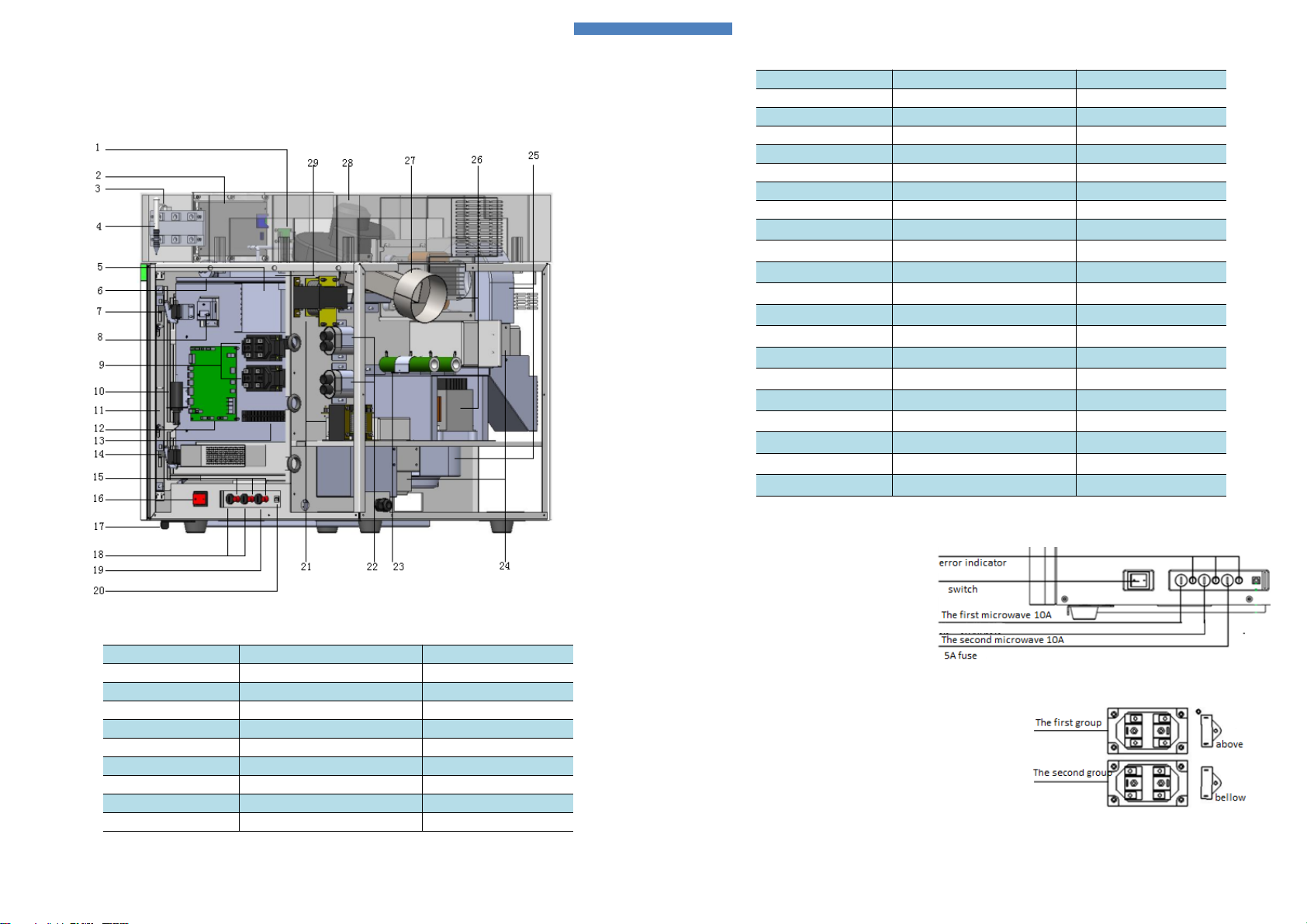
2-1 Axonometric views
Fig 2.1 axonometric view
No. Describe Inventory code
1LCDconnector
26ea002
2LCD 00fa715
3 Stop button 00ca809
4Touch pen 26tj202
5Power adapter(5/12V) 00fb310
6Pressure sensor 00fa602
7 Interlock switch 00ca801
8Pin hole camera 00fz005
9Thyristor 00ca211
8
TOPEX service manual
Note: We normally obey the rules that from left to right, front to back,upper to lower to define the first
microwave components and the second microwave components.
Forexample,wedefinetheleft fuse
holder and fuse belong to the first
microwave group, and the second
belongs to the second part,refer to fig 2.2
.
Fig 2.2 Fuse holders
We define the above thyristor belongs to fisrt group, and the
bellow one belongs to the second group.
Other components like magnetrons,high voltage items can be
define like this way.
Fig 2.3 Thyristor define
No. Describe Inventory code
10 Electromagnet 00fb808
11 Door bracket 26aa003
12 Main control board 26ea001
13 Terminal board 00ce802
14 Interlock switch 00ca801
15 Error indicator light 00ca904
16 Switch 00ca806
17 Latch handle 23aa015
18 Fuse holder\10A fuse 00ca704\00ca606
19 Fuse holder\5A fuse 00ca704\00ca615
20 PC connector board 26ea003
21 Filament transformer 00fa311
22 High voltage capacitor 09tj222
23 Resistor 00ca521
24 Magnetron 26tj207
25 Cooling fan 00fa111
26 High voltage transformer 09tj210
27 Exhaust pipe 22aa006
28 Exhaust fan 09tj206
29 Power adapter(24V)00fb308
9
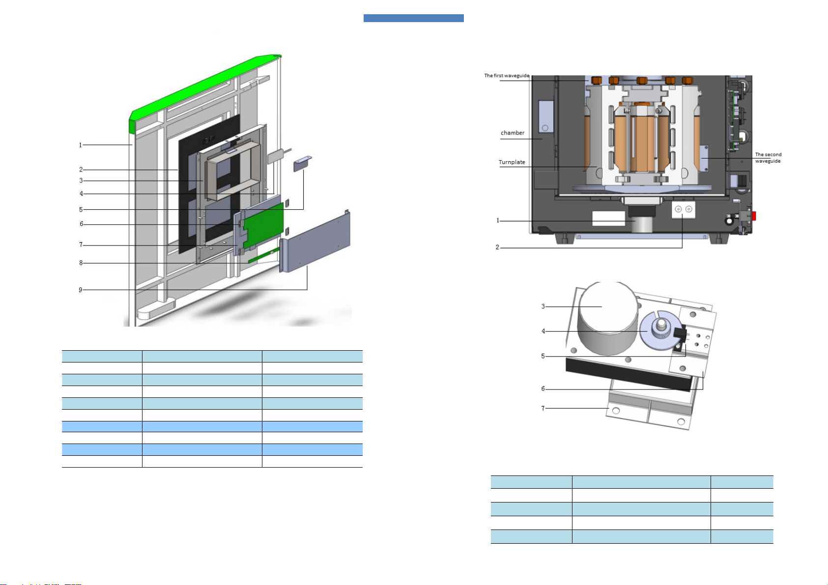
2-2 Safety door disassemble
Fig 2.2 safety door
No. Describe Inventory code
1Door shell 26da005
2Window board 26da011
3Bracket 26aa013
4LED light 00cz021
5Pressure plate 26aa015
6PCB board Built in monitor
7monitor 00fa704
8Power PCB Built in monitor
9Holder 26aa014
10
TOPEX service manual
2-3 Bottom view
Fig 2.3 bottom components
Fig 2.4 motor sub-assembly
No. Describe Inventory code
1 Motor components 26tj206
2Filter 00fb402
3 motor 00fa204
4grating 23ba004

11
2-4 Main control board layout
No. Describe Inventory code
5Photoelectric sensor 26tj205
6bracket 23aa020
7bracket 09aa042
12
TOPEX service manual

13
3 Commonly used spare parts replacement
This section introduce the process of spare parts replacement,please refer to these processes.
3-1 Magnetron replacement
Fig 3-1 Magnetron mounted position
Magnetrons are mounted at the back side of the chamber as fig 3‐1 described.We define the above magnetron
belongs to the first microwave group, the below one belongs to the second group.
Temperature relay is installed on the surface of the magnetron.
Note: Exhaust duct is mounted with magnetron, please don’t take dow
n
when replace the magnetron.
Fig 3-2 magnetron
The second magnetron
The first magnetron
温控器
风罩
Nuts
Exhaust duct Temperature
relay
14
TOPEX service manual
3-2 Magnetron cooling fan repalcement
Fig 3‐3 Magnetron cooling fan mounting position
Magnetron cooling fan is installed nearby the magnetron,mounted with bracket. Starting capacitance is
installed on the surface of the cooling fan.
Fig 3‐4 Cooling fan and bracket
Fig 3‐5 describes the wiring way for magnetron.
Fig 3‐5 wiring layout
The second cooling fan
The first cooling fan
Fixed holes
Nuts

15
3-3 HV transformers replacement
Fig 3‐6 HV transformer mounted position
Two magnetrons are covered by metal covers to form a duct reduce the temperature of transformers,refer to
fig3‐6.Therearetwopointsneedtonotewhenmaintenance engineer wants to take down the metal covers.
(1) It is no need for take down the fixed nuts, it is OK to unscrew,refer to fig 3‐7.
(2) two wiring resistors are installed on the surface of the metal cover,fixed nuts an
d
screws for mental cover need to be taken down, maintenance engineer should pa
y
more attention to the wiring layout and recover the wiring after replacement
Fig 3‐7Fixednuts
The first transformer is fixed like fig 3‐8, take down four fixed nuts and
disconnect the cord. We can do replacement process. Two HV
transformers are installed as the same way.
Wiring layout
We normally do not stipulate the input wiring way, that is to say live and
neutral cord can be connected with HV transformer randomly.
Make sure reliable grounding between HV transformer and chamber.
.
Fig 3‐8 HV transformer
The second HV transformer
The first HV transformer
Metal cover
16
TOPEX service manual
3-4 HV capacitor replacement
Fig 3‐9 HV capacitor mounted positon
Two HV capacitor are installed at the back side of the chamber, refer to fig 3‐9, both of them are fixed by a
metal bracket. It is relatively easy for replacement.
Wiring layout for HV components
Caution: Incorrect wiring may cause faults like fuse blown or no microwave generated.
Fig 3-10 Wiring layout
The first one
The second one

17
3-5 Thyristor replacement
Fig 3‐11 thyristor mounted position
Two thyristors are mounted at the right side of the chamber,refer to fig 3‐11,take down the right ABS
cover, you will see them.
Thyristor is fixed by four M4 screws, the left side is input terminal and the right side is output terminal.
Fig 3‐12 Thyristor
Thyristor wiring layout
Refer to fig 3‐12, one of the input terminals nearby signal teminal is neutral, and the other is live. Neutral side
is always conductive between input and output,but the live is controlled by thyristor,its conductive feature is
controlled by signal.Control signal is afford from JP4‐15~20 pins,pin 15,17 and 19 belong to the first
thyristor,pin 16,18 and 20 belong to the second one, the range of control signal is from 0 to 10 direct current
represent various power.
The first one The second one
18
TOPEX service manual
Fig 3‐13 is the wiring layout of thyristor.
Fig 3‐13 Thyristor wiring layout
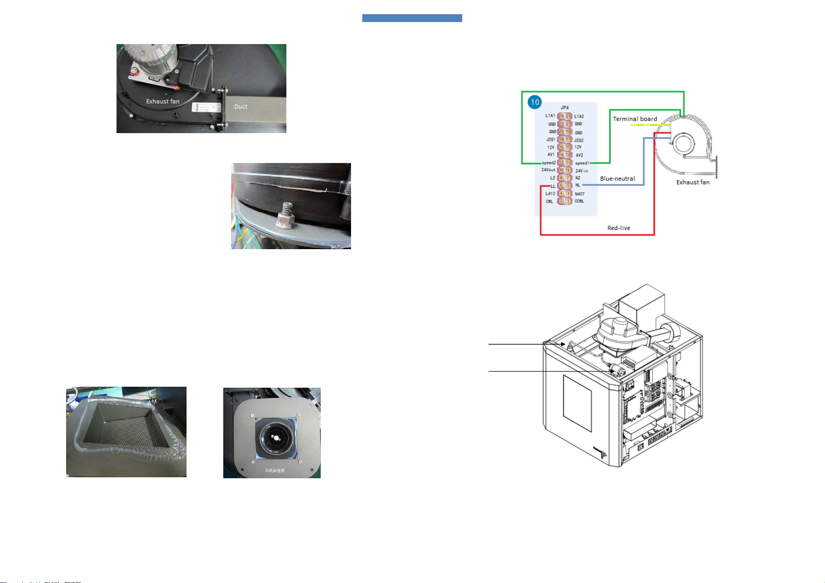
3-6 Exhaust fan replacement
Fig 3‐14 Exhaust fan mounted position
Exhaust fan is installed at the top of chamber ,refer to fig 3‐14. Take down plastic covers,then you can
replace the exhaust fan.Exhaust fan is assembled with exhaust duct together, so it is no need for disassembling
them when you want to replace exhaust fan,refer to fig 3‐15.
19
Fig 3‐15 Exhaust fan unit
Exhaust fan replacement sequence:
(1) Take down three M5 nuts, refer to fig 3‐16.
(2) Disassemble the exhaust fan and duct.
(3) Take down the connection bracket installed with exhaust
fan.
Fig 3‐16 M5 fixed nuts
Exhaust fan installation
(1) Clean up the sealing silicone,cover with a layer of silicone again,refer to fig 3‐17.
(2) Use four screws to fix the connection bracket onto the exhaust fan with a layer of sealing silicone,refer to
fig 3‐18.
(3) Use four screws and nuts to fix exhaust fan and duct, the gap should be filled with sealing silicone.
(4) Remount the exhaust fan fixed by three M5 nuts,refer to fig 3‐16.
(5) Restore wiring connection.
Fig 3‐17 Sealing silicone Fig 3‐18 Connection bracket
Exhaust fan wiring diagram
20
TOPEX service manual
Exhaust fan wiring is divided into power cord and speed regulating signal lines,these wires ard controlled by
main control board JP4,JP4‐6 controls live and JP4‐5 controls neutral,seeped regulating signal is controlled by
JP4‐11,12,refer to fig 3‐19.
Fig 3-19 Exhaust fan wiring layout
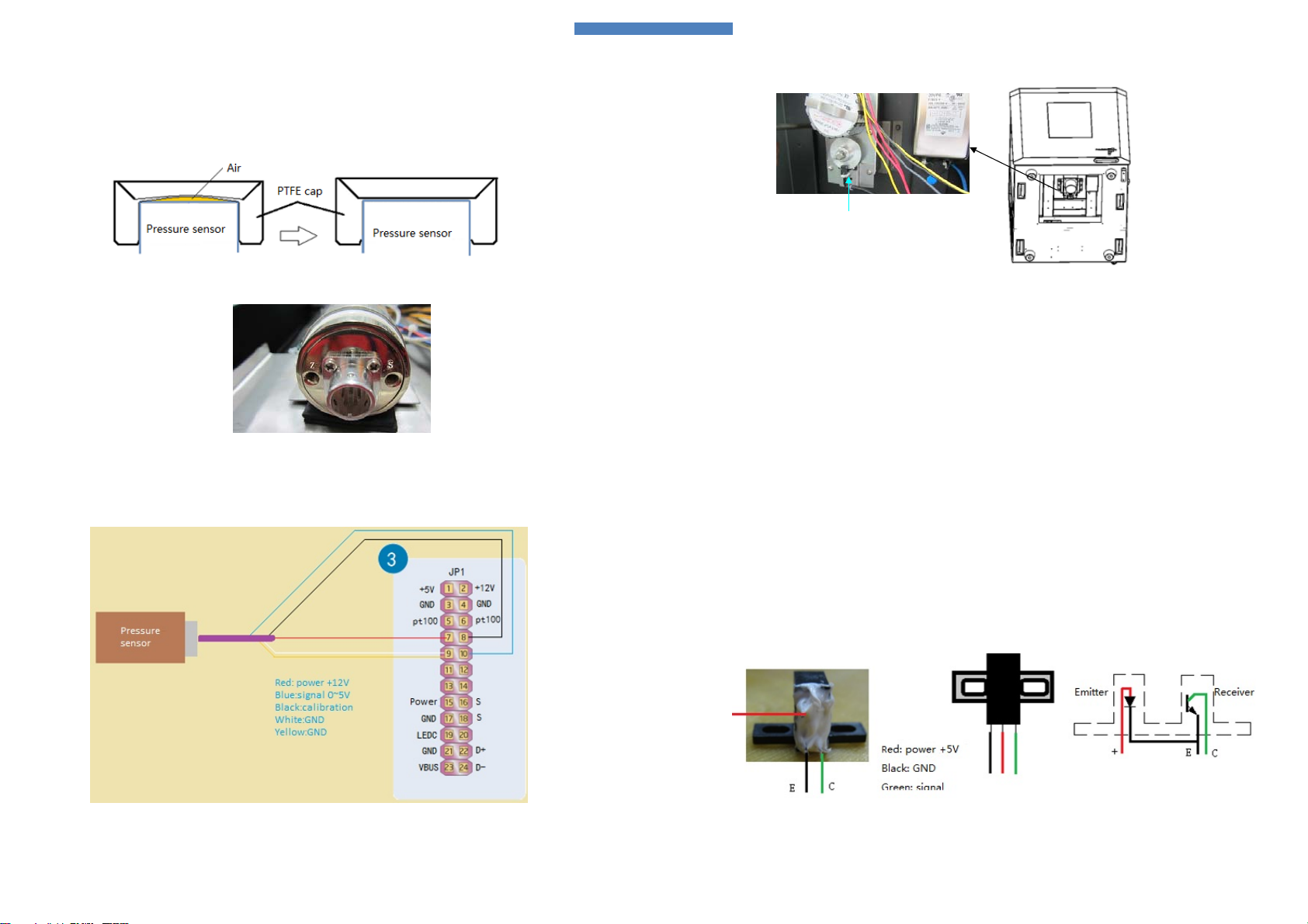
3-7 Pressure sensor replacement
Fig 3-20 Pressure sensor mounted position
Pressure sensor is mounted on the top of chamber, refer to fig 3‐20.One side is inductive terminal and the
other side is data cable.
Installation matters
Pressure sensor
Metal bracket
21
(1) Residual air between PTFE gap and pressure sensor should be drained entirely, or may cause insensitive
response and pressure lingering, refer to fig 3‐21.
(2) Screw thread of the pressure sensor should be covered with teflon seal tape about 3 layers.
(3) Side Z should be adjusted towards operator,refer to fig 3‐22.
Fig 3-21 Residual air
Fig3-22SideZ
Pressure sensor wiring layout
Pressure sensor data lines are connected with main control board JP1 pin7 to pin10,refer to fig3‐23.
Fig 3‐23 Pressure sensor wiring diagram
22
TOPEX service manual
3-8 Turntable motor replacement
Fig 3‐24 Turntable motor mounting position
Turntable motor is mounted at the bottom of the chamber by four M4 nuts.Turntable motor is a subassembly
gathered with metal bracket, photoelectric sensor and grating.
Note:
(1) Instrument should be overturned ,take down the black cover.
(2) Take the turntable and vessels out of chamber to avoid damage the sensors. It is no need to take down
thepressuresensorandgaspipe.
Photoelectric sensor replacement
Photoelectric sensor is installed on the surface of grating, used for turntable direction control.There are two
points need to know when operate the photoelectric sensor replacement.
(1) Cut the signal lines nearby the photoelectric sensor, peel off a short of insulating layer,then put insulating
heat shrink tube about D2 on signal lines separately.
(2) Weld the signal lines and photoelectric sensor together,refer to fig 3‐2, use heat shrink tube cover the
welding part finally to avoid short circuit.
Fig 3‐24 Photoelectric sensor feature
Photoelectric sensor

23
Wiring diagram for turntable motor subassembly
Turntable motor power cord is connected with main control board JP4 pin1 and pin 2, decide clock wise or anti
clock wise according to the signal from photoelectric sensor. Photoelectric sensor provides signal to main
control board through pin 15, pin 16 and pin 17, refer to fig 3‐25.
Fig 3‐25 Turntable motor subassembly wiring layout
3-9 LCD replacement
Touch screen is mounted in top ABS cover, refer to fig 3‐26.
Fig 3‐26 LCD subassembly
24
TOPEX service manual
LCD is fixed by four M3*6 screws, data communication type is serial communication via a LCD connector
connected with main control board, refer to wiring diagram.There are four points need to pay more attention
when maintenance engineer disconnect the FPC flat cable.
(1) Clean up the locking silica gel, refer to fig 3‐27.
(2) Open the FPC fixed cover upward.
(3) Takedown FPC flat cable.
(4) Restore the FPC flat cable installation, use silica gel to lock the fixed cover at the same time.
Note:BluesidetowardsfixedcoverandtheothersidefacetoPCB.
Fig 3‐27 FPC connector
Stop button wiring layout
Fig 3‐28 Stop button define
Stop button is mounted at the upper right of TOPEX,is used to stop the microwave in emergency, refer to fig 3‐
28.

25
Metal bracket
PCB board
Monitor screen
Signal board
3-10 Built-in camera and monitor replacement
Monitor screen is mounted inside door shell, and the pin hole camera is located on the right side of the
chamber, there are two points need to pay more attention when disassemble the subassembly.
(1) Take down black cover fixed by eight M3*10 screws, then you will see six screws to fix the door shell, refer
to fig 3‐29.
(2) Take down door shell, replace relevant components.
Fig 3‐29 Safety door subassembly
Monitor subassembly relationship is described like fig 3‐30.
Fig 3‐30 Monitor screen subassembly
Note: Monitor and its PCB connection style is push‐pull way strange form LCD, refer to fig 3‐31.
Fig 3‐31 Push‐pull style
26
TOPEX service manual
Monitor system wiring diagram
Monitor system power supply is control by stop button,yellow line is video signal, refer to fig 3‐22.
Fig 3‐32 Monitor system wiring diagram
3-11 LED backlight replacement
LED backlight replacement needs to pay attention to plus‐n‐minus,refer to fig 3‐33.
Fig 3‐33 LED backlight
3-12 Push style electromagnet replacement
Push electromagnet is use to open the door automatically, located right side of chamber, its work voltage is
24V controlled by main control board, refer to fig 3‐34.
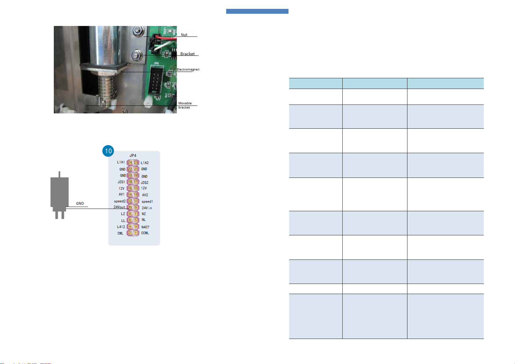
27
Fig 3‐34 Push style mounting location
Wiring diagram
Fig 3‐35 Electromagnet wiring layout
28
TOPEX service manual
4 Trouble shooting
For safety considering, maintenance engineer who can do some service work should be trained and approved
by PreeKem, and get the qualification.
Fault Probable cause Solution
No power
Fuse is blown
Socket is loosen
Replace related fuse
Insert socket again
No microwave
Fuse is blown
HV components error
Main control board error
Replace related fuse
Check HV components
Replace PCB
Microwave can not be
regulated
Thyristor fault
Main control board error
Mutual inductor broken
Replace related thyristor
Replace PCB
Replace mutual inductor
Discontinuous microwave Temperature error
Replace cooling fan (fan does not work)
Replace related temperature
Temperature value
unstable
Microwave interference
Temperature socket loosen
Temperature sensor
Main control board error
Check door gap
Re‐mount the temperature
Replace temperature
Replace PCB
Temperature reading value
error
No temperature signal
Main control board error
No calibration
Replace temperature sensor
Replace PCB
Calibrate temperature valve
Pressure value is not zero
when the actual pressure is
zero
No calibration
Main control board error
Pressure fault
Calibrate pressure error
Replace PCB
Replace pressure sensor
Pressure value unstable
Microwave disturb
Pressure sensor fault
Main control board error
Check door gap
Replace pressure sensor
Replace main control board
Spark in chamber Improper microwave power Set right microwave power
Crackle
Check HV transformers
Check HV diodes appearance
Check HV ca
Check filament transformer terminals
Check magnetrons appearance

29
Fault Probable cause Solution
Turntable does not work
Photoelectric sensor fault
Motor fault
Main control board error
Replace photoelectric sensor
Replace motor
Replace main control board
Touch screen fault
Resistance broken
No calibration
Main control board error
Replace touch screen
Calibrate touch function
Replace main control board
Garble code on screen
Bad data lines connection
LCD fault
Main control board error
Re‐installation the data lines
Replace LCD
Replace main control board
No video show
No video signal
No working voltage
Monitor screen fault
Replace pin hole camera
Check 12V power and its wiring
Replace monitor screen
No response for ‘auto open
door’ function
Exhaust fan is open
Main control board error
No 24V work voltage
Electromagnet fault
Axis of electromagnet decentration
Stop exhaust fan
Replace main control board
Replace power adapter (24V)
Replace electromagnet
Re‐mount the door mechanism
Warning :
“Time‐out”
No microwave
Wrong microwave power setting
Poor microwave absorb ability
Heating time is short
Check microwave generated components
Set right microwave power
Increase microwave power
Prolong heating time and set multi‐step
Warning:
“Temperature error”
Air leakage
Pressure sensor fault
Main control board error
Power is setted too large
Check the air impermeability
Replace pressure sensor
Replace main control board
Set related microwave power
Warning:
‘Pressure limited’
Power is setted too large
Pressure setting value is lower
Samples have good microwave
absorbing ability
Pressure sensor fault
Reduce microwave power
Increase setting value
Reduce microwave power
Replace pressure sensor
Warning:
‘Pressure control’
Lower pressure setting value
Main control board error
Increase setting value
Replace main control board
Warning:
‘Turntable fault’
Photoelectric sensor fault
Main control board error
Turntable motor fault
Replace Photoelectric sensor
Replace main control board
Replace motor
30
TOPEX service manual
4-1 HV components measuring method
Measuring the HV components input or output terminals with the power on is forbidden.These HV
components can be estimated by measuring its resistance.Test behavior can only be operated 5 minutes
latter after power off.
4-1-1 Filament transformer
Disconnect the primary and secondary wiring terminals,the resistance of primary is about 20 Ωand the
secondary is 1 Ωnormally. If resistance is right, we can eliminate the doubt of filament transformer fault
4-1-2 HV transformer
Disconnect the primary and secondary wiring terminals,the resistance of primary is about 1.5Ωand the
secondary is nearly 100Ωnormally (between secondary and grounding).
Fault type: open circuit
4-1-3 HV capacitor
The resistance between two terminals is about 10MΩ.
Lower or higher resistance indicate the capacitor has been break down.
Resistance should escalate while the measuring process, if the resistance is directly fixed at 10MΩ,no
escalation process, that indicates the HV capacitor has been break down.
Fault type: Break down
4-1-4 HV diode
Take down HV diode
If no microwave generated and the surface temperature is too high that indicates HV diode has been
break down.
The resistance between anode and cathode is about 30 to 70MΩ.
The resistance between cathode and anode is infinite.
If the forward direction resistance is too high or reverse is too low beyond the standard indicates break
down.
The anode must be connected with HV capacitor and reliable grounding for cathode.
4-1-5 Magnetron
Resistance of filament cathode is nearly 1Ω.
Resistance between filament cathode and grounding is infinite.
Magnet flaws on magnetron is not allowed.

31
Fig 4-1 Magnetron appearance
Fault type: filament cathode open circuit, antenna spark, magnet flaws.
Caused faults: no microwave, lower microwave efficience, blown fuse and HV diode.
4-2 Infrared sensor
Type: OPTCSMLT15
Temperature range: 0~350℃
Output: 0~3.5V
Ratio: 15:1
Scale: 1℃\10mV
Wiring define:
4-3 Pressure sensor
Range: 0~5Mpa
Output: 0~5V
Scale: 1atm / 50mV
Filament cathode
32
TOPEX service manual
5. Fault cause analysis
5-1 No microwave generated
Maintenance engineer should confirm the fuses are not blown. If the fuse blown continually when start
microwave, the problem must be caused by short circuit hidden in HV components, such as thyristor, HV
capacitor,HV transformers and so on. Measuring method refer to chapter 4.
If HV components have good quality, the possible reasons are terminals spark.
Confirm related thyristor has input or output voltage. If no input voltage, the problem may caused by the
former components described on wiring diagram, and if no output voltage, the problem maybe caused by
thyristor error.
If the problem is still encounter, change the magnetron and have a try.
5-2 Garble microwave power match
Thyristor can not control its output voltage may cause this fault, there are three cause reasons.
(1) Power control signal afford by main control board is error.
(2) Thyristor is broken.
(3) Mutual inductor is broken.
5-3 Infrared display value error
Infrared temperature is compensated, so the real temperature is lower than reading value displayed on
screen, but they are both have a certain proportion relation.
Measuring the output signal, if the signal is too large or stable, this problem must be caused by fault main
control board.
If the signal does not up while the temperature go up, the IR sensor may be broken.
5-4 Pressure display value error
Observe the pressure value displayed on screen whether change or not to affirm fault through press the
sensitive terminal by thumb.
Measuring the output signal between blue and white, if the signal can match the displayed value, the
problem maybe caused by pressure sensor.
If there is no output signal or weak signal change, that’s probably the pressure sensor error.
Replace the pressure sensor after the fault confirmed to avoid difficult installation.
5-5 Other components faults
Other components work mechanism are relatively simple,right work voltage and good quality, these
problems can be easily deal with according to the wiring diagram.

33
6 Parameter calibration
6-1 Temperature calibration (PT100)
Disconnect the temperature sensor in chamber, use standard resistance box to calibrate the temperature
parameter, refer to fig 6‐1.
Fig 6-1 Wring layout for temperature calibration
(1) Use super password entering calibration interface, refer to fig 6‐4. There are one thing need to notice, that
is gray status represents lowercase and highlight represents uppercase, refer to fig 6‐2and6‐3.
Fig 6-2 Lowercase status
Status button
34
TOPEX service manual
Fig 6-3 Uppercase status
Fig 6-4 Temperature and pressure calibration interface
(1) Set 100.00Ω,clickbuttonRT0,refertofig6‐4, it’s no need to click OK button.
(2) Set 199.50Ω, click button RT1, finally click OK button to save.
(3) Disconnect resistance box, reinstall the temperature sensor, if the temperature value displayed on screen is
not right, the temperature should be calibrated again.
35
6-2 Pressure parameter calibration
Pressure parameter calibration should calibrate zero first then span, this sequence can not be reversed.
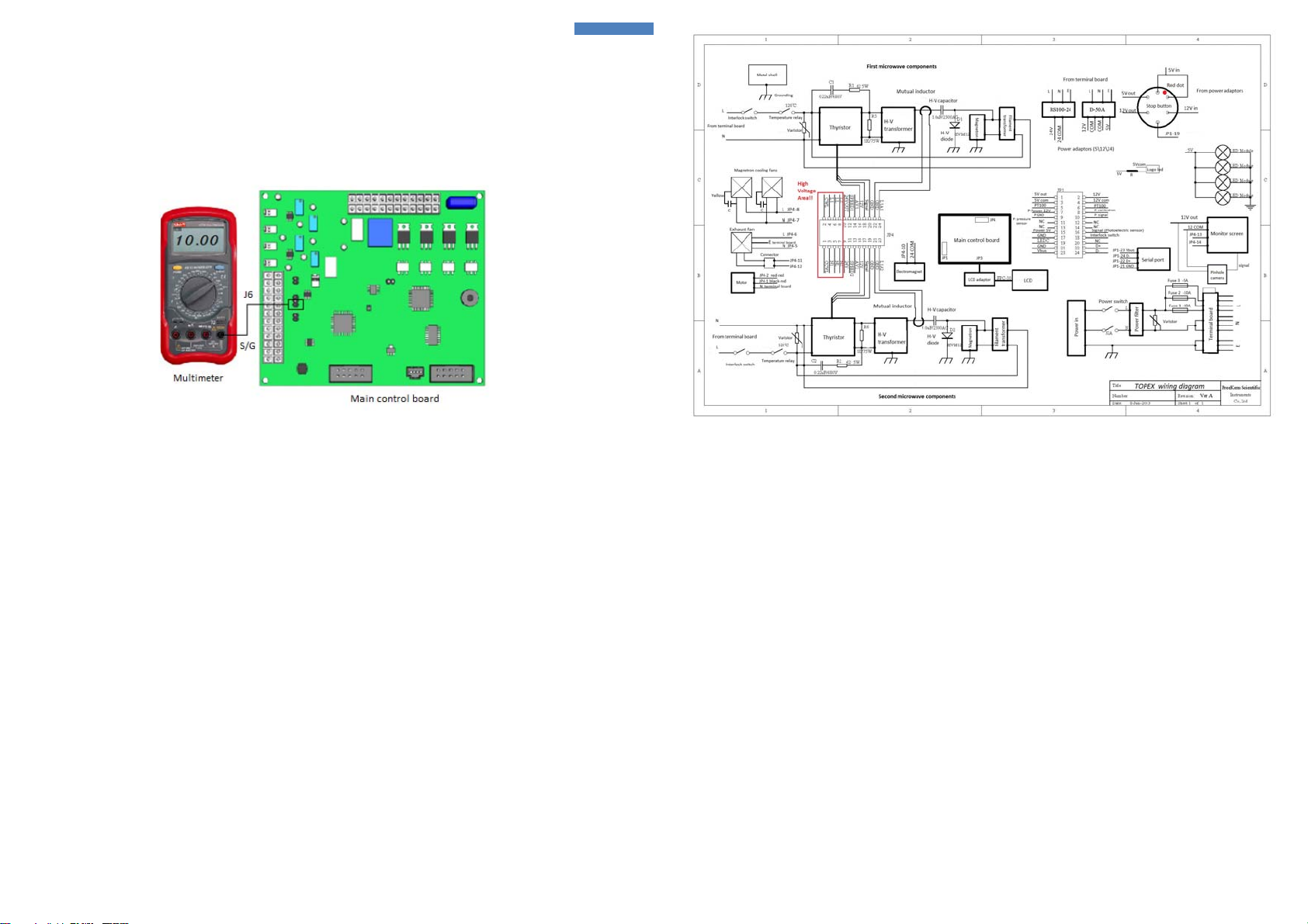
(1) Multimeter connects with J6 pin S and G on main control board, refer to fig 6‐5, adjust side Z until the
output voltage is 10 mV . This operation process is zero calibration
Fig 6-5 Wiring layout for pressure calibration
(2) Connect J6 pin G and J with a mini jumper, adjust side S until the output voltage is 4.00 V then entering
setting interface and press button RP, refer to fig 6‐4, finally click button OK to save calibration value. If the
value displayed on screen is not right, pressure parameter should be calibrated again.
7 Wiring diagram

Preekem Scientific Instruments Co.,Ltd.
No.2 Building,No.4299 Jindu Road,Shanghai,201108,China
Tel:86‐021‐5442‐7057
Fax:86‐021‐5442‐7063
E‐mail:[email protected]
Service manual
Ver 1.0
Table of contents
Other PreeKem Laboratory Equipment manuals

Popular Laboratory Equipment manuals by other brands


Omega Engineering
Omega Engineering WTM-1000 user guide

Thermo Scientific
Thermo Scientific Finnpipette FOCUS Instructions for use

Cleverscope
Cleverscope CS1090 Usage Guide

MRC
MRC LOM-150DIG Operation manual

Endress+Hauser
Endress+Hauser OXY5500 QF Safety instruction

Andrew Alliance
Andrew Alliance Waters Andrew+ user manual


