New York Air Brake IP-225-C User manual

© Copyright New York Air Brake. All rights reserved. CONFIDENTIAL
748 Starbuck Avenue, Watertown, NY 13601
Phone +1 315 786-5200 Engineering Fax: +1 315 786-5673
LIQUID CRYSTAL DISPLAY MONITOR
(LCDM)
OPERATOR MANUAL
IP-225-C
July 2011

IP-225-C 2 of 38 Rev. 01
© Copyright New York Air Brake. All rights reserved. CONFIDENTIAL
THIS PAGE INCLUDED FOR DOUBLE SIDED COPYING

IP-225-C 3 of 38 Rev. 01
© Copyright New York Air Brake. All rights reserved. CONFIDENTIAL
Revision
Level Section Change Date
01 ALL Original Release July/11

IP-225-C 4 of 38 Rev. 01
© Copyright New York Air Brake. All rights reserved. CONFIDENTIAL
THIS PAGE INCLUDED FOR DOUBLE SIDED COPYING

IP-225-C 5 of 38 Rev. 01
© Copyright New York Air Brake. All rights reserved. CONFIDENTIAL
TABLE OF CONTENTS
Table of Tables .............................................................................................................................................7
1.0 INTRODUCTION..............................................................................................................................8
2.0 general.............................................................................................................................................8
2.1 Definition of Temperatures ..........................................................................................................8
2.2 Abbreviations...............................................................................................................................8
2.3 Standards list with status of issues..............................................................................................8
3.0 PRODUCT DESCRIPTION..............................................................................................................9
3.1 Introduction..................................................................................................................................9
3.2 Features.......................................................................................................................................9
3.3 Electronic Components .............................................................................................................10
4.0 Mechanical drawings......................................................................................................................13
4.1 Version 782340/782343 with keyboard.....................................................................................13
4.2 Version Tbd with Touch Panel...................................................................................................14
5.0 Technical Data...............................................................................................................................16
5.1 Climate and environmental conditions.......................................................................................16
5.2 Mechanical Data........................................................................................................................16
5.3 Electrical data............................................................................................................................17
6.0 Further utiliZation notes .................................................................................................................19
6.1 Important Notice ........................................................................................................................19
6.2 Transportation............................................................................................................................19
6.3 Storage......................................................................................................................................19
6.4 Handling front membranes........................................................................................................19
6.5 Environmental details on materials............................................................................................19
7.0 Installation requirements................................................................................................................20
7.1 Installation conditions ................................................................................................................20
8.0 Installation......................................................................................................................................21
8.1 Installation Regulations/Notes...................................................................................................21
8.2 Plug-pin assignments ................................................................................................................22
9.0 Commissioning and system parameters........................................................................................29
9.1 Important Notice ........................................................................................................................29
10.0 Operation .......................................................................................................................................30
10.1 Operating instructions................................................................................................................30
10.2 Operation and display................................................................................................................30
11.0 Diagnostics and service functions..................................................................................................34
11.1 Connection of a MF2-compatible USB keyboard and USB mouse...........................................34
11.2 Using the Ethernet interface for the service..............................................................................34
12.0 Maintenance...................................................................................................................................35
12.1 Important Notice ........................................................................................................................35
12.2 Smallest exchangeable unit.......................................................................................................35
12.3 Preventive maintenance............................................................................................................35
12.4 Corrective maintenance.............................................................................................................36
13.0 Decommissioning...........................................................................................................................37
13.1 Important Notice ........................................................................................................................37
13.2 Disassembly ..............................................................................................................................37
13.3 Abbreviations.............................................................................................................................38

IP-225-C 6 of 38 Rev. 01
© Copyright New York Air Brake. All rights reserved. CONFIDENTIAL
TABLE OF FIGURES
Figure 2-1 Temperature Ranges According to EN 50155 ...........................................................................8
Figure 3-1 LCDM Multi-Functional Terminal................................................................................................9
Figure 4-1 Front View with Dimensional Drawing (782340/782343) .........................................................13
Figure 4-2 Rear View with Dimensional Drawing 782340/782343 ............................................................13
Figure 4-3 Side View 782340/782343 (upright).........................................................................................14
Figure 4-4 Front View with Dimensional Drawing (Tbd)............................................................................14
Figure 4-5 Rear View with Dimensional Drawing Tbd (example illustration of labels) ..............................15
Figure 4-6 Side View Tbd (upright)............................................................................................................15
Figure 8-1 Connectors (rear view).............................................................................................................22
Figure 10-1 LEDs and Sensors of the LCDM ............................................................................................30
Figure 10-2 Operation of LCDM with Keyboard (782340/782343)............................................................32
Figure 12-1 “Battery Replacement” Sticker on the Back of the Device (example)....................................36

IP-225-C 7 of 38 Rev. 01
© Copyright New York Air Brake. All rights reserved. CONFIDENTIAL
TABLE OF TABLES
Table 3-1 – Status LEDs.............................................................................................................................11
Table 3-2 Overview of Acoustic Signaling Transmitter............................................................................11
Table 8-1 Plug-Pin Assignment X1............................................................................................................23
Table 8-2 Plug-Pin Assignment X2............................................................................................................24
Table 8-3 Plug-Pin Assignment X3............................................................................................................25
Table 8-4 Plug-Pin Assignment X10a........................................................................................................26
Table 8-5 Plug-Pin Assignment X10b........................................................................................................26
Table 8-6 Plug-Pin Assignment X18..........................................................................................................27
Table 8-7 Plug-Pin Assignment X20..........................................................................................................28
Table 10-1 LEDs and Sensors...................................................................................................................31
Table 10-2 Possible Keyboard Assignment (782340/782343) ..................................................................33

IP-225-C 8 of 38 Rev. 01
© Copyright New York Air Brake. All rights reserved. CONFIDENTIAL
1.0 INTRODUCTION
The purpose of this operator’s manual is to assure that the product is used appropriately and
safely.
2.0 GENERAL
2.1 Definition of Temperatures
Operating temperature:
Air temperature (in max. and min. limits) in the immediate environment of the device,
at which the device is permitted to be operated.
Storage temperature:
Air temperature (in max. and min. limits) around the device at which the device is
permitted to be stored (equipment is isolated from power supply).
Ambient temperature (in accordance with EN 50155)
1. Outside ambient temperature
2. Temperature inside the cabinet (Device ambient temperature)
3. Temperature of the air surrounding the printed circuit board module (temperature
inside the device).
Figure 2-1 Temperature Ranges According to EN 50155
(using a driver’s console as an example)
2.2 Abbreviations
Refer to Appendix A for a complete list of abbreviations used in this document.
2.3 Standards list with status of issues
In this document the standards will only be designated by their standards number.
Appendix B contains the standards with their complete designations and respective
status of issue. More standards can be listed in this table than are necessary for the
product.

IP-225-C 9 of 38 Rev. 01
© Copyright New York Air Brake. All rights reserved. CONFIDENTIAL
3.0 PRODUCT DESCRIPTION
3.1 Introduction
The LCDM multi-functional terminal is used in complex control and guidance systems
as a man-machine interface. It displays process data and receives inputs from the
operator.
Data entry occurs via keyboard (version 782340 or 782343) or via a touch panel
(version Tbd).
Operation of keyboard version is designed with 11 function keys (softkeys).
The LCDM is based on a single-board PC (“embedded PC”) with a GEODE processor.
An active matrix color display (TFT) is used for the display.
Figure 3-1 LCDM Multi-Functional Terminal
3.2 Features
Power supply with galvanically isolated voltage converter (74 VDC or 110 VDC)
Active Matrix color display (TFT) with background lighting, 640 x 480 pixel, 10.4"
Resistive touch panel (Tbd only)
4x COM interfaces (RS422 (HDLC supported)

IP-225-C 10 of 38 Rev. 01
© Copyright New York Air Brake. All rights reserved. CONFIDENTIAL
1x COM interface RS232 (for service)
1x Ethernet interface (10/100 BaseT, with M12 connector, d-coded)
2x USB 1.1 interfaces (M8 connector)
11 illuminated function keys (softkeys)
Operating temperature 782340/782343: -31 F...+158 F (-35 C...+70 C)
Operating temperature Tbd: -13 F...+158 F (-25 C...+70 C)
No moving parts such as fan, hard disks, etc.
Protection against formation of condensation in the device
3.3 Electronic Components
3.3.1 Power Supply
The power unit can be adapted to the desired battery voltage with the aid of
different DC/DC converters.
The 782340 and Tbd are equipped with a DC/DC converter for 74V battery
voltage, and the 782342 has a DC/DC converter for 110V.
The device is protected against reverse polarity electrically by the
corresponding safety elements as well as mechanically by a plug notch.
The device does not have any externally accessible fuses. The device must be
replaced if faulty (see Chapter 13.4 "Corrective maintenance" on page 58).
The power consumption of the LCDM is typically 20 W (without heating),
maximally 30 W.
3.3.2 TFT display
The device has a 10.4" TFT display.
The display can portray 640 x 480 pixel with a color depth of 18 bit (262,144
colors) and a read angle of ±60° horizontal and -55° ...+45°vertical to surface
normal.
3.3.3 Background lighting (display)
Two CCFL tubes are used for the background lighting of the display. The
brightness of the CCFL tubes is controlled by an environment controller. The
controller can switch the background lighting on and off as well as adapt the
brightness automatically to the ambient brightness and simultaneously
superpose a manually set brightness value. The tubes can be easily replaced.
The keyboard is illuminated by LEDs.

IP-225-C 11 of 38 Rev. 01
© Copyright New York Air Brake. All rights reserved. CONFIDENTIAL
3.3.4 Optical sensor
An optical sensor in the front measures the ambient brightness and can adjust
the display background lighting as necessary.
3.3.5 Heating
For heating the device at low ambient temperatures, heaters are located
directly on the main board. When the PC-part is switched on, only one heater
can be activated. The heater is activated automatically by an environment
controller.
3.3.6 Status LEDs
Three (3) Status LEDs, whose functions are partially pre-installed, are located
in the front. The LEDs can be activated from the application via envcon
daemon. The LED colors are:
Designation Color Function
LED 1 Red Error status (optional)
Freely Available via AP1
LED 2 Yellow Operating state display:
Off – Device is off
On – Device is ready for operation
1 Hz Blinking – Device is outside of
operating temperature
4 Hz Blinking – Device off, watchdog
limit achieved
LED 3 Blue Freely available via AP1
Table 3-1 – Status LEDs
3.3.7 Acoustic Signaling Transmitter
782340/782342 tbd
Location Main board Rear panel
Form Miniature piezoelectric buzzer Miniature piezoelectric buzzer
Volume 85 dB (at 24” (60 cm) distance,
free field) 85 dB (at 24” (60 cm) distance, free
field)
Frequency 4 kHz 2.75 kHz
Table 3-2 Overview of Acoustic Signaling Transmitter
Activation can occur through the application via envcon daernon.

IP-225-C 12 of 38 Rev. 01
© Copyright New York Air Brake. All rights reserved. CONFIDENTIAL
3.3.8 System clock
When powering up the operating system, the system time is synchronized with
the time value of the high-precision RTC of the main board.
3.3.9 Keyboard
The LCDM is delivered with 11 soft-keys. The keys are illuminated.
3.3.10 Ethernet
An Ethernet interface according to 10/100BaseT with M12 connector, d-coded,
is implemented.
3.3.11 Four (4) serial interfaces RS422/RS485
The serial interfaces are electrically isolated RS422 and capable of sending
and receiving data via HDLC protocol. Please observe Chapter 8.2 "Plug-pin
assignment" as of Page 22 for a more detailed explanation of these interfaces.
3.3.12 Serial interface RS232 (Maintenance)
The RS232 interface is provided for connecting a Service PC. Please observe
Chapter 8.2 "Plug-pin assignment" as of Page 22 for a more detailed explanation
of this interface.
3.3.13 USB
There are 2 USB ports for external devices: two interfaces are available via two
M8 connectors which fulfill the V1.1 standard and which work with up to 12
MBit/s. For operating systems without USB support, the Legacy Mode for USB
keyboards is supported by the BIOS.
IP-225-C 13 of 38 Rev. 01
© Copyright New York Air Brake. All rights reserved. CONFIDENTIAL
4.0 MECHANICAL DRAWINGS
4.1 Version 782340/782343 with keyboard
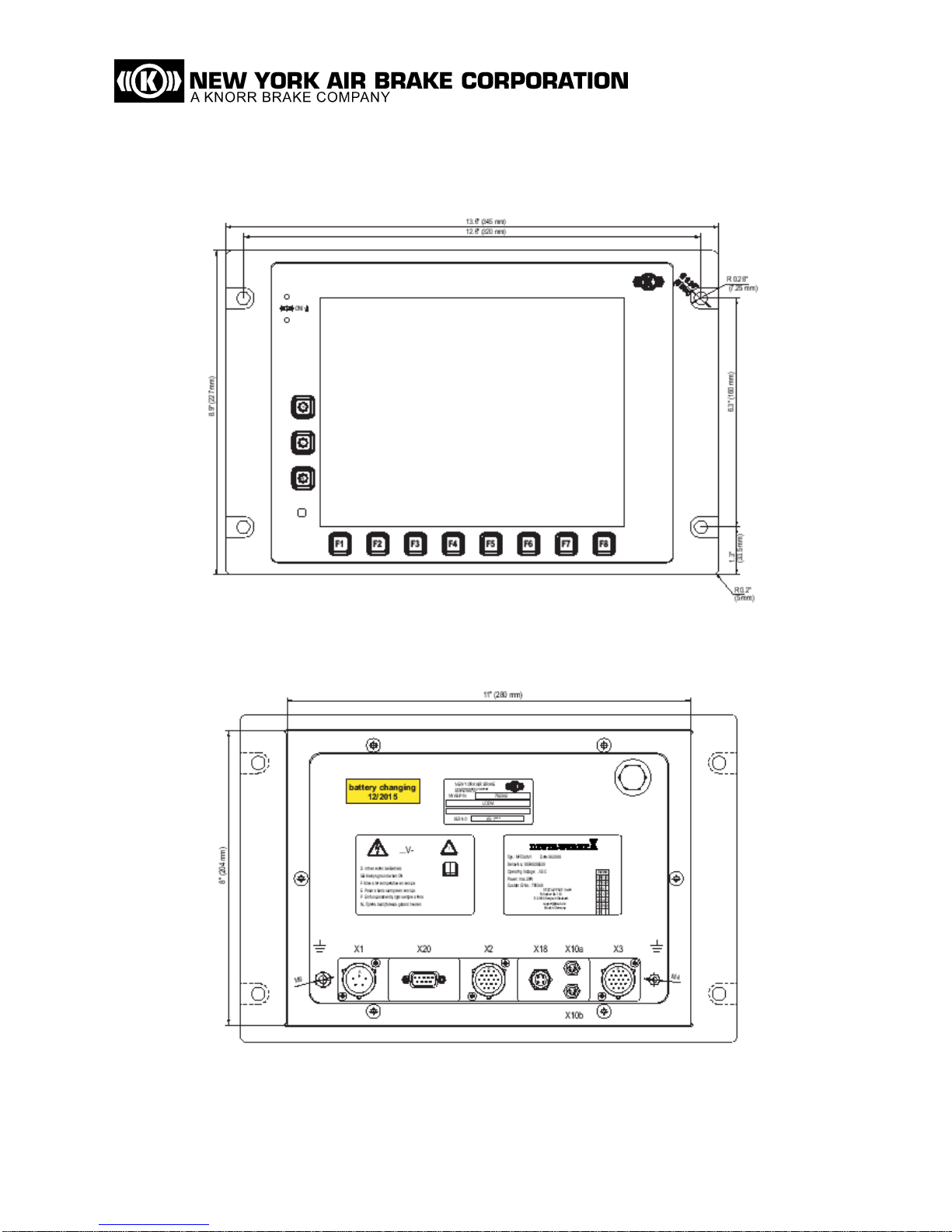
Figure 4-1 Front View with Dimensional Drawing (782340/782343)
Figure 4-2 Rear View with Dimensional Drawing 782340/782343
(example illustration of labels)

IP-225-C 14 of 38 Rev. 01
© Copyright New York Air Brake. All rights reserved. CONFIDENTIAL
Figure 4-3 Side View 782340/782343 (upright)
4.2 Version Tbd with Touch Panel
Figure 4-4 Front View with Dimensional Drawing (Tbd)

IP-225-C 15 of 38 Rev. 01
© Copyright New York Air Brake. All rights reserved. CONFIDENTIAL
Figure 4-5 Rear View with Dimensional Drawing Tbd (example illustration of labels)
Figure 4-6 Side View Tbd (upright)

IP-225-C 16 of 38 Rev. 01
© Copyright New York Air Brake. All rights reserved. CONFIDENTIAL
5.0 TECHNICAL DATA
5.1 Climate and environmental conditions
5.1.1 Operation temperature
782340/782343 -31
F...+158 F (-35 °C...+70 °C)
Tbd -13
F...+158 F (-25 ~C...+70 C)
5.1.2 Storage
Temperature -31 F...+185 F (-35 °C...+85 °C)
5.1.3 Humidity
Humidity in accordance with EN 50155
5.1.4 Shock/vibration
Shock/vibration in accordance with EN 50155
5.1.5 Fire protection
Fire protection in accordance with DIN 5510 Part 2
5.2 Mechanical Data
5.2.1 Dimensions
Width 11” (280 mm), with front frame 13.6” (345 mm)
Height 8” (204 mm), with front frame 12.6” (227 mm)
Depth 1.7” (47 mm), with front frame 2” (53 mm)
5.2.2 Weight
Weight Approximately 7.49 lbs (3.4 kg, depending on
equipment of model)
5.2.3 Protection Category
Housing IP54 (with attached wiring and unused plugs covered with a cap)
Front IP65 (when installed)
5.2.4 Other
Front Membrane polyester

IP-225-C 17 of 38 Rev. 01
© Copyright New York Air Brake. All rights reserved. CONFIDENTIAL
Display Cover scratch-resistant toughened glass panel,
0.16" (4 mm) thick
The glass panel is inserted flush with the front membrane.
It is an anti-glare design with a glare value of 100.
Touch Panel (Tbd only) polyester, antireflection
Chemical compatibility in accordance with DIN 42115.
5.3 Electrical data
5.3.1 Power supply
5.3.1.1 782340/782342
Connection reverse polarity protected
Nominal voltage 74VDC (25VDC...135VDC)
Power consumption typ. 20 W (without heating)
max. 30 W
max. starting current 25 A (30 µs.. .-50 µs)
Dielectric strength
Supply voltage primary against secondary / housing:
1,500VAC
Galvanically isolated circuits against housing:
2,000VAC (RS422),
1,000VAC (Ethernet, RS232)
Non galvanically isolated circuits against housing:
due to internal connection between secondary 0V and housing, this
dielectric strength is not given
5.3.1.2 tbd
Connection reverse polarity protected
Nominal voltage 110VDC (66VDC...154VDC)
Power consumption typ. 20 W (without heating)
max. 30 W
max. starting current 25 A (30 µs.. .-50 µs)
Dielectric strength
Supply voltage primary against secondary / housing:
1,500V AC
Galvanically isolated circuits against housing:
2,000V AC (RS422),
1,000V AC (Ethernet, RS232)
Non galvanically isolated circuits against housing:
due to internal connection between secondary 0V and housing, this
dielectric strength is not given.

IP-225-C 18 of 38 Rev. 01
© Copyright New York Air Brake. All rights reserved. CONFIDENTIAL
5.3.1.3 Interfaces
Ethernet according to IEEE 802.3 10 Base T
and 100 Base Tx with M12 d-coded
4x serial interfaces according to IEEE RS422
resp. IEEE RS485, HDLC protocol
2x USB according to USB1.1, up to 12 MBit/s
according to IEEE RS232
5.3.2 TFT Display
Size 10.4” (visible diagonal measure)
Display Range 8.3” x 6.2” (211.2.mm x 158.4 mm)
Resolution 640 x 480 pixel (VGA)
Number of Colors 262,144 (18 bit)
Pixel Pitch 0.01” x 0.01” (0.33 mm x 0.33 mm)
Viewing Angle Vertical -55° to +45°
Horizontal -60° to +60°
Luminance max 550 nt (550 cd/m2)
(utilixsable 0 nt…
480nt (0 cd/m2…480cd/m2))
Contrast typical: 300:1
Response time typical: tr15 ms
tf35 ms
Design in accordance with ISO 13406-2
5.3.3 Acoustic Signaling Transmitter
782340/782343
Signal Level approx. 85 dB at 24” (60 cm) free field distance
approx. 4 kHz continuous
Tbd
Signal Level approx. 85 dB at 24” (60 cm) free field distance
approx. 2.75 kHz continuous

IP-225-C 19 of 38 Rev. 01
© Copyright New York Air Brake. All rights reserved. CONFIDENTIAL
6.0 FURTHER UTILIZATION NOTES
6.1 Important Notice
Check for complete delivery
Carefully unpack the LCDM. Check for completeness, correct type, and correct
connections as well as for possible signs of transport damage. Dispose of the
packaging only after completing these steps.
6.2 Transportation
Transportation of the LCDM should only occur in the originally supplied or similar
packaging.
When returning the LCDM, sufficient protective measures must be made to avoid
damaging the device.
6.3 Storage
Storage temperature -31 °F...+185 °F (-35 °C...+85 °C)
Storing the LCDM should only occur in the originally supplied or similar packaging.
6.4 Handling front membranes
For devices with a front membrane, the following points must be observed in particular:
It may not be operated or actuated with pointed or sharp-edged objects.
It may not be operated or actuated permanently, such as can happen if the device is
stored face downwards or if keys are wedged.
It may not be cleaned with strong detergents or brought into contact with solvent or
caustic chemicals. A list of compatible chemicals can be obtained from NYAB.
6.5 Environmental details on materials
All materials are halogen-free, asbestos-free and are rustproof. Environmentally
hazardous or harmful materials as well as PCB-bearing capacitors and materials are
not used.

IP-225-C 20 of 38 Rev. 01
© Copyright New York Air Brake. All rights reserved. CONFIDENTIAL
7.0 INSTALLATION REQUIREMENTS
7.1 Installation conditions
This section is aimed solely at trained electricians. Basic knowledge of installation,
EMC measures and safe behavior is required.
NOTE
In order to avoid malfunctions or damage, all the instructions
in this section must be complied with.
Designated operational location
The equipment is intended for use on rail vehicles. It is installed in the driver’s cab.
Installation conditions
A permanently secured connection to the vehicle earth (operating earth) must be
established at the prescribed connection (earthing bolts). This requires a maximum 3 ft
(1 m) long metal braid with a minimum diameter of 0.015 sq in (4 mm
2
). The service
and maintenance personnel must be electro-statically discharged to protect the
operating resource.
Wiring and signal requirements
The supply voltage (battery voltage) and all related signals may not be connected to
the operating earth; otherwise the potential isolation in the device will be cancelled and
safe operation cannot be guaranteed.
Signal reference to the vehicle battery is only permitted for the supply voltage. Lines
with battery-related signals may not be fed to the unit in combination with the signaling
lines.
Shielded cabling throughout is specified for the lines of the RS-422 serial interfaces.
The shield must be applied to the side of the LCDM device by a conductive plug
housing. Preferably, the shield should be applied on both sides.
The service interfaces Ethernet, RS-232 and the USB interfaces are only for testing
and diagnosis purposes and may not be connected when the vehicle is in operation.
The braided screens of all screened cables must have an optical range of at least 85%.
The connections to the line screens shall be made appropriately in relation to EMC. All
shielding and earth connections must be connected via a broad contact surface.
Unused plugs must be covered with a cap.
Evaluation and peripheral device requirements
All connected devices must comply with the technical specifications given in the
operating instructions to ensure correct function.
Table of contents
Other New York Air Brake Monitor manuals


