New York Air Brake IP-235 User manual

....................
....................
....................
....................
Rail Vehicle Systems
IP-235
Rev. 03 (1/7/15) -en
782342assy1
Instruction Manual
Locomotive Cab Display Module (LCDM)

Locomotive Cab Display Module (LCDM)
Maintenance Manual Doc. No. IP-235
Revision: 03 1/7/15-en
This document was originally written in English.
Knorr-Bremse Group Page 2 / 40
Copyright 2015© NYAB. All rights reserved, including industrial property rights applications.
NYAB retains any power of disposal, such as copying and transferring.
Contact address
New York Air Brake Ltd.
748 Starbuck Avenue
Watertown, NY 13601
USA
Phone: +1 315 786 5200
Fax: +1 315 786 5676
www.nyab.com
Knorr-Bremse Group Page 3 / 40
Copyright 2015© NYAB. All rights reserved, including industrial property rights applications.
NYAB retains any power of disposal, such as copying and transferring.
Locomotive Cab Display Module (LCDM)
Maintenance Manual Doc. No. IP-235
03
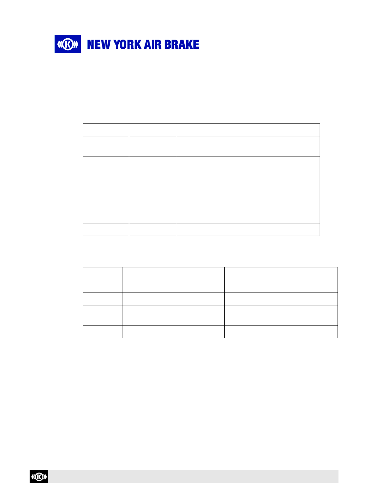
Revision History
Rev. Date Name Para Description of Change
01 4/22/10 T. Lumbis ALL Original Release
02 1/21/13 J. Marra ALL Reformat and restructure
03 1/7/15 K. Deon 5.1.3 Added procedure to manually set time
and date

Knorr-Bremse Group Page 4 / 40
Copyright 2015© NYAB. All rights reserved, including industrial property rights applications.
NYAB retains any power of disposal, such as copying and transferring.
Locomotive Cab Display Module (LCDM)
Maintenance Manual Doc. No. IP-235
03
Table of contents
1 General Information 7
1.1 Introduction 7
1.2 Technical changes 7
1.3 Target Group for this Document 7
1.4 Referenced Documents 7
1.5 Danger, Warning, Caution, and Note Messages 8
2 Product Identification 9
2.1 LCDM (782340 and 782342) 9
3 Safety 12
3.1 General Safety Awareness 12
4 Product Description 14
4.1 General 14
4.2 Features 14
4.3 Electronic Components 15
4.4 Technical Data 17
5Operation 21
5.1 User Interface 21
6 Installation Requirements 26
6.1 General 26
6.2 Regulations 27
6.3 Interface 28
6.4 Commissioning and System Parameters 33
7 Maintenance 34
7.1 General 34
7.2 Line Replaceable Unit 34
7.3 Preventive Maintenance 34
7.4 Corrective Maintenance 34
Locomotive Cab Display Module (LCDM)
Maintenance Manual Doc. No. IP-235
Revision: 03 1/7/15-en
This document was originally written in English.
Knorr-Bremse Group Page 5 / 40
Copyright 2015© NYAB. All rights reserved, including industrial property rights applications.
NYAB retains any power of disposal, such as copying and transferring.
8 Diagnostics and Service Functions 36
8.1 Connections of a MF2-Compatible USB Keyboard and USB Mouse 36
8.2 Using the Ethernet Interface for the Service 36
9 Material Handling 37
9.1 Storage 37
9.2 Shipping 37
9.3 Special Handling/Hazards 37
9.4 Returned Material Authorization 38
10 Supporting Information 39
10.1 Abbreviations 39
Locomotive Cab Display Module (LCDM)
Maintenance Manual Doc. No. IP-235
Revision: 03 1/7/15-en
This document was originally written in English.
Knorr-Bremse Group Page 6 / 40
Copyright 2015© NYAB. All rights reserved, including industrial property rights applications.
NYAB retains any power of disposal, such as copying and transferring.
Table of Figures
Figure 2-1 Front View of LCDM . . . . . . . . . . . . . . . . . . . . . . . . . . . . . . . . . . . . . . . . . . . 9
Figure 2-2 Rear View of LCDM . . . . . . . . . . . . . . . . . . . . . . . . . . . . . . . . . . . . . . . . . . . 9
Figure 2-3 Side View of LCDM . . . . . . . . . . . . . . . . . . . . . . . . . . . . . . . . . . . . . . . . . . . 10
Figure 2-4 Rear View of LCDM with Externally Mounted Audible Alarm . . . . . . . . . . . 10
Figure 2-5 Side View of LCDM with Externally Mounted Audible Alarm . . . . . . . . . . . . 11
Figure 4-1 Locomotive Cab Display Module (LCDM) . . . . . . . . . . . . . . . . . . . . . . . . . . 14
Figure 4-2 Temperature Ranges According to EN 50155 . . . . . . . . . . . . . . . . . . . . . . 18
Figure 5-1 LEDs and Sensors of the LCDM (both variants) . . . . . . . . . . . . . . . . . . . . . 21
Figure 5-2 Operation of LCDM . . . . . . . . . . . . . . . . . . . . . . . . . . . . . . . . . . . . . . . . . . . 22
Figure 5-3 Display Info Button . . . . . . . . . . . . . . . . . . . . . . . . . . . . . . . . . . . . . . . . . . 23
Figure 5-4 Display Information Screen . . . . . . . . . . . . . . . . . . . . . . . . . . . . . . . . . . . 24
Figure 5-5 Time and Date Adjustment Screen . . . . . . . . . . . . . . . . . . . . . . . . . . . . . . 24
Figure 6-1 Connectors (rear view) . . . . . . . . . . . . . . . . . . . . . . . . . . . . . . . . . . . . . . . . 28
Figure 7-1 "Battery Replacement" Label on the Back of the Device (example). . . . . . 35
Table of Tables
Table 4-1 Status LEDs . . . . . . . . . . . . . . . . . . . . . . . . . . . . . . . . . . . . . . . . . . . . . . . . . . 16
Table 4-2 Overview of Acoustic Signaling Transmitter . . . . . . . . . . . . . . . . . . . . . . . . . . 16
Table 5-1 LEDs and Sensors . . . . . . . . . . . . . . . . . . . . . . . . . . . . . . . . . . . . . . . . . . . . . . 21
Table 5-2 Possible Keyboard Assignment (782340/782342) . . . . . . . . . . . . . . . . . . . . . . 22
Table 6-1 Plug-Pin Assignment X1 . . . . . . . . . . . . . . . . . . . . . . . . . . . . . . . . . . . . . . . . . 29
Table 6-2 Plug-Pin Assignment X2 . . . . . . . . . . . . . . . . . . . . . . . . . . . . . . . . . . . . . . . . . 29
Table 6-3 Plug-Pin Assignment X3 . . . . . . . . . . . . . . . . . . . . . . . . . . . . . . . . . . . . . . . . . . 30
Table 6-4 Plug-Pin Assignment X10a . . . . . . . . . . . . . . . . . . . . . . . . . . . . . . . . . . . . . . . . 31
Table 6-5 Plug-Pin Assignment X10b . . . . . . . . . . . . . . . . . . . . . . . . . . . . . . . . . . . . . . . . 31
Table 6-6 Plug-Pin Assignment X18 . . . . . . . . . . . . . . . . . . . . . . . . . . . . . . . . . . . . . . . . . 32
Table 6-7 Plug-Pin Assignment X20 . . . . . . . . . . . . . . . . . . . . . . . . . . . . . . . . . . . . . . . . . 33

Knorr-Bremse Group Page 7 / 40
Copyright 2015© NYAB. All rights reserved, including industrial property rights applications.
NYAB retains any power of disposal, such as copying and transferring.
Locomotive Cab Display Module (LCDM)
Maintenance Manual Doc. No. IP-235
03
1.1 Introduction
This document contains particulars specific to LCDM models P/N 782340 (74 VDC) and P/N
782342 (110 VDC). The purpose of this manual is to assure that the product is used appro-
priately and safely.
1.2 Technical changes
NYAB reserves the right to change the equipment or this document at any time without giving
special notice.
1.3 Target group for this document
This document is intended for use by NYAB trained service technicians who
have the skill, experience, safety awareness and professional ability:
to remove and install the equipment,
to inspect, maintain and debug the equipment,
have read and understood this document from start to finish, and
are familiar with the safety codes and accident prevention regulations for these activities.
1.4 Referenced Documents
DIN EN ISO 4764 Surfaces of Components Used in Mechanical Engineering and Light Engineering
DIN 5510 Part 2 Preventative Fire Protection in Railway Vehicles
EN 50155 Railways Applications Electronic Equipment Used on Rolling Stock
IEEE RS232 Data Interface
IEEE RS422 Electrical Characteristics of Balanced Voltage Digital Interface Circuits
IEEE RS485 Electrical Characteristics of Generators and Receivers for Use in Balanced Digital
Multipoint Systems
IEEE 802.3.10 Management Information Base (MIB) Definitions for Ethernet
ISO 13406-2 Ergonomic Requirements for the Image Quality of Flat Panel Displays
1 General information
Please read this document carefully from start to finish to ensure
safety of operation. Failure to follow the safety alerts will result in
death or serious injury.
This document will be useful to other target groups as well, e.g.
project engineers. However, it does not claim to provide complete
information for such target groups.
Knorr-Bremse Group Page 8 / 40
Copyright 2015© NYAB. All rights reserved, including industrial property rights applications.
NYAB retains any power of disposal, such as copying and transferring.
Locomotive Cab Display Module (LCDM)
Maintenance Manual Doc. No. IP-235
03
1.5 Danger, Warning, Caution, and Note Messages
Warning messages are subdivided into the following hazard levels in this document:
Safety notes have a specific structure which is explained here for DANGER:
Notes do not contain any messages relevant to safety and are included only for the sake of complete-
ness.
Warning messages in other parts of this Description draw your attention to the individual risks concern-
ing your use of the product. Warning messages and notes generally precede the descriptions of the
relevant applications.
DANGER
Please read this document carefully from start to finish to ensure
safety of operation and to avoid personal injuries and damage to
equipment.
WARNING
Failure to comply with these instructions may lead to irreversible
physical injuries which may have fatal consequences.
CAUTION
Failure to comply with these instructions may lead to personal
injuries and/or to damage to the unit or the environment.
DANGER
Source of the danger
Consequences of the danger
Remedial measures
NOTE
Notes contain useful hints and additional information about the unit.

Knorr-Bremse Group Page 9 / 40
Copyright 2015© NYAB. All rights reserved, including industrial property rights applications.
NYAB retains any power of disposal, such as copying and transferring.
Locomotive Cab Display Module (LCDM)
Maintenance Manual Doc. No. IP-235
03
2.1 LCDM 782340 and 782342
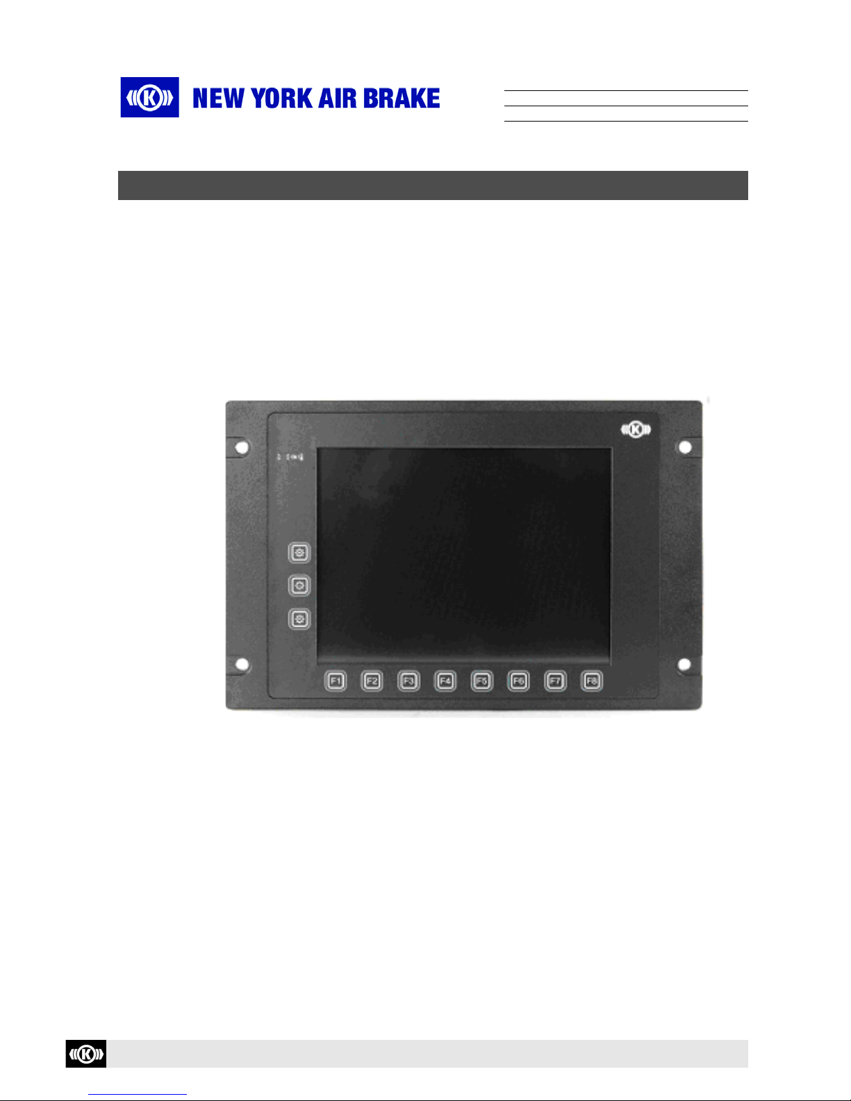
Figure 2-1 Front View of LCDM
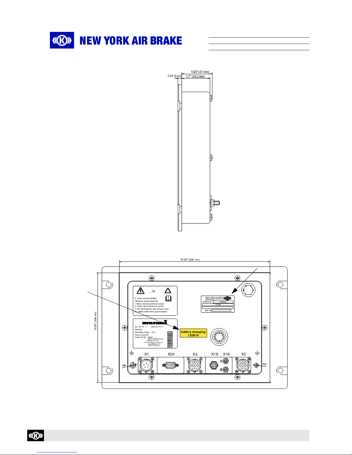
Figure 2-2 Rear View of LCDM (showing nameplate and labels)
2 Product Identification
Nameplate
Battery
Expiration
Decal
Knorr-Bremse Group Page 10 / 40
Copyright 2015© NYAB. All rights reserved, including industrial property rights applications.
NYAB retains any power of disposal, such as copying and transferring.
Locomotive Cab Display Module (LCDM)
Maintenance Manual Doc. No. IP-235
03
Figure 2-3 Side View of LCDM
Figure 2-4 Rear View of LCDM with Externally Mounted Audible Alarm
(showing nameplate and labels)
Nameplate
Battery
Expiration
Decal
Knorr-Bremse Group Page 11 / 40
Copyright 2015© NYAB. All rights reserved, including industrial property rights applications.
NYAB retains any power of disposal, such as copying and transferring.
Locomotive Cab Display Module (LCDM)
Maintenance Manual Doc. No. IP-235
03
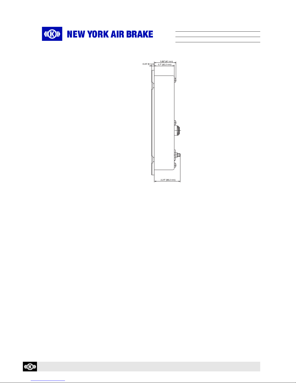
Figure 2-5 Side View of LCDM with Externally Mounted Audible Alarm

Knorr-Bremse Group Page 12 / 40
Copyright 2015© NYAB. All rights reserved, including industrial property rights applications.
NYAB retains any power of disposal, such as copying and transferring.
Locomotive Cab Display Module (LCDM)
Maintenance Manual Doc. No. IP-235
03
3.1 General Safety Awareness
To prevent physical injury or death, all personnel directly or indirectly involved with the ope-
ration of the equipment described in this manual must conform to the following:
3.1.1 Observe all rules and regulations of the railroad where the equipment is being used.
Whenever there is a conflict between the instructions in this manual and the instructions of
the user railroad, the rules and regulations of the user railroad will govern.
3.1.2 When performing any operation of the equipment while it is on the vehicle (on vehicle test,
etc.) special precautions must be taken to ensure that vehicle movement will not occur which
could result in injury to personnel and/or damage to equipment. Make sure the handbrake is
applied and that the wheels are chocked to prevent vehicle from moving.
3.1.3 Shut off power and open airbrake breaker whenever continuity is to be checked or when
handling equipment connections. When shutting off power by means of knife or switch.
3.1.3.1 Attach an approved WARNING tag to the open breaker
3.1.4 Personal eye protection must be worn when doing any work to protect eyes from possible
injury.
3.1.5 Where fasteners removed from the equipment are not satisfactory for reuse, care must be
taken to select replacements that match the originals. Mismatched or incorrect fasteners can
result in equipment damage or malfunction, or possible personal injury.
3 Safety
High Voltages (AC and/or DC) are present. Always exercise extreme
care when working in close proximity to electrically energized appa-
ratus or when making current measurments. To prevent receiving
electrical shock when performing electrical tests, hands must be
clear of electrical components, contacts, and housing. There must
be no bodily contact with the work area.
Failure to comply with these instructions may lead to irreversible
physical injuries which may have fatal consequences.
Ensure that power and/or switches are turned off prior to making any
electrical connections/disconnections.
Failure to comply with these instructions may lead to irreversible
physical injuries which may have fatal consequences.

Knorr-Bremse Group Page 13 / 40
Copyright 2015© NYAB. All rights reserved, including industrial property rights applications.
NYAB retains any power of disposal, such as copying and transferring.
Locomotive Cab Display Module (LCDM)
Maintenance Manual Doc. No. IP-235
03
3.1.6 To ensure the correct functioning of each component, use only the manufacturers genuine
spare parts as replacements.
3.1.7 Appropriate tool selection is required when performing all maintenance operations to avoid
personal injury.
3.1.8 Person(s) having the appropriate job skill level, as governed by the user railroad, are required
when performing maintenance and/or operational tasks with the brake system and system
components.
3.1.9 Whenever a valve or system component is removed from a vehicle for any reason, and it is
reinstalled or replaced with a new or repaired and tested component, a stationary vehicle air
brake test and an equipment test must be performed to ensure that the component functions
properly within the system.
Knorr-Bremse Group Page 14 / 40
Copyright 2015© NYAB. All rights reserved, including industrial property rights applications.
NYAB retains any power of disposal, such as copying and transferring.
Locomotive Cab Display Module (LCDM)
Maintenance Manual Doc. No. IP-235
03
4.1 General
The Locomotive Cab Display Module (LCDM) is used in complex control and guidance
systems as a man-machine interface. It displays process data and receives inputs from the
operator.
Data entry occurs via keyboard designed with 11 function keys (softkeys).
The LCDM is based on a single-board PC ("embedded PC") with a GEODE processor.
An active matrix color display (TFT) is used for the display.
Figure 4-1 Locomotive Cab Display Module (LCDM)
4.2 Features:
• Power supply with galvanically isolated voltage converter (74 VDC or 110 VDC)
• Active Matrix color display (TFT) with background lighting, 640 x 480 pixel, 10.4"
• 4x COM interfaces (RS422 (HDLC supported)
• 1x COM interface RS232 (for service)
• 1x Ethernet interface (10/100 BaseT, with M12 connector, d-coded)
• 2x USB 1.1 interfaces (M8 connector)
• 11 illuminated function keys (softkeys)
• Operating temperature 782340 and 782342: -31° F...+158° F (-35° C...+70° C)
• No moving parts such as fan, hard disks, etc.
• Protection against formation of condensation in the device
4 Product Description

Knorr-Bremse Group Page 15 / 40
Copyright 2015© NYAB. All rights reserved, including industrial property rights applications.
NYAB retains any power of disposal, such as copying and transferring.
Locomotive Cab Display Module (LCDM)
Maintenance Manual Doc. No. IP-235
03
4.3 Electronic Components
4.3.1 Power Supply
The power unit can be adapted to the desired battery voltage with the aid of different DC/DC
converters.
Currently 74 VDC (782340) and 110 VDC (782342) applications are supported.
The device is protected against reverse polarity by the corresponding safety elements as well
as mechanically by a keyed connector.
The device does not have any externally accessible fuses. The device must be replaced if
faulty (see Section 8.4 "Corrective Maintenance" ).
The power consumption of the LCDM is typically 20 W (without heating), maximally 30 W.
4.3.2 TFT Display
The device has a 10.4" TFT display.
The display can portray 640 x 480 pixel with a color depth of 18 bit (262,144 colors) and a
viewing angle of ±60° horizontal and -55° ...+45° vertical to surface normal.
4.3.3 Background Lighting (Display)
Two CCFL tubes are used for the background lighting of the display. The brightness of the
CCFL tubes is controlled by an environment controller. The controller can switch the back-
ground lighting on and off as well as adapt the brightness automatically to the ambient
brightness and simultaneously superpose a manually set brightness value.
The keyboard is illuminated by LEDs.
4.3.4 Optical Sensor
An optical sensor in the front measures the ambient brightness and can adjust the display
background lighting as necessary.
4.3.5 Heating
For heating the device at low ambient temperatures, heaters are located directly on the main
board. When the PC-part is switched on, only one heater can be activated. The heater is
activated automatically by an environment controller.
Knorr-Bremse Group Page 16 / 40
Copyright 2015© NYAB. All rights reserved, including industrial property rights applications.
NYAB retains any power of disposal, such as copying and transferring.
Locomotive Cab Display Module (LCDM)
Maintenance Manual Doc. No. IP-235
03
4.3.6 Status LEDs
Three (3) Status LEDs, are located in the front. The LEDs can be activated from the applica-
tion via envcon daemon. The LED colors are:
Table 4-1 Status LEDs
4.3.7 Audible Alarm
*782340 with Serial Number Prefix prior to "GO" and 782342 with Serial Number Prefix prior
to "HO" have internal audible alarms.
Table 4-2 Overview of Acoustic Signaling Transmitter
4.3.8 System Clock
When powering up the operating system, the system time is synchronized with the time value
of the high-precision RTC of the mainboard.
4.3.9 Keyboard
The LCDM is delivered with 11 softkeys.
Designation Color Function
LED 1 Red Error status (optional)
Freely Available via AP1
LED 2 Yellow Operating state display:
Off – Device is off
On – Device is ready for operation
1 Hz Blinking – Device is outside of operating tem-
perature
4 Hz Blinking – Device off, watchdog limit achieved
LED 3 Blue Freely available via AP1
LCDMs w/Internal Alarm* LCDMs w/External Alarm
Location Mainboard Rear panel
Form Miniature piezoelectric buzzer Miniature piezoelectric buzzer
Volume 85 dB (at 24” (60 cm) distance, free
field)
85 dB (at 24” (60 cm) distance, free field)
Frequency 4 kHz 2.75 kHz

Knorr-Bremse Group Page 17 / 40
Copyright 2015© NYAB. All rights reserved, including industrial property rights applications.
NYAB retains any power of disposal, such as copying and transferring.
Locomotive Cab Display Module (LCDM)
Maintenance Manual Doc. No. IP-235
03
4.3.10 Ethernet
An Ethernet interface according to 10/100BaseT with M12 connector, d-coded, is implemen-
ted. Please observe Section 6.3.1, "Plug-pin Assignment" for a more detailed explanation of
these interfaces.
4.3.11 Four (4) Serial Interfaces RS422/RS485
The serial interfaces are electrically isolated RS422 and capable of sending and receiving
data via HDLC protocol. Please observe Section 6.3.1, "Plug-pin Assignment" for a more de-
tailed explanation of these interfaces.
4.3.12 Serial Interface RS232 (Maintenance)
The RS232 interface is provided for connecting a Service PC. Please observe Section 6.3.1,
"Plug-pin Assignment" for a more detailed explanation of this interface.
4.3.13 USB
There are 2 USB ports for external devices: two interfaces are available via two M8 connec-
tors which fulfill the V1.1 standard and which work with up to 12 MBit/s. For operating systems
without USB support, the Legacy Mode for USB keyboards is supported by the BIOS. Please
observe Section 6.3.1, "Plug-pin Assignment" for a more detailed explanation of this inter-
face.
4.4 Technical Data
4.4.1 Environmental
4.4.1.1 Definition of Temperatures
• Operating temperature:
Air temperature (in max. and min. limits) in the immediate environment of the device, at
which the device is permitted to be operated.
• Storage temperature:
Air temperature (in max. and min. limits) around the device at which the device is per-
mitted to be stored (equipment is isolated from power supply).
• Ambient temperature (in accordance with EN 50155)
1. Outside ambient temperature
2. Temperature inside the cabinet (Device ambient temperature)
3. Temperature of the air surrounding the printed circuit board module (temperature
inside the device).

Knorr-Bremse Group Page 18 / 40
Copyright 2015© NYAB. All rights reserved, including industrial property rights applications.
NYAB retains any power of disposal, such as copying and transferring.
Locomotive Cab Display Module (LCDM)
Maintenance Manual Doc. No. IP-235
03
Figure 4-2 Temperature Ranges According to EN 50155
(using a driver’s console as an example)
4.4.1.2 Operation temperature
782340/782342 -31° F...+158° F (-35° C...+70° C)
4.4.1.3 Storage
Temperature -31° F...+185° F (-35° C...+85° C)
4.4.1.4 Humidity
Humidity in accordance with EN 50155
4.4.1.5 Shock/vibration
Shock/vibration in accordance with EN 50155
4.4.1.6 Fire Protection
Fire Protection in accordance with DIN 5510 Part 2
4.4.2 Mechanical
4.4.2.1 Dimensions
Width 11" (280 mm), with front frame 13.6" (345 mm)
Height 8" (204 mm), with front frame 12.6" (227 mm)
Depth 1.7" (47 mm), with front frame 2" (53 mm)
4.4.2.2 Weight
Weight Approximately 7.49 lbs (3.4 kg, depending on equipment of model)

Knorr-Bremse Group Page 19 / 40
Copyright 2015© NYAB. All rights reserved, including industrial property rights applications.
NYAB retains any power of disposal, such as copying and transferring.
Locomotive Cab Display Module (LCDM)
Maintenance Manual Doc. No. IP-235
03
4.4.2.3 Protection Category
Housing IP54 (with attached wiring and unused plugs covered with a cap)
Front IP65 (when installed)
4.4.2.4 Other
Front Membrane polyester
Display Cover scratch-resistant toughened glass panel,
0.16" (4 mm) thick
The glass panel is inserted flush with the front membrane.
It is an anti-glare design with a glare value of 100.
4.4.3 Electrical
4.4.3.1 Power Supply
4.4.3.1.1 LCDM 782340
Connection reverse polarity protected
Nominal voltage 74VDC (25VDC...135VDC)
Power consumption typ. 20 W (without heating)
max. 30 W
max. starting current 25 A (30 µs.. .-50 µs)
Dielectric strength
Supply voltage primary against secondary / housing: 1,500VAC
Galvanically isolated circuits against housing: 2,000VAC (RS422),
1,000VAC (Ethernet, RS232)
Non galvanically isolated circuits against housing:
due to internal connection between secondary 0V and housing, this dielectric
strength is not given
4.4.3.1.2 LCDM 782342
Connection reverse polarity protected
Nominal voltage 110VDC (66VDC...154VDC)
Power consumption typ. 20 W (without heating)
max. 30 W
max. starting current 25 A (30 µs.. .-50 µs)
Dielectric strength
Supply voltage primary against secondary / housing: 1,500V AC
Galvanically isolated circuits against housing: 2,000V AC (RS422)
1,000V AC (Ethernet, RS232)
Non galvanically isolated circuits against housing:
due to internal connection between secondary 0V and housing, this dielectric
strength is not given.
Knorr-Bremse Group Page 20 / 40
Copyright 2015© NYAB. All rights reserved, including industrial property rights applications.
NYAB retains any power of disposal, such as copying and transferring.
Locomotive Cab Display Module (LCDM)
Maintenance Manual Doc. No. IP-235
03
4.4.3.1.3 Interfaces
Ethernet according to IEEE 802.3 10 Base T
and 100 Base Tx with M12 d-coded
4x serial interfaces according to IEEE RS422
resp. IEEE RS485, HDLC protocol
2x USB according to USB1.1, up to 12 MBit/s
1x serial interface according to IEEE RS232
4.4.3.2 TFT Display
Size 10.4" (visible diagonal measure)
Display Range 8.3" x 6.2" (211.2.mm x 158.4 mm)
Resolution 640 x 480 pixel (VGA)
Number of Colors 262,144 (18 bit)
Pixel Pitch 0.01" x 0.01" (0.33 mm x 0.33 mm)
Viewing Angle Vertical -55° to +45°
Horizontal -60° to +60°
Luminance max 550 nt (550 cd/m2)
(utilixsable 0 nt…
480nt (0 cd/m2…480cd/m2))
Contrast typical: 300:1
Response time typical: tr15 ms
tf35 ms
Design in accordance with ISO 13406-2
4.4.3.3 Audible Alarm
CCOM with Internally Mounted Audible Alarm
Signal Level approx. 85 dB at 24" (60 cm) free field distance
approx. 4 kHz continuous
LCDM with Externally Mounted Audible Alarm
Signal Level approx. 85 dB at 24" (60 cm) free field distance
approx. 2.75 kHz continuous
Table of contents
Other New York Air Brake Monitor manuals


