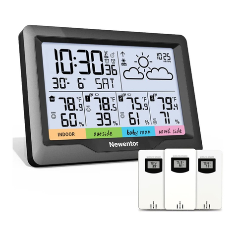
Newentor NT3378 User manual

1
1. WEATHER STATION FEATURES
1.1 Package List ····················································· 2
1.2 Weather Station Appearance ····································· 3
1.3 Button Functions ················································· 6
2. INITIAL OPERATION ········································ 7
3. BACKLIGHT SETTING ······································ 8
4. TIME, TIME ZONE AND CALENDAR SETTING
4.1 Manual Time Setting ············································· 8
4.2 Automatic Time Setting ·········································· 9
5. DAILY ALARM AND SNOOZE FUNCTION SETTING
5.1 Setting the Daily Alarm ··········································· 9
5.2 Switching On/Off the Alarm Signal ······························· 9
5.3 Snooze Function ·················································· 9
6. WEATHER FORECAST AND BAROMETRIC
6.1 Weather Forecast ················································ 10
6.2 Barometric Pressure Display ····································· 10
6.3 Barometric Trend Display ······································· 11
7. LUNAR PHASES AND TIDE INDICATOR ·············· 11
8. TEMPERATURE, HUMIDITY AND COMFORT DISPLAY
8.1 °C or °F Temperature Display ····································· 12
8.2 Current Temperature and Temperature Trend Display ··········· 12
8.3 Outdoor Temperature Alert Settings ····························· 12
8.4 Activating and Deactivating Temperature & Frost Alert ·········· 12
8.5 Comfort Display ·················································· 13
8.6 Current Humidity and Humidity Trend Display ···················· 13
8.7 Maximum/Minimum Temperature and Humidity ·················· 13
8.8 Remote Sensor Transmission ····································· 14
9. USB CHARGER ·············································· 14
10. LOW BATTERY ············································ 14
11. PRODUCT SPECIFICATION ····························· 15
TABLE OF CONTENTS

EN - Weather Station
2
1.1 Package List
01 WEATHER STATION
FEATURES
ITEM NO.
1
2
3
4
5
1
1
1
1
1
PART NAME FIGURE QTY
Weather Station
Outside Sensor
Power Charger
User Manual
Button Function
Manual

3
1.2 Weather Station Appearance
A10
A14
A13
A12
A11
A7
A8
A5
A4
A3
A2
A1
A6
A9
Part A – Weather Station Front
A1: Remote Battery Signal ( 14th page)
A2: Remote Temperature ( 15th page)
A3: Remote Humidity ( 15th page)
A4: Remote Temperature Alert ( 12th page)
A5: Radio Mast Icon, DST, Time/Calendar or Alarm Time( 7-9th page)
A6: Outside Channel ( 14th page)
A7: Weather Forecast ( 10th page)
A8: Moon Phase ( 11th page)
A9: Barometric Trend ( 11th page)
A10: Barometric Pressure ( 10th page)
A11: Indoor Temperature ( 15th page)
A12: Indoor Comfort ( 13th page)
A13: Indoor Humidity ( 15th page)
A14: Histogram Shows the Atmospheric Pressure( 11th page)
There may be ±1℃/1.8℉ deviation when temperature is 0℃~40 ℃/32
℉~104℉, while ±2℃/3.6℉ deviation in other ranges.
There may be ±5% deviation when humidity is 40%~80%, while ±8%
deviation in other ranges.

4
Part B – Weather Station Back
B1: “ ” Touch Field ( 6th page )
B2: “ ” Button ( 8th page )
B3: “ ” Button ( 9th page )
B4: “ ▲” Button ( 6th page )
B5: “ ▼” Button ( 6th page )
B6: “ ” Button ( 12th page )
B7: “ ” Button ( 8th,10th page )
B8: “ MEM ” Button ( 6th page )
B9: Alarm On/Off Shift Switch ( 9th page )
B10: USB Charger Output Socket ( 14th page )
B11: Power Supply Socket
B12: Station Table Stand
B13: Battery Compartment
When plugged in, press “ ” button to keep the backlight always on or
adjust brightness.
When the clock is synchronizing the WWVB signal, only “ ” and “▲”
buttons work. The backlight is only on for 15 seconds by pressing “ ”
button, this process lasts about 7 minutes and the backlight will light up
again after synchronization. Press “▲” button to exit from the WWVB signal
search mode.
B12
B13

5
Part C – Wireless Outdoor Sensor
C1
C5
C2
C3
C4
C6
C9
C7
C8
C10
5
C1: Remote Sensor – Temperature
C2: Remote Transmission Signal
C3: Remote Channel ( 14th page)
C4: Transmit Signal LED
C5: Remote Sensor – Humidity
C6: “ °C/°F ” Switch Button
C7: “TX” Reset Button ( 14th page )
C8: 3 Channels Select ( 14th page )
C9: Remote Wall Mount Hole
C10: Battery Compartment
To get accurate readings, please keep the main unit clear of any unusual
source of heat or cold (such as lamps, heaters and others) and that the
sensor is also protected from direct sunlight, rain, or the heat it may
experience from being mounted on a warm wall, or from heat rising from a
surface below it.

6
1.3 Button Function
Button
Function Normal
Mode
Switch
Display
of
Calendar
or
Second
°C/°F
Switch
3 Channel
Switch
Turn
On/Off
Tempera-
ture Alert
Time
Setting
Automatic
Time
Setting
Channel
Searching
Outdoor
Tempera
ture Alert
Setting
Confirm
and Go to
the Next
Step
///////
/
/
/ / / / / / / /
Increase
Decrease
Increase
Decrease
Increase
Continually
Decrease
Continually
Increase
Continually
Decrease
Continually
Increase
Decrease
Increase
Continually
Decrease
Continually
Go to
the Next
Step
Back to
the Last
Step
Time
Setting
Alarm
Setting
HoldHoldHoldHold
Outdoor
Temperature
Alert Setting
PressPressPressPressPress Hold
Weather
Forecast
Setting
▲
▲
B2
B4
B5
Switch
Display
of
Calendar
or Alarm
Alarm
Setting
/ / / / / / /
B3
B6
Clear
Max/Min
Data
/ / / / / / / /
MEM
B8
B9
Adjust
Brightness
of the
Backlight
in DC
Mode
Weather
Forecast
Setting
/ / / / / //
Confirm
Setting
B7
Backlight
On for 15
Seconds
Backlight
On for 15
Seconds
Backlight
On for 15
Seconds
Backlight
On for 15
Seconds
Backlight
On for 15
Seconds
Backlight
On for 15
Seconds
Backlight
On for 15
Seconds
Backlight
On for 15
Seconds
/ /
B1
Slide up to switch On alarm, slide down to switch Off alarm.
View
Max/Min
Data
indoor/
outdoor
Confirm
and Go to
the Next
Step

7
· Plug in the original power cord or insert 2 x AA batteries observing polarity [
“+" and “-" marks]. All icons on the screen of main unit will light up for 3
seconds, you will hear a beep, and the main unit will begin to detect the indoor
temperature and humidity.
·Open the cover of remote sensor, choose a channel for remote sensor(1, 2 or
3, and press “▼" button to set the channel of the main unit match to the
remote sensor's), insert 2 x AA batteries observing polarity [ “+" and “-"
marks], then the remote sensor will begin to detect the temperature and
humidity. The LED light flashes once indicating that the remote sensor sends a
wireless signal once.
·After the indoor temperature and humidity detection is completed, the main
unit will begin to establish a connection with the remote sensor (note: please
keep the channel of the main unit and remote sensor consistent). At this
time, the RF icon “ " will appear and flash in the “REMOTE SENSOR" display
area of the main unit.
·Once the weather station has established a connection to the remote sensor,
it will automatically begin to search for WWVB signals to set the time and date
(at this time, to prevent the radio clock signal from being interfered with, the
backlight will turn dark. The default time zone is Pacific Time -8, if you need
to select the time zone that matches your location, press “▲” button to exit
from WWVB signal search mode, then refer to page 8 to set the time zone
and time). At this time, the radio mast icon “ " will flash (the icon is next to
the digital display of time) and the screen will turn dark, this process takes
about 7 minutes.
F.Y.I
·The main unit can be connected to 3 remote sensors at the same time,
please make sure that the channels of the remote sensors are different.
·In the process of searching for WWVB signal, the radio mast icon “ " will
appear and the screen will turn dark, at this time, only “ ” and “▲”but-
tons can work. You can press “ " button to light up the screen for 15
seconds and press “▲” button to stop searching WWVB signal.
·When radio mast icon shows as “ ", it means WWVB is strong, when radio
mast icon shows as “ " , it means WWVB signal is weak.
·To get a strong WWVB signal, we suggest that:
--A minimum distance of 8 feet to all sources of interference, such as
televisions or computer monitors.
--Radio reception is weaker in rooms with concrete walls (e.g.: in cellars) and
in offices. In such circumstances, place the device close to the window.
02 INITIAL
OPERATION

8
·When powered by batteries, to save power, the backlight is only on for 15
seconds by pressing “ ".
·When plugged in the power cord, the backlight brightness button is “ "
button, right side. Press it to turn on the backlight full brightness. Press it again
to begin dimming the light. Keep pressing. When the display gets to full dark,
you can turn it back on for 15 seconds using “ " button. To get back to
continued full brightness, press “ " button again.
03
04 TIME, TIME ZONE AND
CALENDAR SETTING
4.1 Manual Time Setting
BACKLIGHT
SETTING
· Press and hold “ ” button for about 2 seconds to enter the time setting
operation, press “▲” and “▼” buttons to select, press “ ” button to confirm
and go to the next step. The sequence steps are as follows.
◇ 12/24 Hour Format
◇ Time Zone
◇ DST Switch
◇ Hour
◇ Minute
◇ Month/Date Format
◇ Year
◇ Month
◇ Date
For example, press and hold “ ” button for about 2 seconds, the 12/24 Hour
Format display begins to flash, press“▲” and“▼” buttons to set the 12/24
hour mode you prefer, press “ ” button to confirm and the Time Zone
begins to flash.
F.Y.I.
· During operation, if no operation is performed within 20 seconds, the device
will return to normal mode automatically.
·The time zone must be selected correctly according to your location, or the
time/date will be synced incorrectly after searching WWVB signal.

9
5.2 Switching ON/OFF the Alarm Signal
·When the alarm shift switch is pushed in the “ ” position, the “ ” icon
will appear next to the date, the alarm function is ON.
·When the alarm shift switch is pushed in the “ ” position, the “ ” icon
will disappear, the alarm function is OFF.
· When the alarm goes off, press any button except the “ ” button to
stop the alarm signal. It is not necessary to reactivate the alarm,the alarm
clock will ring again at this time next day.
5.3 Snooze Function
· When the alarm goes off, press the “ ” button, the alarm clock enters
SNOOZE mode, the alarm will go off again in 5 minutes.
5.1 Setting the Daily Alarm
· Press “ ” button to switch the display calendar or alarm.
·Press and hold “ ” button for 2 seconds, the Alarm Time hour display
begins to flash, press “▲” and “▼” buttons to set the required hour.
· Press “ ” button to confirm your setting, the Minute display begins to flash,
press “▲” and “▼” buttons to set the required minute.
· Press “ ” button to confirm your setting and return to normal mode.
05 DAILY ALARM AND SNOOZE
FUNCTION SETTING
· Before searching Radio signal (WWVB signal), choose a right Time Zone
according to your location.
·After the main unit is connected to the remote sensor,the main unit will start
to search WWVB signal and the radio mast icon starts to flash. If the signal is
weak, the icon will be showed as “ ” , if the signal is strong, the icon will be
showed as “ " . This process lasts up to 7 minutes. If the signal is not
received successfully, the system will automatically attempt another synchroni-
zation at the next full one hour. If the reception is successful, this step will not
be performed.
·At every 1:00/2:00/3:00 am, the clock will carry out the synchronization
procedure with the WWVB signal to correct any deviations to the exact time
automatically. If fail, the system will automatically attempt another synchroni-
zation at the next full one hour.
·To start searching WWVB signal manually, choose a time zone and return to
normal mode first, then press and hold “▲" button more than 3 seconds.
·During WWVB signal searching , only “ ” and “▲” button work, other
buttons do not work and backlight will turn dark. If you want to carry out other
operations, press “▲” button to exit this process.
4.2 Automatic Time Setting

10
6.2 Barometric Pressure Display
·Press and hold “ ” button for 2 seconds to enter barometric unit and
weather settings. Press “▲” and “▼” buttons to set the barometric unit to
display in the “hPa/mb" or“inHg".
· Press “ ” to confirm your setting, the weather symbol begins to flash,
press “▲” and “▼” buttons to choose the current weather symbol.
· Press “ ” button to confirm your setting and return to normal mode.
·If the barometric pressure reading is below the minimum range, “LLLL”will be
displayed on the screen. If the barometric pressure reading is above the
maximum range, “HHHH”will be displayed on the screen.
· Barometric values are related to the temperature and humidity of the
environment and cannot be modified manually.
·The weather station displays the following weather symbols:
Sunny Slightly Cloudy Cloudy Rainy Heavy Rainy Snowy
6.1 Weather Forecast
06 WEATHER FORECAST AND
BAROMETRIC
· The device calculates a weather forecast for the next 12-24 hours based
on the barometric pressure trend, NOT the current weather.
·Of course this forecast can’t compare to that of professional weather
services supported by satellites and high performance computers, but merely
provides an approximate indication of current developments. Please give priority
to the weather forecast of the local weather forecast service.
·It usually takes about 7 to 10 days for barometric calibration as it will ensure
an accurate forecast for your location. When using the device for the first time,
please wait a few days to correct the weather forecast. To speed up device
response and measurement time, you can also manually calibrate the current
weather icon. Step refer to 6.2 Barometric Pressure Display.
F.Y.I.
· The flashing clouds indicate that the system is operating normally, not that
the product is malfunctioning.
·The snowy weather forecast icon only appears when the outside temperature
is -4 ℃ / 24.8℉.

11
· The device displays 12 different moon phases according to the calendar.
During the new moon, the moon phase screen won't light up until Waxing Moon.
Waxing
half-moon
Waxing full
moon
Full
moon
Waning full
moon
Waning
half-moon
Half-moonHalf-moon
New
moon
07 LUNAR PHASES AND TIDE
INDICATOR
It is normal for the barometric histogram to move continuously from right to
left, which means it is working.
TREND
TREND
TREND
6.3 Barometric Trend Display
The barometric pressure continued to rise more than 1 hPa within 1
hour.
The cumulative value of the barometric pressure rising or falling
continuously does not exceed 1 hPa within 1 hour.
The barometric pressure continued to drop more than 1 hPa
within 1 hour.

12
·When the temperature of the remote sensor exceeds the set temperature
range, the alert alarm will be activated and sound for 5 seconds, at the same
time, the temperature alert icon “ " , temperature value and alarm upper limit
icon “ ”or lower limit icon “ ” will all flash.
·When the temperature of remote sensor is +30°F to + 37°F or –1°C to + 3°C,
the frost alarm will be activated, “ ” icon will flash.
8.1 °C or °F Temperature Display
08 TEMPERATURE, HUMIDITY
AND COMFORT DISPLAY
· Press “▲” button to change the temperature unit to °C or °F.
8.2 Current Temperature and Temperature
Trend Display
·Press and hold the “ ” button for 2 seconds,the icon of Upper limit of the
Temperature alarm “ ” begins to flash. Press the “▲” and “▼” buttons to
set the required maximum temperature. Press “ ” to confirm your setting.
·The icon of the Lower limit of the Temperature alarm “ ” starts to flash.
Press the “▲” and “▼” buttons to set the required minimum temperature. Press
“ ” button to confirm your setting and return to normal mode.
8.3 Outdoor Temperature & Frost Alert
Settings
· Before entering the settings, you must select the remote channel, different
channels can set different temperature alarm ranges.
F.Y.I.:
· Press “ ” button to activate or deactivate the remote temperature alert.
When the remote temperature alarm is activated, the temperature alarm icon
will be displayed in the REMOTE SENSOR window.
8.4 Activating and Deactivating Temperature
& Frost Alert
The temperature continued to rise more than 1℃/1.8℉ within 1 hour.
The cumulative value of the temperature rising or falling continuously
does not exceed 1℃ & 1.8℉ within 1 hour.
The temperature continued to drop more than 1℃/1.8℉ within 1 hour.

13
Comfortable too cold or too hot
8.5 Comfort Display
· Indoor comfort level is calculated according to the indoor temperature and
humidity, there are 5 levels.
8.6 Current Humidity and Humidity Trend
Display
The humidity continued to rise more than 5% within 1 hour.
The cumulative value of the humidity rising or falling continuously
does not exceed 5% within 1 hour.
The humidity continues to drop more than 5% within 1 hour.
8.7 Maximum/Minimum Temperature and
Humidity
· To view indoor/outdoor maximum/minimum temperature and humidity data in
the past 24 hours, press the “MEM” button.
◇ Once to show the maximum temperature and humidity values.
◇ Twice to show the minimum temperature and humidity values.
◇ Three times to return to the current temperature and humidity levels.
·Press and hold “MEM” button for about 2 seconds to clear and re-record the
maximum and minimum temperature and humidity.
F.Y.I.:
·If the temperature reading is below range, the “LL.L” will be displayed. If the
temperature reading is above range, the “HH.H” will be displayed.

14
8.8 Remote Sensor Transmission
·When the batteries are installed in the remote sensor, the main unit will
automatically connect to it.
·The main unit can connect up to 3 remote sensors at the same time, please
make sure that the channels of the remote sensors are different.
· “▼” button is the channel select button, keep pressing “▼” button, the
screen displays CH1, CH2, CH3, CYCLE mode(there is a cycle symbol “ ”
displayed next to CH, at this time, the screen will cyclically display the readings
of CH1, CH2, and CH3 every 5 seconds), press “▼” button again to back to
CH1.
· Press and hold “▼" button for 3 seconds to manually connect the remote
sensor, in the meantime, press the “TX" button of remote sensor to speed up
connection.
F.Y.I.:
·When a channel is not connected to the remote sensor, the readings of this
channel will display “--".
·There is only 1 remote sensor included, please make the main unit stay in the
same channel with remote sensor.
·If the battery icon “ ” appears, the batteries in the outdoor sensor
should be replaced as soon as possible.
· When you use USB charger to charge the electronic device, please make sure
weather station is powered by original power cord, DO NOT use batteries only.
09 USB
CHARGER
10 LOW
BATTERY

15
·LED screen size: 7.5 inches
·Indoor temperature measurement range: 15°F (-9.9°C) to 122°F (50°C)
·Outdoor temperature measurement range: -4°F (-20°C) to 140°F (60°C)
Temperature unit: °F or °C
·Indoor & Outdoor humidity measurable range: 20%RH ~ 95%RH
·Barometric pressure measurement range: 600 hPa/mb(17.72 inHg) to1100
hPa/mb (32.48 inHg)
·Remote receiving range
--433.92MHz RF transmitting frequency
--200 feet transmission range in an open area
·Power supply
--Main unit : 2 x AA (not included) or Power Adapter (included)
--Remote sensor: 2 x AA (not included)
·Temperature and humidity detection cycle
—Main unit: 60S
—Remote sensor update time: CH1: 68S, CH2: 72S, CH3: 76S
·The default setting of the temperature alert
--The upper limit: 140℉/60℃
--The lower limit: -4℉/-20℃
11 PRODUCT
SPECIFICATION

16
SAFETY
◆ This device is not intended for use by persons (including children under 8 years
of age) with reduced physical, sensory or mental capabilities, or lack of experience
and knowledge unless they have been given supervision or instruction by the person
responsible for their safety.
◆The weather station does not include batteries, but is a battery-operated product.
If a battery is swallowed accidentally, seek medical assistance immediately.
RISK OF BATTERY LEAKAGE
◆ In the event of a battery leak, immediately remove it from the device.
◆ If battery acid is accidentally contacted, rinse thoroughly with water immediately
and seek medical assistance immediately.
◆ Only use the same type of batteries, do not mix used and new batteries.
◆ Avoid using the device under extreme environmental conditions and temperatures.
◆ Remove the batteries from the device if they have not been used for a long
period.
RISK OF EQUIPMENT DAMAGE
◆If necessary, clean the battery and device contacts before inserting the battery.
◆Remove drained batteries from the product as soon as possible .
◆Please do not make any changes to this item. Repairs are only allowed in
professional repair shops. Incorrect maintenance will seriously endanger user safety.
GUARANTEE
◆The device has been manufactured in accordance with strict quality guidelines
and has been inspected carefully before delivery.
◆Newentor guarantees that the warranty period of this device is 1 year from the
date of purchase.

17
DECLARATION OF CONFORMITY
◆This product was manufactured in accordance with the harmonized European
standards, you will find the declaration of conformity below:
◇2014/30/EU EMC Directive
◇2014/53/EU RED Directive
◇2011/65/EU RoHS Directive
The packaging is made of environmentally friendly materials, which
may be disposed through your local recycling facilities.
When your device has come to the end of its life, in the interest of
environmental protection please do not throw it out with your
household refuse, but take it to a suitable center where is can be
disposed of properly.
All batteries must be handed in at a collection point in your
community, suburb, or at the retailer. Such batteries can thus be
disposed of in an environmentally friendly way.
DISPOSAL
Table of contents
Other Newentor Weather Station manuals
Popular Weather Station manuals by other brands

La Crosse Technology
La Crosse Technology WS-2310 Quick setup manual

Holman
Holman iWeather WS2813A instruction manual

WEATHER DIRECT
WEATHER DIRECT Weather Direct WD-3303 owner's manual

National Geographic
National Geographic 331NC manual

La Crosse Technology
La Crosse Technology WS-9400U manual

La Crosse Technology
La Crosse Technology ED31411 Quick setup guide