Newland NLS-EVK3030 User manual

NLS-EVK3030
Software Development Board
User Guide

-
2 -
Revision History
Version
Description
Date
V1.0.0
Initial release.
September 12, 2016
V1.0.1
Updated the pictures and relevant texts.
October 12, 2017
V1.0.2
Added an example of cable installation (EM2096).
February 8, 2018
V1.0.3
Updated relevant texts.
February 27, 2018
V1.0.4
Updated Pinout of J1 and Pinout of J2 sections.
June 04, 2020

Table of Contents
Revision History........................................................................................................................................- 2 -
About This Guide ..........................................................................................................................................1
Introduction ...............................................................................................................................................1
Chapter 1 Electrical Specifications..............................................................................................................2
EVK3030 Schematic Diagram...................................................................................................................2
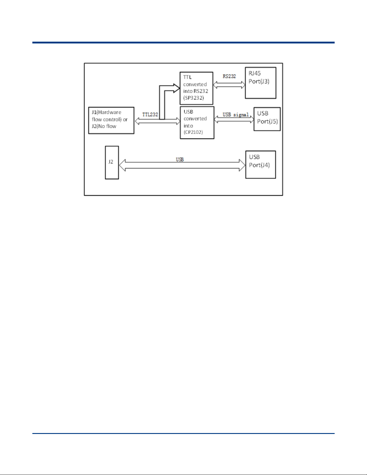
EVK3030 Block Diagram...........................................................................................................................3
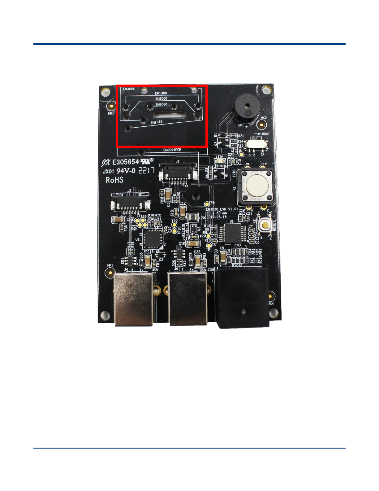
Parts Placement Layout............................................................................................................................4
Scan Engine Port Pinouts .........................................................................................................................6
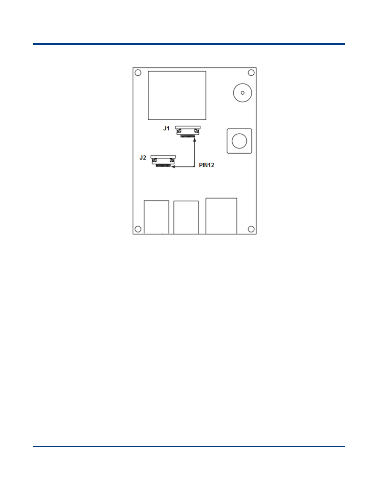
Pinout of J1.........................................................................................................................................7
Pinout of J2.........................................................................................................................................8
12-pin FFC Cable Installation....................................................................................................................9
EVK3030 Circuit Diagram ....................................................................................................................... 11
Operating Instructions.............................................................................................................................12
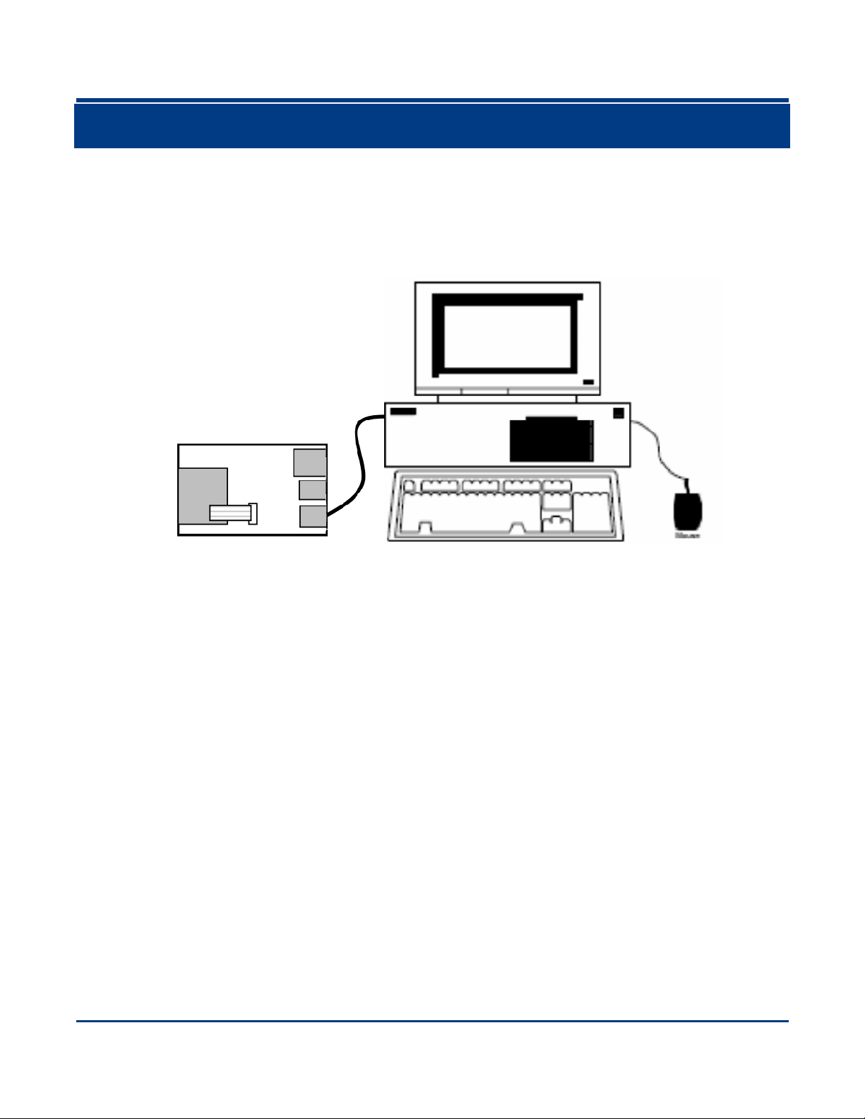
Connecting EVK3030 to PC via J3.................................................................................................... 12
Connecting EVK3030 to PC via J4.................................................................................................... 12
Connecting EVK3030 to PC via J5.................................................................................................... 12

-
4 -

1
About This Guide
Introduction
This manual provides instructions on how to use NLS-EVK3030 software development board (hereinafter
referred to as “EVK3030”). EVK3030 is an upgrade of EVK3000 V2 with an additional USB port via which
users can enjoy the USB feature of the scan engine connected. For more details about scan engines
which EVK3030 is applicable to, please ask the technical support for the scan engine supporting table.

2
Chapter 1 Electrical Specifications
EVK3030 Schematic Diagram

3
EVK3030 Block Diagram
1. Place a scan engine on EVK3030.
2. Connect the scan engine to EVK3030 with a 12-pin FFC cable.
3. Connect EVK3030 to PC.

4
Parts Placement Layout
LED
Engine
Buzzer
Trigger
Reset
J1
J2
J3
J4
J5

5
Part
Description
Note
J1
TTL-232 scan engine port
Connect J3 or J5 to a host device.
J2
TTL-232/USB scan engine port
Connect J3 or J4 or J5 to a host device.
J3
RJ45 port
Connect J1 or J2 to a scan engine using TTL-232
signals. EVK3030 converts TTL-232 signals of
scan engine into RS-232 signals. EVK3030 only
can communicate with COM tools on host device.
J4
USB-A port
Connect J2 to a scan engine using USB signals.
EVK3030 can communicate with host device
through USB HID port and USB COM emulation.
J5
USB-B port, TTL-232 to USB
Connect J1 or J2 to scan engine using TTL-232
signals.
EVK3030 converts TTL-232 signals of scan engine
into USB signals. EVK3030 only can communicate
with USB virtual COM on host device.
LED
LED
(Good Read LED output)
Red LED will flash when the barcode reading is
done.
Buzzer
Buzzer (Good Read/Power On
beeper output)
The Beep sound will occur when the scan engine is
powered on or the barcode reading is done.
Trigger
Trigger
(Trigger signal input)
Barcode reading can be conducted through
control over the trigger signal.
Reset
Reset Button
(Reset signal input)
Reset signal input. Keep the low level above 100us
to reset the scan engine.
Engine
Space for placing scan engine
It is used for placing and fixing the scan engine.

6
Scan Engine Port Pinouts

7
Pinout of J1
PIN
Signal
Function
1
BOOT
It is connected to the DIP Switch. Put the switch on the right where
EVK3030 is set as the low level. Under such circumstance, it will enter the
Boot downloading mode. If it connects to the PIN of the scan engine which
is NC, there will be no such function and DIP switch will be invalid.
2
VCC
3.3V power supply.
3
GND
Power-supply ground.
4
RXD
RXD signal led out via the EVK3030 connects to the PIN (RXD) of the scan
engine.
5
TXD
TXD signal led out via the EVK3030 connects to the PIN (TXD) of the scan
engine.
6
CTS
Clear to send.
7
RTS
Request to send.
8
-
Not connected.
9
BUZ
Beeper output.
10
LED
Good Read LED output.
11
nWake
Reset signal input. The PIN is conneted to the Key K2 (reset). Press the
Key K2 (reset), and EVK3030 will enter the low level state. Keep the low
level above 100 us to reset the scan engine.
12
nTrig
Trigger signal input.

8
Pinout of J2
PIN
Signal
Function
1
-
Not connected.
2
VCC
3.3V power supply.
3
GND
Power-supply ground.
4
RXD
RXD signal led out via the EVK3030 connects to the PIN (RXD) of the scan
engine.
5
TXD
TXD signal led out via the EVK3030 connects to the PIN (TXD) of the scan
engine.
6
USB-
USB D- differential data signal.
7
USB+
USB D+ differential data signal.
8
-
Not connected.
9
BUZ
Beeper output.
10
LED
Good Read LED output.
11
nWake
Reset signal input. The PIN is conneted to the Key K2 (reset). Press the
Key K2 (reset), and EVK3030 will enter the low level state. Keep the low
level above 100 us to reset the scan engine.
12
nTrig
Trigger signal input.

9
12-pin FFC Cable Installation
The example below shows how the EM2096 scan engine should be connected to the EVK3030.

10

11
EVK3030 Circuit Diagram

12
Operating Instructions
Connecting EVK3030 to PC via J3
1. Connect J1 or J2 on EVK3030 to scan engine supporting TTL-232 port.
2. Connect J3 on EVK3030 to the serial port on PC with RS-232 cable (CBL037R).
3. Plug the power adapter (KSAS0120500150D5) into the power connector on the RS-232 cable.
4. Plug the power adapter into AC outlet.
5. When EVK3030 is electrified, its buzzer will beep, which means EVK3030 is in working state.
6. Press the trigger and start to read barcodes.
Connecting EVK3030 to PC via J4
1. Connect J2 on EVK3030 to scan engine supporting USB port.
2. Connect J4 on EVK3030 to the USB port on PC with USB cable (FM300U).
3. When using USB HID-KBW, no driver is required; when using USB COM Port Emulation, install the
corresponding driver (UFCOM driver) on PC.
4. When EVK3030 is electrified, its buzzer will beep, which means EVK3030 is in working state.
5. Press the trigger and start to read barcodes.
Connecting EVK3030 to PC via J5
1. Install CP210x driver on PC.
2. Connect J1 or J2 on EVK3030 to scan engine supporting TTL-232 port.
3. Connect J5 on EVK3030 to the USB port on PC.
4. When EVK3030 is electrified, its buzzer will beep, which means EVK3030 is in working state.
5. Press the trigger and start to read barcodes.

Newland Auto-ID Tech. Co., Ltd. (Headquarter)
Add: No.1, Rujiang West Rd., Mawei, Fuzhou, Fujian 350001, China
Tel: +86 (0) 591 8397 9500
Fax: +86 (0) 591 8397 9216
Web: www.newlandaidc.com
Newland APAC
Newland Taiwan Inc.
Add: 7F-6, No. 268, Liancheng Rd., Jhonghe Dist. 235, New Taipei City, Taiwan
Tel: +886 2 7731 5388
Fax: +886 2 7731 5389
Web: www.newland-id.com.tw
Newland Japan
Tel: +886 2 7731 5388 ext. 71
Web: www.newlandaidc.com/jp/
Newland Korea
Add: Biz. Center Best-one, Jang-eun Medical Plaza 6F, Bojeong-dong 1261-4,
Kihung-gu, Yongin-City, Kyunggi-do, South Korea
Tel: +82 10 8990 4838
Fax: +82 70 4369 0009
Web: www.newlandaidc.com/kor/
Newland India
Add: 814, Tower B, NOIDA ONE business park B-8, Sector 62, Noida, Uttar
Pradesh-201301
Tel: +91 120 7964266
Web: www.newlandaidc.com
Newland EMEA
Newland Europe BV
Add: Rolweg 25, 4104 AVCulemborg, The Netherlands
Tel: +31 (0) 345 87 00 33
Fax: +31 (0) 345 87 00 39
Web: www.newland-id.com
Newland NALA
Newland North America Inc.
Add: 46559 Fremont Blvd., Fremont, CA 94538, USA
Tel: +1 510 490 3888
Fax: +1 510 490 3887
Web: www.newlandamerica.com
Newland Latin America
Tel: +1 (239) 598 0068
Fax: +1 (239) 280 1238
Web: www.newlandamerica.com
Newland Auto-ID Tech. Co., Ltd.
Other manuals for NLS-EVK3030
1
Table of contents
Other Newland Motherboard manuals