Newland NLS-EVK3030 User manual

NLS-EVK3030
Software Development Board
User Guide

Revision History
Version
Description
Date
V1.0.0
Initial release.
September 12, 2016
V1.0.1
Updated the pictures and relevant texts.
October 12, 2017
V1.0.2
Updated the pictures and relevant texts. Added an example of cable
installation (EM2096).
February 28, 2018

Table of Contents
Revision History.......................................................................................................................................... - 2 -
Introduction.......................................................................................................................................................1
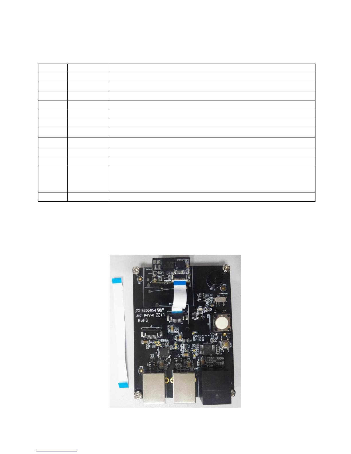
Parts Placement Layout ..................................................................................................................................1
EVK3030 Block Diagram..................................................................................................................................3
Scan Engine Port Pinouts ...............................................................................................................................4
Pinout of J1..................................................................................................................................................4
Pinout of J2..................................................................................................................................................5
12-pin FFC Cable Installation..........................................................................................................................5
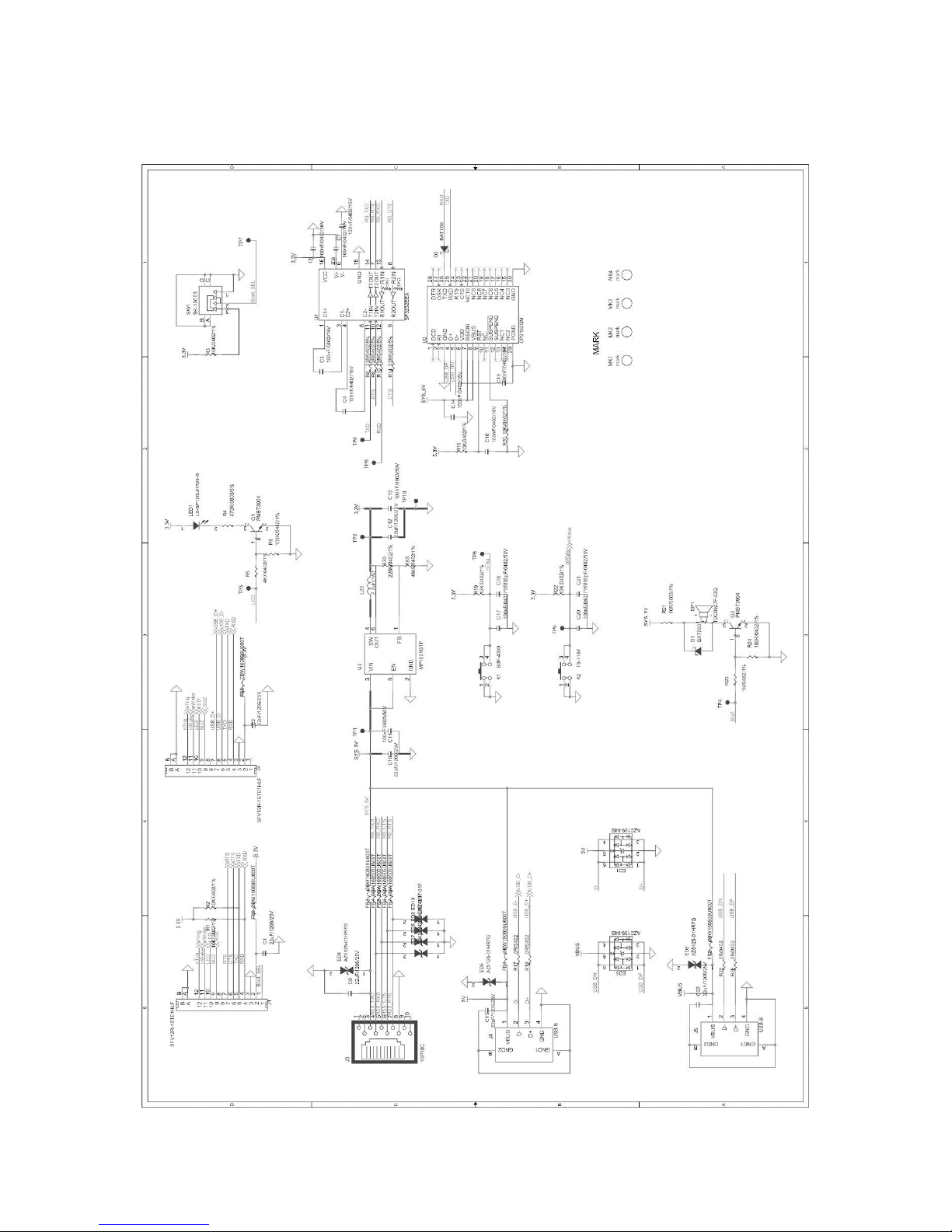
EVK3030 Circuit Diagram................................................................................................................................7
Operating Instructions.....................................................................................................................................8
Connecting EVK3030 to PC via J4..............................................................................................................8
Connecting EVK3030 to PC via J5..............................................................................................................8
Connecting EVK3030 to PC via J3..............................................................................................................8

1
Introduction
This manual provides instructions on how to use NLS-EVK3030 software development board (hereinafter
referred to as “EVK3030”). EVK3030 is an upgrade of EVK3000V2 with an additional USB port via which
users can enjoy the USB feature of the scan engine connected. For more details about scan engines
which EVK3030 is applicable to, please ask the technical support for the scan engine supporting table.
Parts Placement Layout
LED
Engine
Buzzer
Trigger
Reset
J1
J2
J3
J4
J5
Switch

2
Part
Description
Note
J1
TTL-232 scan engine port
Connect J3 or J5 to a host device.
J2
TTL-232/USB scan engine port
Connect J3 or J4 or J5 to a host device.
J3
RJ45 port
Connect J1 or J2 to a scan engine using TTL-232
signals. EVK3030 converts TTL-232 signals of
scan engine into RS-232 signals. EVK3030 only
can communicate with COM tools on host device.
J4
USB-B port
Connect J2 to a scan engine using USB signals.
EVK3030 can communicate with host device
through USB HID or USB COM emulation.
J5
USB-B port, TTL-232 to USB
Connect J1 or J2 to scan engine using TTL-232
signals.
EVK3030 converts TTL-232 signals of scan engine
into USB signals. EVK3030 only can communicate
with USB virtual COM on host device.
LED
LED
(Good Read LED output)
The red LED will flash when a barcode is decoded.
Buzzer
Buzzer (Good Read/Power On
beeper output)
The buzzer will beep when the scan engine is
powered on or a barcode is decoded.
Trigger
Trigger
(Trigger signal input)
Barcode reading can be conducted by pressing the
trigger.
Reset
Reset Button
(Reset signal input)
Pressing the Reset button will reset the scan
engine.
Engine
Space for placing scan engine
It is used for placing and fixing the scan engine.
Switch
DIP switch
For the details, refer to the “Pinout of J1” section.

3
EVK3030 Block Diagram
RS232
TTL232 USB
USB
TTL to RS232
(SP3232)
TTL to USB
(CP2102)
RJ45 Port
(J3)
USB Port
(J5)
USB Port
(J4)
J1 (Hardware flow
control) or
J2 (No flow control)
J2
1. Place a scan engine on EVK3030.
2. Connect the scan engine to EVK3030 with a 12-pin FFC cable.
3. Connect EVK3030 to PC.

4
Scan Engine Port Pinouts
Pinout of J1
PIN
Signal
Function
1
BOOT
It is connected to the DIP Switch on the EVK3030. If the switch is put in the
BOOT position (see the picture in the “Parts Placement Layout” section),
where this pin is set at low level, then the engine connected enters the Boot
downloading mode. If this pin is connected to the PIN of the scan engine
which is NC, then the DIP switch does not function.
2
VCC
3.3V power supply.
3
GND
Power-supply ground.
4
RXD
TTL level 232 receive data.
5
TXD
TTL level 232 transmit data.
6
CTS
Clear to send.
7
RTS
Request to send.
8
-
Not connected.
9
BUZ
Beeper output.
10
LED
Good Read LED output.
11
nWake
Reset signal input. This PIN is conneted to the Reset button on the
EVK3030. Holding down the button for over 100 us (this pin is set at low
level) will reset the scan engine connected.
12
nTrig
Trigger signal input.

5
Pinout of J2
PIN
Signal
Function
1
-
Not connected.
2
VCC
3.3V power supply.
3
GND
Power-supply ground.
4
RXD
TTL level 232 receive data
5
TXD
TTL level 232 transmit data.
6
USB-
USB D- differential data signal.
7
USB+
USB D+ differential data signal.
8
-
Not connected.
9
BUZ
Beeper output.
10
LED
Good Read LED output.
11
nWake
Reset signal input. The PIN is conneted to the Key K2. Press the Key K2,
and EVK3030 will enter the low level state. Keep the low level above 100 us
to reset the scan engine.
12
nTrig
Trigger signal input.
12-pin FFC Cable Installation

6
The example below shows how the EM2096 scan engine should be connected to the EVK3030.

7
EVK3030 Circuit Diagram

8
Operating Instructions
Connecting EVK3030 to PC via J4
1. Connect J2 on EVK3030 to scan engine supporting USB port.
2. Connect J4 on EVK3030 to the USB port on PC with USB cable (FM300U).
3. When using USB HID-KBW, no driver is required; when using USB COM Port Emulation, install the
corresponding driver (UFCOM driver) on PC.
4. When EVK3030 is electrified, its buzzer will beep, which means EVK3030 is in working state.
5. Press the trigger and start to read barcodes.
Connecting EVK3030 to PC via J5
1. Install CP210x driver on PC.
2. Connect J1 or J2 on EVK3030 to scan engine supporting TTL-232 port.
3. Connect J5 on EVK3030 to the USB port on PC.
4. When EVK3030 is electrified, its buzzer will beep, which means EVK3030 is in working state.
5. Press the trigger and start to read barcodes.
Connecting EVK3030 to PC via J3
1. Connect J1 or J2 on EVK3030 to scan engine supporting TTL-232 port.
2. Connect J3 on EVK3030 to the serial port on PC with RS-232 cable (CBL037R).
3. Plug the power adapter (KSAS0120500150D5) into the power connector on the RS-232 cable.
4. Plug the power adapter into AC outlet.
5. When EVK3030 is electrified, its buzzer will beep, which means EVK3030 is in working state.
6. Press the trigger and start to read barcodes.

9
Newland Auto-ID Tech. Co., Ltd.
(Headquarters)
3F, Building A, No.1, Rujiang West Rd., Mawei,
Fuzhou, Fujian, China 350015
Tel: +86 - (0) 591-83978605
Fax: +86 - (0) 591-83979216
E-mail: [email protected]
Web: www.newlandaidc.com
Newland Europe BV
Rolweg 25, 4104 AV Culemborg, The Netherlands
Tel: +31 (0) 345 87 00 33
Fax: +31 (0) 345 87 00 39
Email: [email protected]
Web: www.newland-id.com
Newland North America Inc.
46559 Fremont Blvd., Fremont, CA94538, USA
Tel: 510 490 3888
Fax: 510 490 3887
Email: [email protected]
Web: www.newlandamerica.com
Newland Latin America
Tel: +1 (239) 598 0068
Fax: +1 (239) 280 1238
Email: [email protected]
Web: www.newlandamerica.com
Newland Taiwan Inc.
7F-6, No. 268, Liancheng Rd., Jhonghe Dist. 235,
New Taipei City, Taiwan
Tel: +886 2 7731 5388
Fax: +886 2 7731 5389
Email: [email protected]
Web: www.newland-id.com.tw
Newland Korea
Biz. Center Best-one, Jang-eun
Medical Plaza 6F, Bojeong-dong 1261-4,
Kihung-gu, Yongin-City, Kyunggi-do, South Korea
Tel: +82 10 8990 4838
Fax: +82 70 4369 0009
Email: [email protected]
Web: www.newlandaidc.com/kor/
Other manuals for NLS-EVK3030
1
Table of contents
Other Newland Motherboard manuals
Popular Motherboard manuals by other brands

Gigabyte
Gigabyte GA-8I865GVME user manual

Digi
Digi XBee Grove Development Board Series user guide

Microchip Technology
Microchip Technology ATBTLC1000 Series user guide

Teridian
Teridian 73S8023C user manual

Gumstix
Gumstix Chatterbox quick start guide

Texas Instruments
Texas Instruments TMUX-24PW-EVM user guide

Biostar
Biostar M7 VIF Test report

MSI
MSI MAG B560 TOMAHAWK WIFI user guide

ASROCK
ASROCK Super Alloy B150M COMBO-G user manual

TechNexion
TechNexion WB-EDM-G-IMX8M-PLUS Quick install guide

IBT Technologies
IBT Technologies MB877 user manual

Elitegroup Computer Systems
Elitegroup Computer Systems K7S5A+ manual