NewLine NEO ANGLE 6MM FRAMELESS Manual

Page 1of 5
DANUBE ACRYLIC NEO ANGLE
March 2013
DOOR 2
INSTALLATION INSTRUCTIONS
Page 2of 5
INSTALLATION INSTRUCTIONS
NEO ANGLE 6MM FRAMELESS AND 4MM FRAMED SHOWER DOOR
DANUBE, DELTA, SIGNATURE, OCEANIA, CASCADE
GENERAL .
Do not remove the packers fitte at top an bottom of the oor between the oor panel an the outer
frame until instructe , other packing tapes on the si es of panel ‘C’ may be remove now. Do not let the
oor swing open unsupporte uring installation.
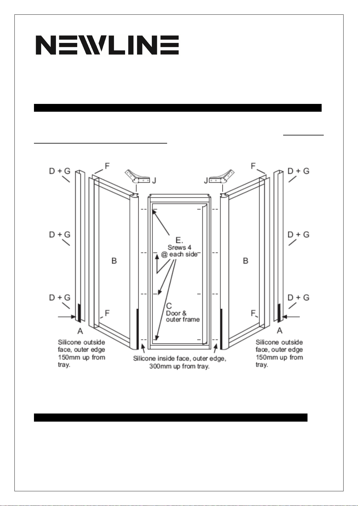
Diagram 1: View from outsi e oor shows pivot on left si e, to pivot on opposite si e turn panel ‘C’
over with the outer frame attache . Both si e panels are i entical an may be place on either si e
on the oorway.
PARTS LIST FOR 4MM & 6MM DOORS .
A
Wall profiles
x2
B Frame glass si e panel x2
C Glass oor an frame x1
H Screw capping x2
Accessory Pack for 6mm and 4mm door includes
:
D #8 x 25mm square rive screws x6
E&F #6 x 12mm square rive screws x12
G Rawl plugs x6

Page 3of 5
Accessory Pack
x1
6mm Frameless shower only:
Chrome covers x4
Clear washers
Han le x1
Frameless water seal x1
J
Top brace
x2
#6 x 12mm CSK screws (J) x8
#6 snap caps x5
4mm Frame shower only:
I Vinyl oor seal x1
INSTALLING THE FIXED PANEL ..
STEP 1Place wall profiles vertically on wall to
stra le the rain channel on NEWLINE trays only.
Silicone the rear face of the wall profile. Secure to
wall with #8 x 25mm square rive screws. Apply
silicone to the bottom 150mm, on outsi e face of
profile on outer e ge. Soli fixing is preferre .
Rawl plugs are supplie in case soli fixing cannot
be locate .
STEP 2Place fixe panel on tray an sli e over the
outsi e of wall profile. Push panel back firmly to
wall but o not secure. NOTE: The pre rille holes
in the fixe panel (refer Diagram 2 above) face the
insi e of the shower.
INSTALLING THE DOOR AND FRAME .
STEP 3It is necessary to remove the oor from its outer frame to complete the installation. Determine
which si e you woul like the oor to hinge from. Remember that the hinge blocks on the frame shoul
be on the ‘insi e’ of the oor an the oor operates by swinging outwar s into the bathroom. Cut the
tape hol ing the spacer at the top an bottom of the oor. Carefully remove the spacer. Remove the top
pivot mounting block from the outer frame an retain the top pivot block an screws. Separate the oor
an the frame by lifting the oor panel off the bottom pivot, or by carefully moving the frame over the
oor. Put the oor to one si e.
Place the outer frame on the shower tray between the fixe panels. Check again that:
a.)
The pivot block on the frame is on the insi e of the unit an
b.)
That it is on the correct si e of the opening.
Ensure that the panels an oor frame are in line at top an bottom. Silicone the vertical joint between

Page 4of 5
the outer oor frame an the corner post of the fixe panel to a istance of 300mm, refer D
iag
ram
1.
Silicone on the outer e ge only. Fix the frame to the corner posts by rilling into the corner post using
the pre rille holes in outer frame as a gui e. Use a 3mm rill bit an fit four 6 x 12mm square rive
screws to each si e of the frame. Locate the two rolle lengths of plastic screw capping an cut to length
to fit into the slot to cover the screw hea s (refer Diagram 3 above). When fitting, press gently into
position at several points along the length of the capping, to avoi stretching the material an work from
the top own. The two si e panels an outer oor frame are now resting on the tray but are not secure
to the wall profiles.
STEP 4 4mm framed door o ly Cut an arrowhea on the vinyl seal an insert it in the slot un er the
bottom e ge of the oor. Insert from the pivot block en with the curve face of the vinyl seal facing the
outsi e of the unit. Trim to full wi th of the oor with a sharp knife. Avoi excessive stretching of the
material as it will shrink back to length an may finish up being too short (Diagram 4). Insertion of the
seal is greatly assiste by spraying silicone into the slot un er the oor. Do not spray silicone onto the
vinyl as it will become ifficult to maintain a grip.
(6mm frameless door o ly) Fit the han les to the oor pane now. Cut the oor seal to butt joint against
the pivot block on both si es of the bottom pivot on the bottom e ge of the oor glass.
STEP 5 WARNING: Do not let the oor swing open without
being hel , as the fixe panels are not yet secure to the wall
profiles an the weight of the oor may cause the unit to fall
forwar .
To fit the oor first place a 3mm rill, four of the #6 x 12mm
square rive screws on the floor of the tray. Ensure that the
screw river is easily accessible an that you have the top pivot
block an its screws.
Stan ing outsi e the unit hol the oor in the open position
an locate the bottom pin into the bottom pivot block.
Maintain a firm grip on the oor panel at all times. Tilt the top
of the panel towar s the magnet si e of the oor to allow
sufficient clearance for the top pivot pin to swing inwar s
un er the top of the oor frame, place the top pivot block
onto the top pivot pin. Step into the
shower an close the oor into place on the magnet (Diag
ram
5). Maintain a grip on the oor panel an
the top of the frame. Relocate the top pivot block in position, making sure the oor closes on the magnet
an tighten the screws.
WARNING: Do not let the oor swing open without being hel , as the fixe panels are not yet secure
to the wall profiles an the weight of the oor may cause the unit to fall forwar .

Page 5of 5
STEP 6
Align the panels an oor parallel with the si es an
front of the tray. Check the magnet visually to ensure it is in
contact own the length of the oor an that the oor is
parallel with an has an even gap between the oor an
bottom rail. Secure the si e panels by rilling through the
panels onto the wall profiles. Use a 3mm rill bit. Fix with two
of the #6 x 12mm square rive screws to each si e at top an
bottom.
Check that the oor swings freely an a just on the pivot
block if require . Tighten all screws inclu ing those on the
oor glass clamps. Insert top braces (J) into the top of each
fixe panel corner post. The braces are not interchangeable
an fit each si e in epen ently. Secure in place by rilling
through the holes on the centreline of the extrusions an
fixing with 3 or 4 of the #6 x 12mm CSK
s
crews to each si e. Silicone aroun the external perimeter of the unit. Do not silicone insi e the unit
an o not silicone the fixe panels to the wall profiles other than as irecte in STEP 1. Allow 24hrs for
silicone to cure before using the unit (Diagram 6).
STEP 7 Shoul the magnet fail to hol oor close check both magnets are in contact 100% across the
wi th of both magnets, if not, a just oor glass on hinges. If this oes not solve the problem remove the
nylon retainer from the top of the magnetic strip on the oor only, remove the magnetic strip, turn 180°
(top to bottom) an refit.
STEP 8 6mm frameless door o ly Push fit the four chrome pivot block covers in position on the glass
clamps, to cover screw hea s. Cut an fit the splashguar to the bottom of the oor in two pieces, one
on each si e of an butting against the chrome pivot cover.
NB: If the glass clamp twists, a d the door drops, remove the door glass, take off the glass clamps,
thoroughly clea the i side faces of the glass clamp, a d the area o the glass where the clamp will be re-
located, with methylated spirits ( ot turpe ti e), repositio the clamp, a d refit the door glass.
CONTACT US .
NEWLINE HELPLINE
0508 NEWLINE (0508 639 5463)
Phone: 09 444 2053 Fax: 09 4430044
Email: info@ newline.co.nz www.newline.co.nz
This manual suits for next models
1
Table of contents
Other NewLine Other manuals

Popular Other manuals by other brands

Optex
Optex CX-502 installation instructions

Southwire
Southwire Shoreline Reels RL5 installation instructions

Lava
Lava Spark 285 user manual

Trail-Gear
Trail-Gear Rock Defense 303942-1-KIT Install instructions

First Alert
First Alert 2060DF Operations & installation guide

unidrain
unidrain MATLINE Construction guide


