Newlong DD-5 User manual

NEWLONG
MODEL
NEWLONG
MACHINE
WORKS,
LTD.
MATPARTS

(
Identifyingand
Ordering
Parts
)
[
+f
-
E
x
LZ
88
if
5
bj
Fu~
&
*
)
Where the constru~tion~permits,each part is stamped
with its
part
number.
On all
orders, please include part
number, part name
and
model name
of
machine.
(Safety
Rules
1
To prevent perdonal injury:
All power sources to the machine must be turned
off
before
threading, oiling, ajusting or replacing parrs.
Allcover and guards must
be
in position before operating
machine.
Do not
tamper
with
safety cover, guards,ctc.,while machine
is in operation.
Maintenance
(H
@
s
~~~R%~~EE&IJ\S&%F~~~~X%~~~~TL\~T~
Please keep in mind to handle the machine carefully
and
to msintenance the in good condition.
ZS;%
<
5
2
2
%
IZ%IZE{%IZI~!%\I~TT
2
Li0
Threadfuzz or dust must be cleaned with air or brush after
1
sa>{$%hf4$7~&
Lf:(;.
%'k~f;13i.9.
Hi;
the day's work.
~~~~~d7~~~~~~~~~~~~~o
MATPARTS

CONTENTS
3.
ADJUSTMENT
/
...............................................
4
3-1) ADJUSTING THREAD TENSION
-*-.--*
.***-.-
-uu"*
4
3-2)
SETTING NEEDLE AND ADJUSTING NEEDLE BAR HEIGHT
....--.-m.""
4
&tDiT!743I3ZBU$t&D&
2
3-3) TIMING SHUTTLE RACE BODY AND NEEDLE
*
***
**-**-u-""'
4
@*EA+St
82
Dl%
3-4) ADJUSTING PRESSER FOOT HEIGHT AND TIMING WITH NEEDLE
-**-".-
5
@~&a~st$t&aa%
3-5) ADJUSTING PRESSER FOOT PRESSURE
@I&EEcr)i@B
**
**
5
4.
REPLACING BOBBIN THREAD
/
@
. .
-
.
*
6
5.
OPERATION
/
................................................
-7
PARTS LIST
/
...............................
.............
9
MATPARTS

1.
SPECIFICATIONS
2.
THREADING
Maximum speed:
Stitch width:
Stitch
type:
Needle:
Thread:
2-1)
Needle
Thread
Pass needle thread
in
the order
1
to
1.0
below.
1,500
r.p.m.
,
---
Free feed
-
-
-
Lock stitch
216x
7
280,300
Cottonthread
(2016
or
2014
for
necdle;
2014
for
hohhin)
I
1
Thread stand pole
2
Needle thread eyelet
3
Thread tension, upper
Thread tension, lower
A+337T.
4
Tension spring
7.
5
Thread guide
Needle thread take-up
Thread guide
1%
(3'
>
?
.
7
Needle holder
4
.
8
Needle
'"
7;
&
(Bobbin
Thread)
.
Fig
1
1
MATPARTS

2-2)
Bobbin
Thread
2-21
-F
3+
Set the bobbin, full
with
thread.
in the shurtlc race body,and
F%(t,
@--@
~-~illWi~?$
t"i&fi;%CZ+z
.Y
b
L.
set the shuttle race
body
in
holder in the
order
@
to
(@
,;
g-
(=+.
,;
L
77;
g
,c
below.
Fig
2
3
-
MATPARTS

3.
ADJUSTMENT
3-1)
Adjusting
Thread Tension
3-1)
832lFU3aZ
e
~it$~i~+~14_%h~~~11~6031d.
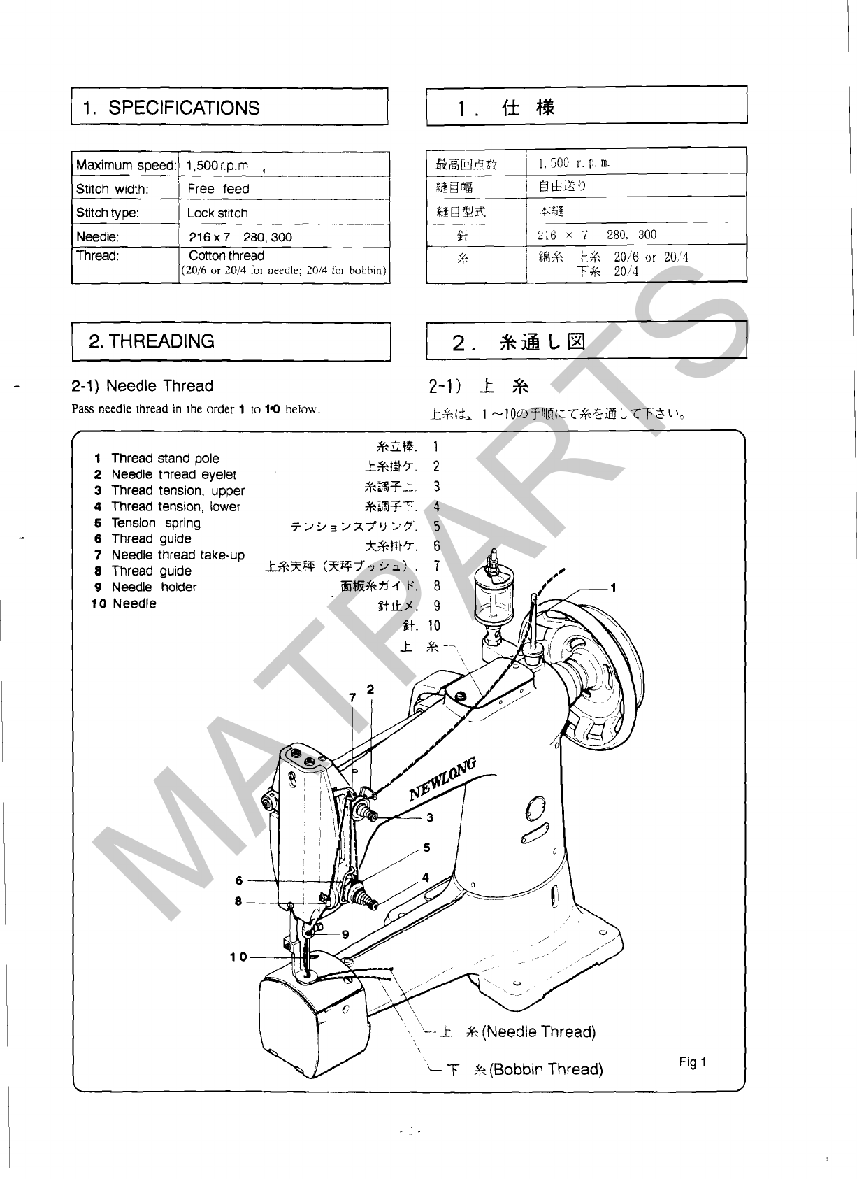
Fig 1
T%$(2)
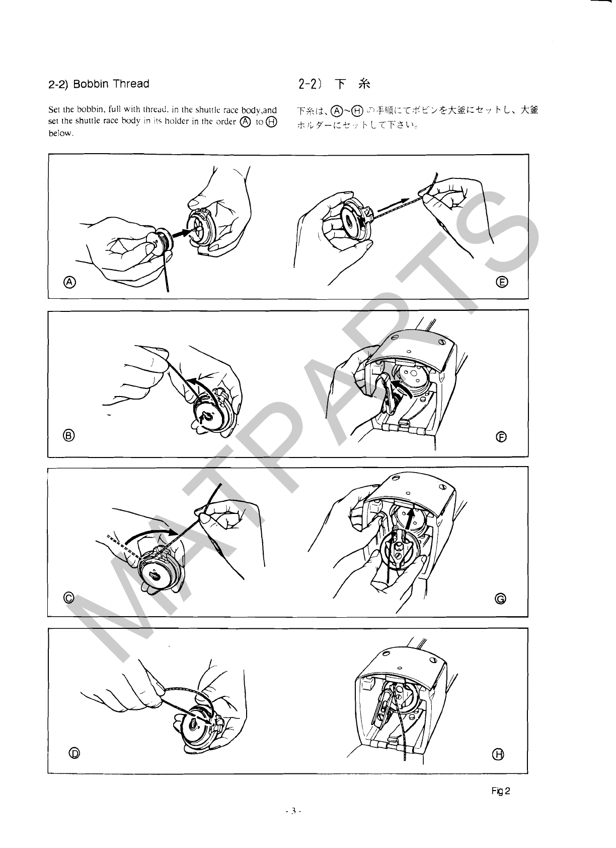
Check a sample seam to see the tightness
of
thread. For too
&flF~xy
1;
)
Y'J3555
<
L,
$i:k%h<T$$Tl\6
tight needle thread, loosen thread tension, upper
(I),
Figure
1
Tighten
it
if the needle thread is loose and raised too high. To
&gr$Eg<&
{
L?7;$
l
xll)
i
TBOE%l2kk&~~
-
-
adjust, turn thread tension nut.
t-.Y
i.fC-@L?ii~il)zE$,
3-2)
Setting
Needle
and
Adjusting Needle Bar Height
3-21
$tDRXktV3BCJ%t#~S2
(1) $+id
Fig
3?;T;$;g
4
Qtg(172132)
l~#&?+.
$thX~
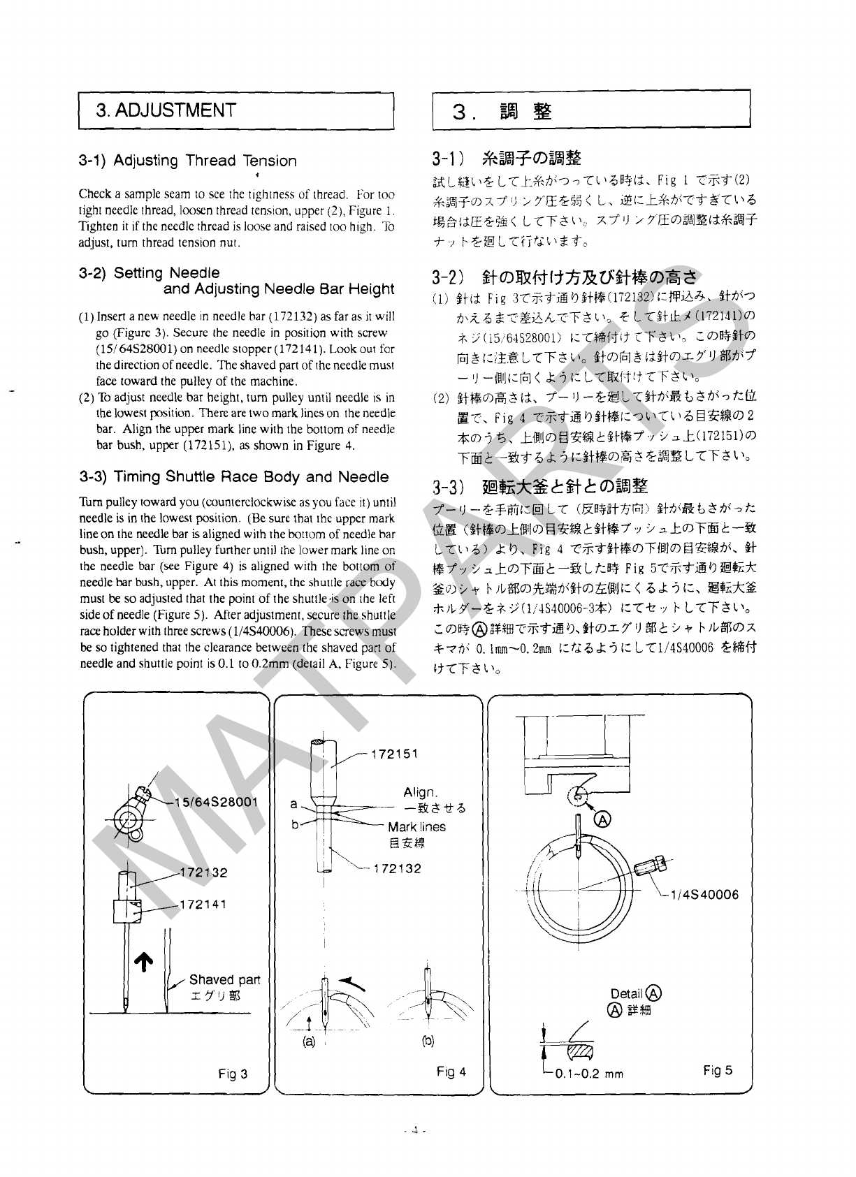
(1) Insert a new needle in needle bar (172132)asfar as
it
will
7S\L6
~~E;SA.TT'~
l)"
C
L7Stk.A
(172141)a
go (Figure
3).
Secure the needle in position with screw
(15164S28001)on needle stopper (172141).Look out tbr
the direction of needle. Theshaved part
of
the needle must
face toward the pulley of the machine.
-
(2)To adjust needle bar height, turn pulley until needle
1s
in
the lowest
position.
Thereare two mark lineson the needle
bar. Al~gnthe upper mark line with the bottom
of
needle
bar bush, upper (172151), as shown in Figure
4.
3-3)
Timing
Shuttle
Race
Body and
Needle
Turn pulley toward you (counterclockwise asyou face
it)
until
needle is in the lowest position.
(Be
sure that the upper mark
lineon the needle bar is aligned with the bottom of needle bar
bush, upper). Turn pulley further until the lower mark line on
the needle bar (see Figure
4)
is aligned with the bottom of
needle bar bush, upper: At this moment, the shut~lerace body
must
be
soadjusted that the point of the shuttleis
on
the left
sideof needle (Figure
5).
After adjustment, secure the shuttle
race holderwith three screws(114S40006). Thesescrews must
be
sotightened that the clearance between the shaved part of
needle and shuttle point
is
0.1 to0.2mm (detail
A,
Figure
5).
;i.
9
(i5:6+1~28001)
c:-crHc$if
rT'$
i
)7
L
o@Sta
m3i:iB3
L-crTS
L)o
$tom$
i2HDI-7'lJ
%7YY'
-
I)
-iRlli~6l<
k
3
4:
L7%!t4'!57T3
l)o
(2, $Jr~Dis,$
It,
7'-
'9
--%BL?$tA<i%t
3ni
-3
?:KL
a?.,
Fig
4
TZ$&t3$t@i:'l,l\?l~BRZ$$~2
*D5!5,
~~~~~~~%lc?$t~7~~>xk(l72151)D
TEk--%f
6
h
3
c:PtWIS3%3E
LTT:!
1~
3-3)
~&~S&$+kIn%@
7-
1)
-~+K~:IEI
LT
(EB+Zt36!)
gti~q~h
si~q-t:
G,23
($tt&OlkiFlilc?l€IZfSk$t%7'~.:,
.i
x_tOlf;%t:-%
L?l)b)
dr
13,
Fig
4
~,?;t$t@o>T;lflll~HEK:~hi,
@f
+$$Y
.i,_tDT&t:-!&LL:Q
Fig
57
iifiTiBfiC1Ek
Sol
.i
-P
+
1L%a%2%hX$ta&UltJi:
<
6
.k
3
i:,
?@%A%
;t;)LY-?&;i.
9
(li:+IS40006-3$)
t:T+
.r
i-
LTTf
1),
c
~B-+@;$~IT%-oB
5.
$tar
7
11
%f3
L
.i
+
111/%c~x
%77Y
0. lrrun-O.2mm
!:ti
b
5
C:
LT114S40006
%$%$f
if7-F$
l\o
MATPARTS

3-4)
Adjusting Presser Foot Height
andTiming with Needle
Adjust presser bar height sothat the clearance between throat
plate (174012)and presser foot (172301)is
4mm,
as shown
in Figure
6,
when presser foot is in the lowest position
.
lo
adjust, loosen screw (a)on presser bar spring adjust.
Timing of presser foot and needle is as follows. Adjust the
position of eccentric cam so that presser foot is in the lowest
position when needle
is
in the lowest position. The angle of
set
screw (c) is 45 degrees against upper shaft as shown in
Figure
6.
Secure the cam in position with set screw (c)after
the adjustment.
3-5)
Adjusting Presser
Foot
Pressure
Move presser bar holder so that presser bar spring is 45mm
long asshown in Figure
6.
Do not tighten screw
(b)
of presser
bar holder until the adjustment is complete.
/
\
Throat
plate
NC
Fig
6
\
1
MATPARTS

4.
REPLACING
BOBBIN
THREAD
Replace bobbin when bobbin thread
IS
used
up.
(1)
To
wind thread on a bobbin. ~nstalla bobbin on
pin
(a)
of
the thread winder (Figure 7),'tum lever
(b)
down, press
rota9 plate againsr V-belt and run the machine. It
is
a good
idea tow~ndthread
3
to4turnsonthe bobbin by hand before
installing the bobbin on the winder.
(2)
Thread winding diameter should be
2
rnln
smaller than
outer diameler of bobbin.
(3)
Thread winding diameter adjustment can be made
hy
loosening
screw
(C).
Turn screw clockwise to make thread
winding diameter large, counterclockwise make small.
(4)
lhreadw~ndingcan be stopped automatically by lever after
winding is finished.
(5)
Increase spring pressure of thread tenslon
(d)
in case of
onesided thread winding.
~*ki*~E'~!:~l\-c'i5
9
2+>
k
-17'.
T-?$h<ti
<
fX
?I
&
L~:GRLL~,;~E'~~:Z@L?F$L~,
(1)
Fig
7
?ri;f&4)
;f:
k'"iIi$g@<
@$li,
&&3D
(a)
~~:$'f')&$r[Q~ij,
(//:-(bj
LTVd
IL
blzWL-,Lj
I
9
~2;.d$.2L7T'k"~l:@$2$,
LC)%,
&G+.E'iiZ
3
.
4
~~TdL1-irh~i;.
$'f.
i%fi@3r:ER9v,3(f?7;$1\a
(2)
&B3
Zii$'k'>ulfi@k
9
znunt2!J\$
<
Bl\TTS
11,
(3)
%%43
@~3%$ii,
*
5
(C)
l:-cag
LTT2
L
1"
%
5?&&i:@f-t:&@$@l2f;;$
(
fi
9,
&df:llt:@
Tt:*B3@ii~J\$
<
fi9
2+c
(4)
%$81$,
@3$?9
2
Lt:
6.
@$hNi:
bjc-hi'kf
TRkL&%,
(5)-%~3
L-cL130$, *B$h<h\f:ek
6%3&Ii,
*a?
(dl
DX7')
;3"EEm?(
L77;l),
Fig
7
/
\
-
Thread guide
MATPARTS

5.
OPERATION
Be sure that the machine
IS
properly threaded according to
f
>
>56%;;36
k
3
&-$%?TJb:,
k*,
F*??&iB LB
threading and setting diagrams (Figure
1
and
2).
Turn pulley
(Fig
1,
Fig
2)
1:B-j'1\78:%3 L$.fo -?klh\G%T
toward you by hand for a full turn, and you will see bobbin
thread is pulled up above throat plate together with needle
~-~~-g+fi;it-~~-c
lm~z~aa,
ei$a&T*h'
thread. Separate needle and bobbin thread.
k*4zk
77Gl
7h\if Gt~T$t&kEizLkT&
g?fo
Now run the machine for normal operation.
€
LTk*2T*%QQbit2LTT$1\o
Tostop the machine and severthread,
be
sure that needle thread
qhh\
I;
t
9
>
gz$l-d&
L
77;s
1
,o
take-up
(7),
Figure
1,
is in the highest position, otherwise,
needle thread may come off needle hole.
&I:
t
9
25EkLT43%';TJ6#4Id, k%X@
(Fig
1-
7)h<@bkhi7
kfi8T*g@l77F$
L\o
ZD@8T*
MATPARTS

;&ssq3
=--
I-____
_--__
-----
ORDERING
PARTS
I
ORDERING PARTS
1.
Description of each part and
it5
stamp number
IS
described In th~sparts list.
Screws
and
nuts forparts are shown adjacent tothe relevant parts. When ordering pans, describe clearly Stamp
number with its name
of
part.
2.
The parts which have no Ref. Number can not be delivered independently; always order
it
as
an assembly.
3.
A
set of assembled parts is represented
hy
!he
stamp number of its main pans.
4.
The last figure on the parts stamp number advances on each improvement of the parts.
*
The parts list is subject to change without prior notice.
CONTENTS
;A
05
CONNECTING SHAFT, LOWER SHAFT
&
SHUTTLE PARTS
..............................
18
-v.%l,
7C@,
~~!%
MATPARTS

01
MAIN
FRAME,
BUSHING
&
OILING
PARTS
*$+
=
$819,
%IEhMR
MATPARTS

01
MAIN
FRAME,
BUSHING
&
OILING PARTS
*#
-
@3,
%;bR4%
Oiler
Tube Fitting(PC4-02)
Oil
Tube
Presser Liter Shaft Bushing, rear
Screw for 172381
Connecting Shaft
Screw for 172021
Arm
Shaft Bushing, rear
Oil
Felt
l
1
81185%
'
SZf%
l-E/%!
Ref.No.1 PartNo.
I
Description
1
Q'~Y
-
Screw for 171041
Ball
Cup
Cup Screw
Presser Bar
Bushing,
upper
Needle Bar Bushing, upper
Screw for 172151,172241
Oil
Tube
Presser Lifter Shaft Bushmg, front
76
Z
Remarks
1
Screw for 172391
I
Arm Shaft Bushing, front
Oil
Felt
Screw for 171051
Needle Bar and
Presser Bar Buhg,lower
Screw for 172171
,
Lower Shaft Bushing, front
1
Screw for 171071
I
Oil
Tube
Oil
Tube
1
Connecting Shaft Bushing, lower
1
Screw for 17203
1
I
,
Lower Shaft Buhg,rear
1
Screwfor 171061
MATPARTS

1
Special
Order
i
&)
I
MATPARTS

02
THREAD
TENSION
&
COVER
PARTS
*BF,
h/$-ME
Ref. NO.
--
1
%%"of?
Part No.
3%gf$
'ma
Description
1
Q'ty
Bevel Gear Cover, upper
+++~JJY'-
1
Screw
3
x
/
:..
11
Screw
2,
2
1
Thread Stand Base
Thread Stand Pole
%Il%
11
1
Top Cover
IZ
Spring Washer for 174061
1
XY'J
>9',7../
:/+-
1
Screw for 174061
2
-
:,,
/
1
Side Cover
91.
~.j3/i-
1
Screw for 174081
2,
.,
Face Cover
i68i
Screw for 174021
3
.
/
:"
Front Cover Thread Guide
EE&774
F'
1
;
Screw for 154192
2,
.y
Rotating Hook Cover Plate
j&;f;l/C-
I
Screw for 174043
3,
.,
j&j-J,<-&/<*
I;
Shuttle Race Cover Spring 1
Screw for 17405
1
3
.
:"
/
2
Nut for 174051
t.7
I-
2
Thread Tension Ass'y
mi
J@3$8
1
Tension Post
*3lFX@
1
Tension Disc
A
.
~RFjlllA
1
Tension Disc B
%W3DUB
1
Tension Releasing Disc
&#%%jlll
*$qFZYl)
97
11
Tension Spring 1
Tension Nut
*3Zj%t
*r
b
1
Tension Spring, Presser
J
>
9
1
Tension Spring, Inside
i+aFX?lJ
>9'm
1
Tension Spring, Outside
$qFXYIJ
>Y%
1
Thread Take-up Spring Regulator
&%?ke
1
Screw for 174261
i,
.>
1
Needle Clamp Thread Guide
;k5+#'r
Screw for 17423
1
3,
-2'
*BF$H
1
;
Thread Tension
Ass'y
Tension Post
%R3;t;f;&
I
1
Tension Disc
5w4FnIl
Tension Spring
*W?XY~J
29'
Tension Nut
*ZIT+
>Y
b
1
;
1
Thread Retainer Thread Eyelet
k&#'r
!
i
1
Screw for 174221
i
.
:'
1
1
Bevel Gear Cover, lower
T;++~J/\'-
+
.;;;
i
1
Screw '1
2,
.,
Screv:
1
Bobbin
Winder
~~~~
1
Screw
*q,
9
Washer
w3i2
fdl#Jfir
-
7'lL
1
i
Work Plate
(1)
Screw for 175241
2,
.,
Work Plate Bracket
?$jIi?~?-
7'1b2
Screw for 175252
-$,
-2
ti4
%?
Remarks
(2.
3)
*
Special
Order
(
%
&)
-
13
-
MATPARTS

03
ARM SHAFT
&
NEEDLE
BAR PARTS
k@\
~t@MR
Ak
MATPARTS

03
ARM SHAFT
&
NEEDLE
BAR PARTS
+@,
~t%MR
%$€I
Description
Pulley
Screw for 171081
Screw for 171081
Screw
Bevel Gear, upper
Screw for 171091
Arm Shaft
Needle Bar Crank
Screw
Screw
Cotter Pin
Screw for 17208
1
Needle Bar Connecting
Link
Thread Take-up Crank
Needle Thread Takeup
Ass'y
Eyelet
Screw for 172201
Stopper
Pin
Screw
Needle Thread Takeup Pin
Screw
Screw for 172221
Needle Bar Connecting Stud
Screw for I72111
Needle Bar
Needle Clamp Stud
Screw for 172141
Needlei216x7-280)
Needle(216X7-300)
Needle Bar for Needle DDX 1
Needle(DDX 1
3%)
Slide Block
MATPARTS

04
PRESSER
FOOT
&
LIFTER
PARTS
@I&,
#qx%YMR
MATPARTS

04
PRESSER FOOT
&
LIFTER PARTS
jFx&,
tT=EYM%
%E%f&
Description
%
E
Remarks
!
Connecting
Rod
,
Screw
I
Oil
felt
'
~phtPin
I
Lifting Presser Bar Eccentric
1
Screw for 172311
/
Pm
'
Lower shaft Crank
Pin
I
Screw for 172351
'
Rod
Lower Shaft Crank
1
Screw for 172341
I
(
Fulcrum
Screw for 172361
1
Presser Lifter
Shaft
Presser Bar Spring Adjuster
1
Screw for 172251
I
Washer
Presser Lifter Lever
Taper Pin
1
Ferrule
Presser Bar Spring
Presser
Bar
Presser Bar Lifting Bracket
Screw for 172281
Presser Foot
Screw for 172301
Nut for 172301
MATPARTS

05
CONNECTING
SHAFT,
LOWER
SHAFT
&
SHUTTLE
PARTS
3$tB\
-F%,
%Mi%
MATPARTS

05
CONNECTING
SHAFT, LOWER SHAFT
&
SHUTTLE PARTS
ah\
-F@\
3$MR
I
I
%El++
Ref. No. Part NO.
%,",Z
Description
Bevel Gear Pinion
Screw for
171101
Connecting Shaft
Bevel Gear, lower
Screw for
172041
Lower Shaft
Lower Shaft Collar
Screw for
172061
Shuttle
Race
Cylinder
Screw for
173011
Shuttle Race
Screw for
GO2004
Bobbin
Shuttle Hook Ass'y
Shuttle Body
Ring
Bobbin Case Ring Spring
Screw for
GO2006
Bobbin Case Tension Spring
Screw for
GO2005
Screw for
C0200.5
Pin
Plate Spring
Screw for
173121A
Shuttle Hook Bracket
Spring
Screw for
173111
Shaft
Screw for
173091
Screw for
173081
Throat Plate Fitting
Screw for
173071
Screw for
173071
Screw
for
174011
I
%
E
~
Remarks
MATPARTS
Other manuals for DD-5
1
Table of contents
Other Newlong Sewing Machine manuals