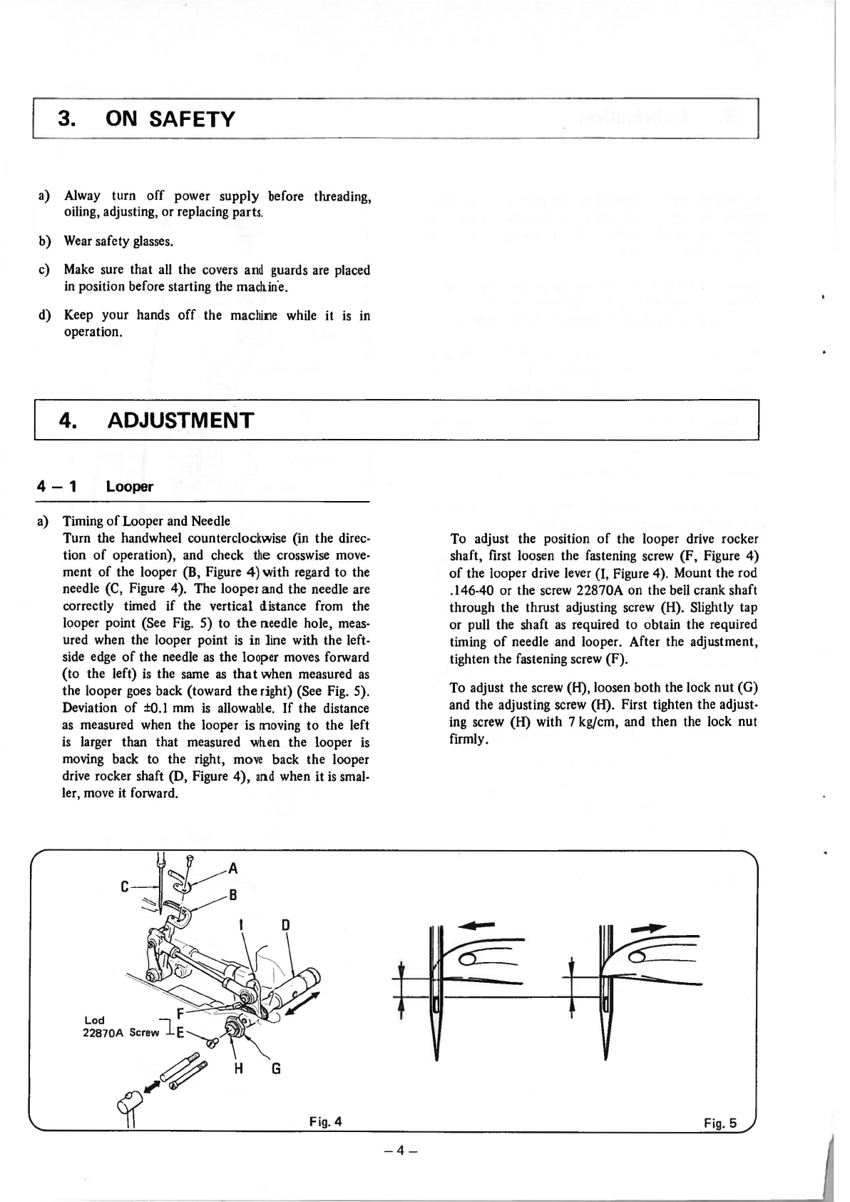
4-4
Change
of
Stitch Length (Figure 13 refers)
Your machine is adjusted to the stitch length
of
7
mm
in
our plant before shipment. You can change the stitch
length
in
the following procedure when necessary:
Loosen the nut (B)
of
the feed regulating stud, and turn
the screw (D) on the dial. Turning
it
to the right will
make the stitch smaller (S), and turning it to the left
larger (L). Tighten the nut (B) only by half and turn
the pulley by hand to produce a length
of
seam to con-
firm whether the desired stitch length is obtained or not.
After the adjustment, tighten the nut (B) firmly.
Note: Nut (B) has left-hand threads.
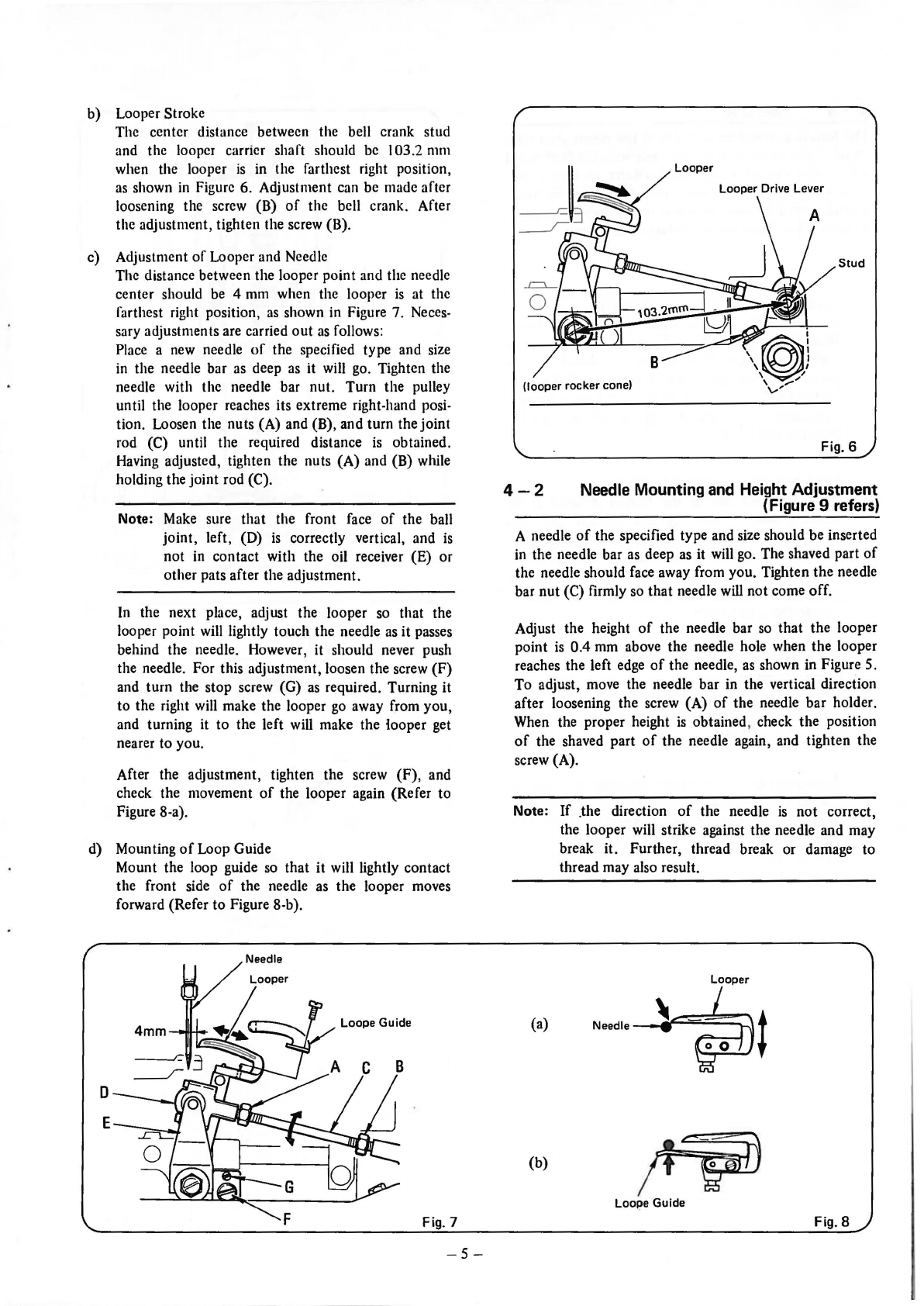
4-5
Needle Guard (Figure 14 refers)
the upper edge
of
the needdle hole must be even with
the lower surface
of
the needle guard
{B)
when the
needle (A)
is
in
the lowest position
in
.its travel. To adjust,
loosen the screw (C) and move the needle guard (B)
in
the vertical direction.
Make
necessary adjustment
so
that the clearance between the needle (A) and the
needle guard (B)
is
0 to 0.1 mm,
as
shown in Figure 14.
Be
careful that the needle (A) will not contact the needle
guard (B).
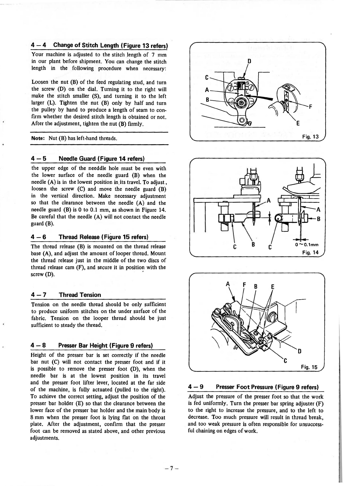
4-6
Thread
Release
(Figure
15
refers)
The thread release (B)
is
mounted on the thread release
base (A), and adjust the amount
of
looper thread. Mount
the thread release just in the middle
of
the two discs
of
thread release cam (F), and secure it in position with the
screw (D). ·
4-7
Thread Tension
Tension on the needle thread should be only sufficient
to produce uniform stitches on the under surface
of
the
fabric. Tension on the looper thread should be just
sufficient to steady the thread.
4-8
Presser
Bar Height (Figure 9 refers}
Height
of
the presser bar
is
set correctly
if
the needle
bar nut (C) will not contact the presser foot and
if
it
is
possible
to
remove the presser foot (D), when the
needle bar is at the lowest position in its travel
and the presser foot lifter lever, located at the far side
of
the machine,
is
fully actuated (pulled to the right).
To achieve the correct setting, adjust the position
of
the
presser bar holder {E) so that the clearance between the
lower face
of
the presser bar holder and the main body
is
8 mm when the presser foot
is
lying flat on the throat
plate. After the adjustment, confirm
that
the presser
foot can be removed
as
stated above., and other previous
adjustments.
- 7 -
D
F
Fig.
13
Fig.
14
A F
D
Fig.
15
4-9
Presser
Foot
Pressure
(Figure 9 refers)
Adjust the pressure
of
the presser foot
so
that the work
is
fed uniformly. Turn the presser bar spring adjuster
(F)
to the right to increase the pressure, and to the left to
decrease. Too much pressure will result in thread break,
and too weak pressure
is
often responsible for unsuccess-
ful chaining on edges
of
work.
From the library of: Superior Sewing Machine & Supply LLC