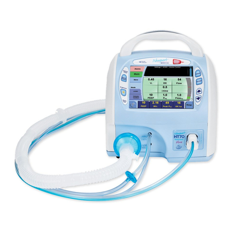
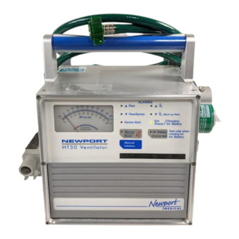
Newport Medical Instruments HT70 User manual

Newport Medical Instruments, Inc.
Newport HT70 Ventilator
Operating Manual
for Plus Model
OPRHT70-2 Rev. F
06/13
0344
Newport Medical Instruments, Inc.
1620 Sunower Ave.
Costa Mesa, CA 92626
Tel: 1.714.427.5811
Tel: 1.800.451.3111 (USA Only)
Fax: 1.714.427.0489
Customer Service ext. 282
www.ventilators.com
email: Info@ventilators.com


HT70 Operating Manual OPRHT70-2
Revisions Date Description
Rev A October 2011 New release
Rev B November 2011 Miscellaneous type corrections,
text change on page 3-3, 7-1, 7-3
regarding Power Pac.
Rev C May 2012 Add Operating Manual Reivison.
Notice regarding the following
change: Pulse Oximeter accessory
and related functions no longer
available.
Rev D July 2012 Software update ver. P05.12.10
and above, Remove references
to optional Pulse Oximeter (not
available), Change Slope/Rise
setting was: 1 is fastest, is: 1 is
slowest.
Rev E November 2012 Update to correct image reversal
in F-1 and F-2, callout labels on
various drawings converted to
numbers and referenced in text or
added to table. Remove reference
to Aequitron nurse call systems.
Replace warranty details with who
to contact information.
Rev F June 2013 Add information about the
Aequitron Remote Alarm System.
OPR360U A0509
5-1
5
OPR360U A0509
5-1
5
OPRHT70-2 F0613
Manual Revision History


Thank you for using the Newport HT70 family of ventilators. With
the HT70 you not only get a great ventilator, you get the support
of Newport Medical. Since 1981 we have maintained a focused
commitment to the design, production and sale of ventilators. We
have dedicated our efforts to providing ventilators that are easy to
use, clinically versatile, and cost effective.
We know that ventilatory support is critical in emergency and critical
care situations. But for many of our customers, it is also a part of
their daily lifestyle. The HT70 Ventilators offer home care users the
expanded mobility that allows them to experience more freedom in
their lives than many have ever known before.
We have designed this manual to be comprehensive and still very
user friendly. For the best performance from your HT70 Ventilator,
please take the time to review this manual completely.
See our contact information on the following page for complete
details.
OPR360U A0509
5-1
5
OPR360U A0509
5-1
5
OPRHT70-2 F0613
Contact Information


OPR360U A0509
5-1
5
OPR360U A0509
5-1
5
OPRHT70-2 F0613
Contact Information
Contact Information
Telephone:
+1.714.427.5811
1.800.451.3111 (US only)
Fax:
+1.714.427.0489
Departments:
Customer Service (Ext. 282)
Technical Services (Ext. 500) available 24/7
Clinical Support (Ext. 123) available 24/7
Operational Hours:
Days: Monday through Friday
Hours: 8:00 am to 5:00 pm (PST)
Emergency After-hours: 24-Hour Clinical and Technical Support
Email:
Customer Service: customers@ventilators.com
Clinical Education and Support: clinical@ventilators.com
Technical Education and Support: techservice@ventilators.com
Internet:
www.ventilators.com
Shipping Address:
Newport Medical Instruments
Attn: Receiving Department
1620 Sunower Avenue
Costa Mesa, CA 92626, USA
EC REP
Authorized European Representative
Emergo Europe
Molenstraat 15
2513 BH, The Hague
The Netherlands


Unfold to view drawing on reverse side
OPRHT70-2 F0613
FOLDOUT DRAWINGS
Use the following drawings as reference while reviewing
the manual sections

Figure F-1 English Version- Front Panel Overview
OPRHT70-2 F0613
F-1
1. Breath Delivery Indicator LED. Flashes green with every breath delivered by the
ventilator.
2. External Power LED. Lights green whenever external power is connected. This
also indicates that the Internal Dual Battery System is being charged.
3. Manual Inflation button. Press and hold this button to deliver ow to the patient.
The ventilator will deliver ow at the current settings while the button is pressed.
Flow delivery is limited to a maximum of 3 seconds or until the High Pressure
alarm setting is reached.
4. Brightness button. Press this button repeatedly to scroll to one of four screen
brightness levels.
5. Device Alert LED. Lights red when there is a device alarm. Take the ventilator out
of service and use an alternate means of ventilation until resolved.
6. Patient Gas Output. Attach patient breathing circuit tubing here.
7. Proximal Pressure Line connector. Attach proximal pressure tubing here.
8. Exhalation Valve Drive Tubing connector. Attach exhalation valve drive tubing here.
9. Alarm Violation LEDs. LEDs in the handle light to indicate alarm conditions.
10. Alarm Silence/Reset button. Press this button to silence the audible alarm for 1
minute. Once an alarm condition has been corrected, press this button to clear/
reset the alarm message and latched indicators.
11. Alarm Silence LED. Remains lit during the one minute alarm silence period.
12. Cancel button. Press this button if you want to cancel changes that have not
already been accepted.
13. Accept button. Press this button to accept/conrm all changes made to control
settings.
14. s Up / tDown Arrow buttons. Press to change a highlighted parameter up/down
by one unit. Hold down continuously and the parameter will change at an increasingly
quicker pace.
15. Touch Screen User Interface. Touch screen to access alarms and parameter settings.
16. Flow Sensor connector. Attach on-airway ow sensor here.
9
10
11
12
13
14
15
1
2
3
4
5
6
7
8
16

Unfold to view drawing on reverse side
OPRHT70-2 F0613

Figure F-2 Symbols Version- Front Panel Overview
OPRHT70-2 F0613
F-2
1. Breath Delivery Indicator LED. Flashes green with every breath delivered by the
ventilator.
2. External Power LED. Lights green whenever external power is connected. This
also indicates that the Internal Dual Battery System is being charged.
3. Manual Inflation button. Press and hold this button to deliver ow to the patient.
The ventilator will deliver ow at the current settings while the button is pressed.
Flow delivery is limited to a maximum of 3 seconds or until the High Pressure
alarm setting is reached.
4. Brightness button. Press this button repeatedly to scroll to one of four screen
brightness levels.
5. Device Alert LED. Lights red when there is a device alarm. Take the ventilator out
of service and use an alternate means of ventilation until resolved.
6. Patient Gas Output. Attach patient breathing circuit tubing here.
7. Proximal Pressure Line connector. Attach proximal pressure tubing here.
8. Exhalation Valve Drive Tubing connector. Attach exhalation valve drive tubing here.
9. Alarm Violation LEDs. LEDs in the handle light to indicate alarm conditions.
10. Alarm Silence/Reset button. Press this button to silence the audible alarm for 1
minute. Once an alarm condition has been corrected, press this button to clear/
reset the alarm message and latched indicators.
11. Alarm Silence LED. Remains lit during the one minute alarm silence period.
12. Cancel button. Press this button if you want to cancel changes that have not
already been accepted.
13. Accept button. Press this button to accept/conrm all changes made to control
settings.
14. sUp / tDown Arrow buttons. Press to change a highlighted parameter up/down
by one unit. Hold down continuously and the parameter will change at an increasingly
quicker pace.
15. Touch Screen User Interface. Touch screen to access alarms and parameter settings.
16. Flow Sensor connector. Attach on-airway ow sensor here.
9
10
11
15
16
1
2
3
4
5
6
7
8
12
13
14

Unfold to view drawing on reverse side
OPRHT70-2 F0613

OPRHT70-2 F0613
F-3
1. Screen Selections buttons. Touching any one of these buttons will take you to the new
screen. The More screen includes links to Event, Trends, Wave and Utility screens.
2. Mode selector. Touching this button scrolls through the mode choices. The mode will
not change until you press the Accept button.
3. Breath Type selector. Touching this button toggles the breath type choice. The breath
type will not change until you press the Accept button.
4. Help button. Touching this button enables a tutorial for each feature on the screen.
Touch the help button then touch any button for an explanation of that feature.
5. Monitored Data buttons. Touching any one of these four buttons opens a screen with a
view of monitored parameter choices to display in that button.
6. Message display. This area shows all informational and alarm messages and current
NIV selection, mode, and breath type selection. During an alarm violation this area will
light red for High Priority, amber for Medium Priority and yellow for Low Priority alarms
and display the alarm message.
7. Battery Charge Level indicator. Shows the charge level of the “Power Pac” battery
pack (blue icon) during external power or Power Pac use or the charge level of the
Backup Battery (red icon) during Backup Battery use.
8. Pressure Bar. Indicates dynamic pressure in the patient circuit in green, the High and
Low Pressure Alarm settings in red and the peak pressure of the last breath in green.
9. Parameter Setting buttons. Touching any one of these buttons will activate the
parameter to allow adjustments.
10. Patient Effort indicator. Flashes green to show a spontaneous patient effort.
11. Domain button. The HT70 can be set up in one of three Domains: Basic, Transport and
Hospital. Touch to scroll through the Domain choices. Press Accept to conrm choice.
12. AutoLock/Unlock button. This button is only visible if Auto Lock is enabled and the
panel is locked. Touch and hold for 3 seconds to unlock touch screen buttons.
NOTE: While operating on battery power with Power Save enabled and all alarms cleared, the
touch screen will go to sleep after 2 minutes. Just touch the screen to bring it back into view.
17
6
8
9
10
11/12
2
3
4
5
Figure F-3 HT70 Plus Model Touch Screen (Hospital Domain)

OPR360U A0509
5-1
5
OPR360U A0509
5-1
5
Table of Contents
OPRHT70-2 F0613
1 Introduction
Brief Device Description............................................................. 1-1
Intended Use .............................................................................. 1-3
Warnings, Cautions and Notes................................................... 1-3
2 Overview of Controls, Screens and Connectors
Front Panel Overview ................................................................. 2-1
Touch Screens Overview............................................................ 2-1
Internal Dual Battery System Overview...................................... 2-1
Rear Panel Overview .................................................................. 2-2
Right Side Overview ................................................................... 2-3
Left Side Overview ..................................................................... 2-3
Bottom Panel Labeling ............................................................... 2-4
3 Set up and Pre-use Preparations
Unpack the HT70 Ventilator........................................................ 3-1
Assemble the Ventilator.............................................................. 3-2
Connect to AC Power................................................................. 3-2
Using the Power Switch .............................................................3-3
Make Parameter Changes..........................................................3-4
Attach a Patient Circuit...............................................................3-4
For use with a third party humidier.....................................3-5
For use with an HME ............................................................3-8
Using the On-airway Flow Sensor...................................... 3-10
Connect Optional Accessories..................................................3-11
Air/Oxygen Entrainment Mixer.............................................3 -11
Low Flow Oxygen Reservoir............................................... 3-12
D.C. Auto Lighter Power Adapter ....................................... 3-14
Aequitron Remote Alarm Cable Accessory........................ 3-14
4 Navigating the HT70 Screens
Touchscreen (Graphical User Interface) Layout ......................... 4-1
Primary Screen Buttons and Displays........................................ 4-1
Ventilator Settings Adjustment ...................................................4-4
Start Up Screen Navigation (Standby Condition Only) ..............4-4
Circuit Check Button ............................................................4-5
How to Perform a Circuit Check.....................................4-5
If the Circuit Check Fails.................................................4-6
Activate Preset Button.......................................................... 4-7
How to Use a Preset....................................................... 4-7
Start Ventilation Button .............................................................. 4-7

OPR360U A0509
5-1
5
OPR360U A0509
5-1
5
OPR360U A0509
5-1
5
OPR360U A0509
5-1
5
OPRHT70-2 F0613
Table of Contents
Alarms Screen Navigation ..........................................................4-8
Main Screen Navigation .............................................................4-9
More Screen Navigation............................................................4 -11
More Screen Details ........................................................... 4-13
Events ........................................................................... 4-13
Trends ........................................................................... 4-14
Waves ........................................................................... 4-15
O2 Cylinder Data Screen.............................................. 4-16
Calibrate O2 Monitor .....................................................4-17
Utility Screen ............................................................................ 4-18
Utility Screen Details .......................................................... 4-19
Time/Altitude Screen .................................................... 4-19
Customize Settings Screen .......................................... 4-20
Custom Presets ............................................................ 4-21
Back Up Ventilation ...................................................... 4-22
Domain Navigation ................................................................... 4-23
Hospital .............................................................................. 4-23
Transport ............................................................................ 4-24
Basic ................................................................................ 4-25
5 Operating the HT70 Ventilator
Quick Check Procedure ............................................................. 5-1
Introduction .......................................................................... 5-1
Equipment Needed............................................................... 5-1
Pretest Inspection................................................................. 5-1
Set Up .................................................................................. 5-1
Standard Test Settings ......................................................... 5-2
Quick Check Procedure ....................................................... 5-2
Pass / Fail Check Off Sheet .................................................5-4
Patient Setup Procedure ............................................................5-5
Troubleshooting Guide ............................................................... 5-7
6 Ventilator Alarms
Setting Alarms ............................................................................ 6-1
Alarm Quickset ..................................................................... 6-1
Alarm Indicators ......................................................................... 6-2
Alarm Silence/Reset Button ................................................. 6-2
Alarm Silence LED................................................................ 6-2
User Adjustable Alarms.............................................................. 6-2
Backup Ventilation......................................................................6-6
Automatic Alarms .......................................................................6-6
Battery Alarms............................................................................6-9

OPR360U A0509
5-1
5
OPR360U A0509
5-1
5
OPR360U A0509
5-1
5
OPRHT70-2 F0613
Table of Contents
7 Battery Operation
Internal Dual Battery System.......................................................7-1
Power Pac Battery Pack..............................................................7-1
Backup Battery........................................................................... 7-2
Conditions that Affect Battery Use Time.................................... 7-2
Check the Battery Charge Level and Battery Time Estimator ... 7-3
Best Use Tips ............................................................................. 7-3
Battery System Maintenance ..................................................... 7-4
Power Pac Battery Pack Removal.............................................. 7-4
Battery Alarms Overview............................................................ 7-5
Power Accessories..................................................................... 7-6
8 Cleaning and Maintenance
Cleaning and Disinfecting........................................................... 8-1
Ventilator .................................................................................. 8-1
Accessories ................................................................................ 8-2
Low Flow Oxygen Reservoir................................................. 8-2
Air/Oxygen Entrainment Mixer.............................................. 8-2
Reusable Breathing Circuits.......................................................8-3
Air Intake Filter............................................................................8-3
Proximal Inline Filter ...................................................................8-4
Maintenance Guidelines .............................................................8-4
Routine Maintenance............................................................8-4
6 Month Maintenance...........................................................8-5
12 Month Maintenance.........................................................8-5
24 Month Maintenance.........................................................8-5
15,000 Hour Maintenance ....................................................8-6
General Warnings .......................................................................8-6
Factory Maintenance or Repair .................................................. 8-7
Repacking/Return Information ................................................... 8-7
9 Specifications
Front Panel Buttons - Symbols Version ..................................... 9-1
Miscellaneous Reference Symbols ............................................ 9-2
Controls / Monitors.....................................................................9-3
Monitor Data Selections.............................................................9-4
Front Panel Membrane Buttons and Indicators .........................9-4
Alarms ..................................................................................9-5
User Adjustable ....................................................................9-5
Automatic .............................................................................9-5
Hardware Requirements............................................................. 9-7
Environment................................................................................9-8
Size and Weight..........................................................................9-8

OPR360U A0509
5-1
5
OPR360U A0509
5-1
5
OPR360U A0509
5-1
5
OPRHT70-2 F0613
Table of Contents
Factory Default Parameters........................................................9-9
Miscellaneous ............................................................................9-9
(optional) Air / Oxygen Entrainment Mixer..................................9-9
(optional) Low Flow Oxygen Reservoir.......................................9-9
Regulatory and Agency Standards .......................................... 9-10
10 Explanations of Modes and Controls
Explanation of Modes and Controls......................................... 10-1
Foldout Diagrams
English Version - Front Panel Overview ..................................... F-1
Symbols Version - Front Panel Overview ................................... F-2
HT70 Plus Model Touch Screen.................................................F-3

Introduction
Section 1:
Introduction

OPR360U A0509
5-1
5
This manual suits for next models
5
Table of contents
Other Newport Medical Instruments Fan manuals
Popular Fan manuals by other brands

BlowHard
BlowHard BH-20 Operation manual
Black & Decker
Black & Decker Typhoon BDTF1010 Series Use and care book

Hunter
Hunter 21711 Manual de Installatión y Operatión
Clatronic
Clatronic T-VL 2976 instruction manual
Ellington
Ellington FAR14ABZ3W installation guide

QUORUM INTERNATIONAL
QUORUM INTERNATIONAL The Jellyfish installation instructions
