Newport Vessels Pontoon Series User manual

Electric Trolling Motor
Pontoon Series
User’s Manual
Please read and retain this manual before using product
REACH RoHS

2
Contents
1 General Information. . . . . . . . . . . . . . . . . . . . . . . . . . . . . . . . . . . . . . . . 4
2 Specications .............................................. 4
3 WiringandBatteryRecommendations ................... 5
3.1 Battery Type............................................5
3.2 Circuit Protection.......................................5
3.3 Cable Size..............................................5
4 Safety Information ......................................... 6
5 FirstTimeRunning ......................................... 7
6 MountingBracketInstallation ............................ 8
7 Motor Operation........................................... 12
7.1 Battery Connection Method (12 Volt only) ............. 12
7.1.1 Connection With One Battery (12V DC) .............. 12
7.1.2 Connection With Two Batteries in Parallel (12V DC) ... 12
7.2 Battery Connection Method (24 Volt only) .............. 13
7.2.1 Connection With Two Batteries in Series (24V DC) .... 13
7.3 How To Control The Motor ............................. 13
7.3.1 On/Off Speed Control ............................. 13
7.3.2 Adjust Handle Position ............................ 14
7.3.3 Battery Level Indicator ............................ 14

3
7.3.4 Adjusting Motor Depth ............................ 14
7.3.5 Adjusting Steering Tension ........................ 14
8 How to Replace the Propeller ............................ 15
9 Daily Maintenance ........................................ 16
10TroubleShooting .......................................... 17
10.1 Loss of Power ......................................... 17
10.2 Motor Makes Excessive Noise or Vibration............. 17
10.3 Motor Fails to Run..................................... 17
10.4 Motor Loses One or More Speeds...................... 18
11AboutCircuitbreaker ..................................... 18
11.1 Function of the circuit breaker......................... 19
12DeclarationofConformityforRecreationalCraft ...... 20
13CustomerSupport........................................ 20

4
1 General Information
Thank you for purchasing our product. We hope that you enjoy it!
Newport Vessels trolling motors are designed and developed by profes-
sional engineers and the design is continually honed and improved.
There are a wide range of Newport Vessels outboard motors, from
36lbs to 86lbs,to suit every customer’s requirements and uses.
Please read and retain this manual before using this electric motor.
This manual contains information that describes the procedure for
safe operation and daily maintenance of your electric motor. Safe
operation will prevent personal injury and damage to the product.
2 Specifications
ItemNo. Thrust
in LBS
Thrustin
KG Input Input
Power
Pontoon-55 55 25.0 12V, 52A 624W
Pontoon-86 86 37.2 24V, 48A 1152W
Since speed depends on many factors, such as loading, water condi-
tion, hull type, wind speed, etc., it is difficult to give accurate speed
ratings. Instead refer to the thrust and power ratings provided above.

5
3 Wiring and Battery Recommendations
3.1 Battery Type
Recommended battery(s): 12-volt Deep Cycle battery or Marine battery.
To extend running time,either a larger capacity or an additional
battery can be used. See section on battery connection method.
NOTE: 86lbs model requires a 24-volt battery.
3.2 Circuit Protection
It is recommended to install a manual reset circuit breaker in the
electric outboard motor leads within 72 Inches (1.8m) of the battery(s).
3.3 Cable Size
If extending the standard battery cable supplied with the product,
Newport Vessels recommends the use of 8-gauge wire (13mm2 wire).
Be sure all switches are in the OFF position
before connecting to battery or batteries. Electrical arcing near
the battery could cause an explosion. The battery produces
hydrogen and oxygen gases while charging. This potentially
explosive mixture escapes through the fill vent cell caps and may
form an explosive atmosphere around the battery for several hours
after it has been charged. Electrical arcing or flames can ignite the
gas and cause an explosion, which may shatter the battery and could
cause blindness or other serious injury.
Batteries contain sulfuric acid, which can cause
severe burns. Avoid contact with skin, eyes and clothing.

6
4 Safety Information
•Do not allow children to operate the electric outboard motor.
•Do not modify the unit in any way or add accessories not intended
for this product.
•Never fully submerse the unit.If unit is accidentally submersed,
disconnect battery and leave to dry.
•To prevent accidental damage to the fiberglass shaft, do not over
tighten the mounting bracket.
•Only use this product between the temperatures -4Fº to +113Fº
(-20ºC to +45ºC).
•User(s) should always wear approved life jackets.
Always disconnect power from the motor when
replacing propeller, removing debris around the prop, charging
batteries, transporting boat,or when the motor is not in use.

7
5 First Time Running
1. Place Electric Outboard onto the back of the vessel in the Stow
away position.
2. Loosely tighten the Transom Mounting Screws until they grip the
Transom Mount.
3. Press the Tilt Lever and slowly let the motor enter the water.
4. Use the Depth Adjuster Collar to adjust the height of motor. Recom-
mended running depth is between 6in to 12in (15cm to 30cm)
below the waterline.
5. When you are satisfied that the motor is at a safe depth, and
isn’t too close,or in danger of hitting the bottom of the water way,
you may proceed to tighten the Transom Mounting Screws.
6. Once this is done it should be safe to connect the battery to the
motor. Ensure that the twist grip is in the neutral position and that
the nuts are tight on the terminals to prevent a poor connection.
7. Select the desired speed and direction using the twist grip on the
tiller arm.
8. Do not go from full forward speed to full reverse speed without let-
ting the propeller stop turning first or motor damage may occur.

8
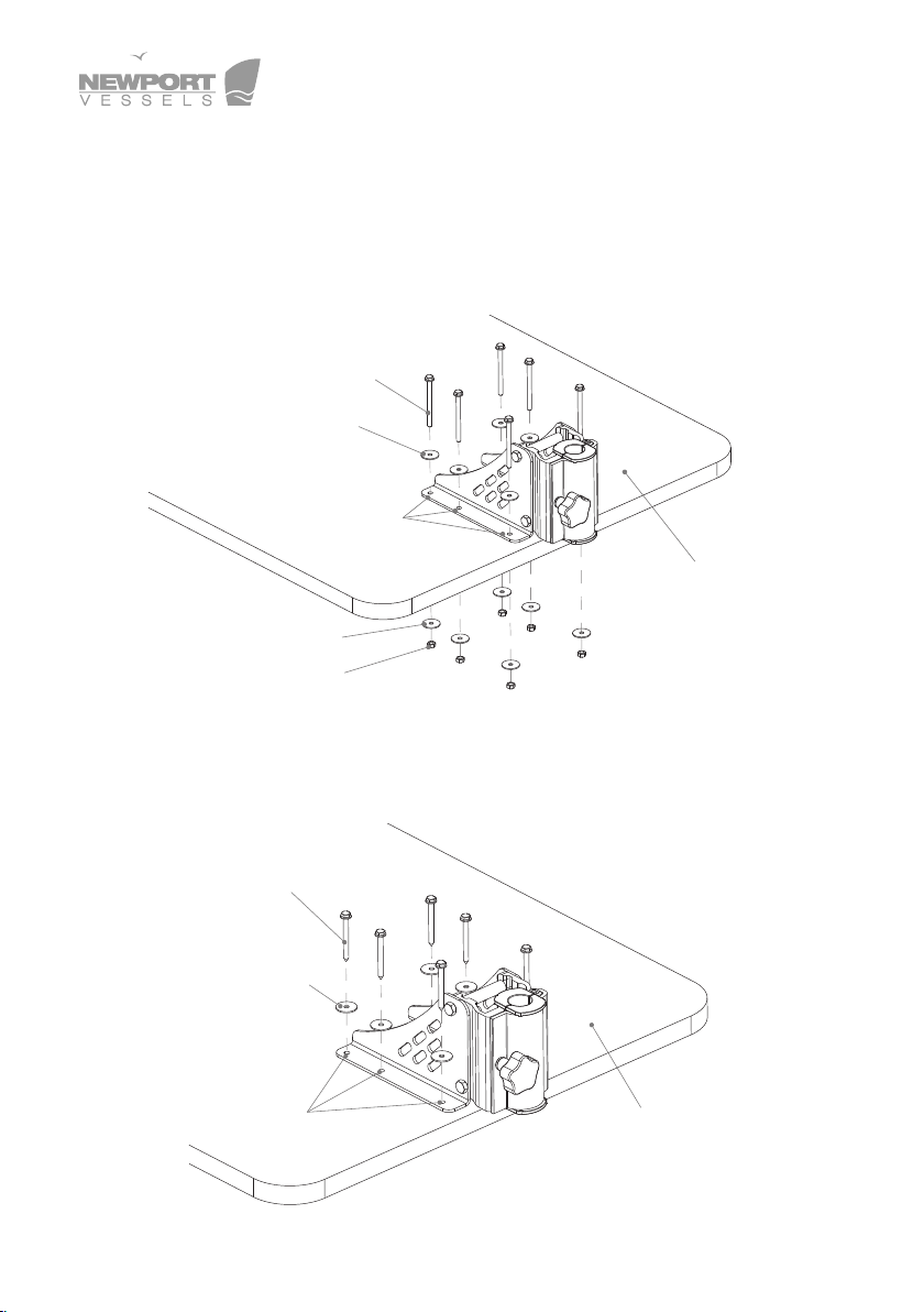
6 Mounting Bracket Installation
We recommend installing the motor along the centerline or keel of the
pontoon boat. Before the installation, remove the motor assembly
first and place the mounting bracket at the desired position.
Before installing the mounting bracket make sure
the motor is disconnected to the battery or other power source.
Deck of Pontoon
Boat Keel
D
Deck of Pontoon
Latch and
Door Closed
Motor Shaft
Motor Depth
Adjusting Collar
Steering Tension
Adjusting Handle

9
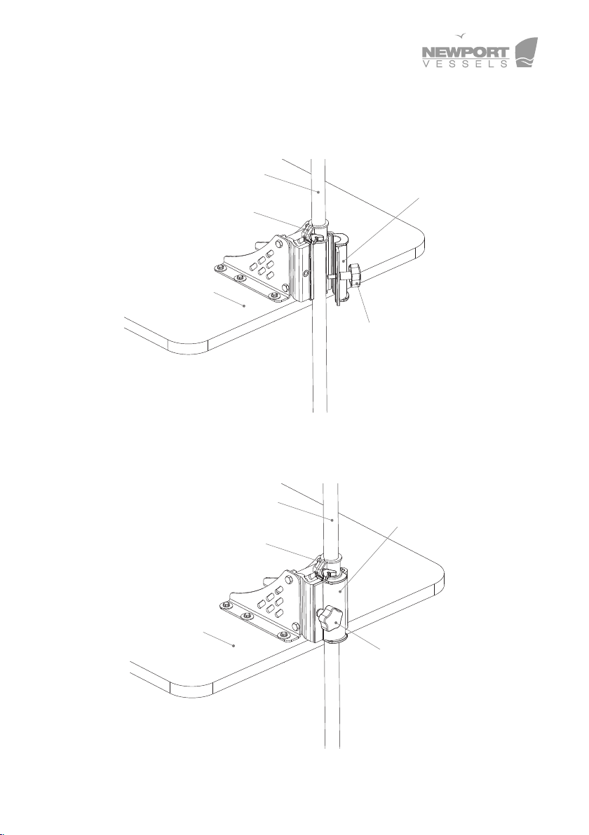
Loosenthe steering tension adjusting handle and open the latch
and door to remove the motor assembly from the mounting bracket.
Closethe latch and door on the mounting bracket and loosely tighten
the steering tension adjusting handle. Place the motor aside.
Mounting Bracket
Deck of Pontoon
Mounting Holes Latch and Door
Steering Tension
Adjusting Handle
Latch and
Door Opened
Motor Shaft
Motor Depth
Adjusting Collar
Steering Tension
Adjusting Handle
Deck of Pontoon
10
You can choose from two options to secure the mounting bracket.
Option1: Drill holes on the deck of the pontoon boat through the
mounting holes on the mounting bracket. Insert the M6 x 75
screws, washers,and nuts as indicated in the diagram below and
tighten the screws to secure the mounting bracket.
Option2: Place the M6 x 60 Self-tapping screws and washersas
shown in the diagram below and tighten the screws directly into the
deck to secure the mounting bracket. (Only for use on deck materials
that can safely accept self-tapping screws.)
M6 x 60 Self -tapping Screws
Washers
Mounting Holes
Deck of Pontoon
Deck of Pontoon
M6 x 75 Screws
Washers
Washers
Nuts
Mounting Holes
11
Loosenthe steering tension adjusting handle to open the latch and
door, and replace the motor assembly inside as shown below,
making sure the motor depth adjusting collar is above the mounting
bracket.
Close the latch and door and tighten the steering tension adjusting han-
dle, making sure the motor assembly is in place properly.
Latch and
Door Opened
Motor Shaft
Motor Depth
Adjusting Collar
Steering Tension
Adjusting Handle
Deck of Pontoon
Deck of Pontoon
Latch and
Door Closed
Motor Shaft
Motor Depth
Adjusting Collar
Steering Tension
Adjusting Handle

12
7 Motor Operation
This product does not include batteries; please choose a battery
with 12V (24V for 86LBS motor output to fit this motor. The
recommended type of battery is a deep cycle battery or marine
battery, as they will last much longer and are specifically designed for
this application.
7.1 Battery Connection Method (12 Volt only)
7.1.1 Connection With One Battery (12V DC)
The red wire should connect to positive; the black wire should
connect to negative. (It is recommended to install circuit breaker on the
positive wire.)
7.1.2 Connection With Two Batteries in Parallel (12V DC)
The red wire should connect to positive; the black wire should
connect to negative. (It is recommended to install circuit breaker on the
positive wire.)
13
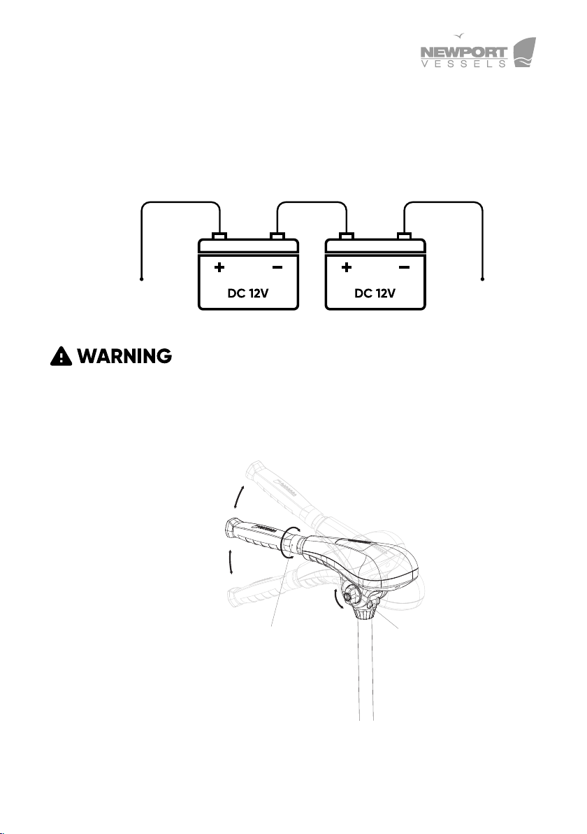
7.3 How To Control The Motor
7.3.1 On/Off Speed Control
Rotate handle clockwise to obtain any of the 5forward speeds. Rotate
7.2 Battery Connection Method (24 Volt only)
7.2.1 Connection With Two Batteries in Series (24V DC)
The red wire should connect to positive; the black wire should connect
to negative. (It is recommended to install circuit breaker in line with pos-
itive lead.)
Remember to always disconnect from the battery(s)
once the motor leaves water as a rotating propeller can cause personal
injury.
Adjustable Handle
Position
Rotate the Handle
to Select Gears
Rotating Tension
Adjusting Knob

14
handle counter-clockwise for any of the 3 reverse speeds. To stop
the motor from running, position the handle matching the arrow marker
on level 0.
7.3.2 Adjust Handle Position
To adjust the position of the handle, loosenthe rotating tension
adjusting knob, adjust to desired position, and then re-tighten. Tighten
the rotating tension adjusting knob to preferred level of resistance,or
all the way to lock the handle.
7.3.3 Battery Level Indicator
There are ten LED lights on the top cover. When seven LED’s are out,
the meter is indicating that the input voltage is less than 9.5V (normal
voltage draw is 12V). At this point it is advised to disconnect the
motor from the battery to prevent damage to the battery and recharge.
7.3.4 Adjusting Motor Depth
Position the depth adjustment collar so the propeller blades are
sub-merged 6inches - 12inches (15cm - 30cm) below the surface of
the water.
7.3.5 Adjusting Steering Tension
Tighten or loosenthe steering tension adjusting handle to increase
or decrease the steering tension. You can also lock the motor direction
by tightening the steering tension adjusting handle firmly.
Remember to wash the motor with fresh water
after being used in salt water,as it can greatly reduce the possibility
of corrosion.
15
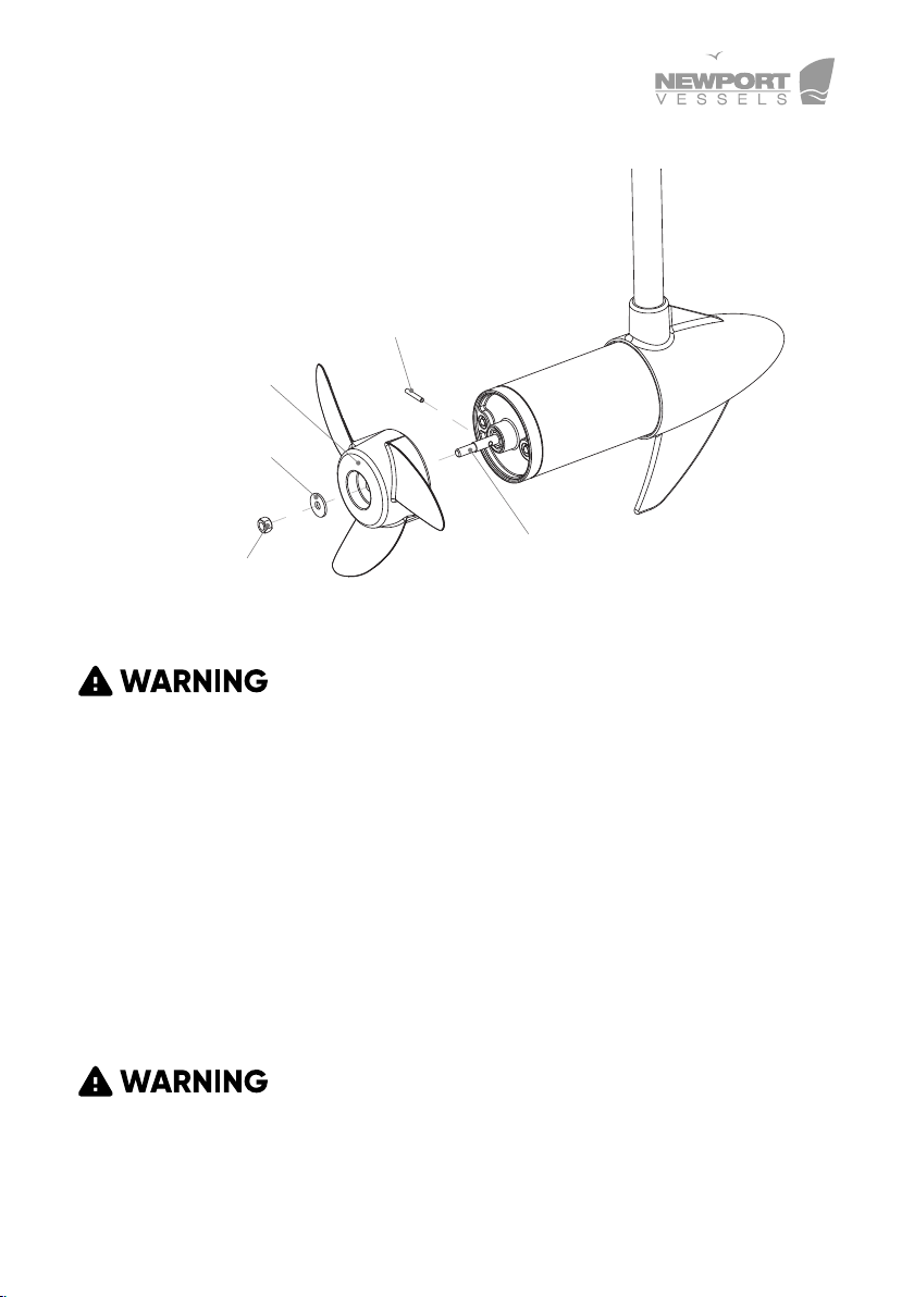
8 How to Replace the Propeller
Make sure that the motor has been disconnected
from batteries before handling the propeller.
Please visit https://newportvessels.com/propeller-installation-
guide/ to get more details.
Hold the propeller blade and loosen the propeller nut using the
prop spanner supplied or a set of needle-nose pliers. Remove the
propeller nut. Pull the propeller straight off. If prop is stuck, grasp one
blade with one hand and tap on the backside of the opposite blade
lightly with a rubber mallet, until the propeller comes off. If the
propeller pin is bent, replace it. Align the new propeller with the
propeller pin. Reinstall the propeller nut and tighten firmly by hand,
then tighten with spanner another 1/4 turn.
Do not strike bent prop pin with hammer to remove
pin. Damage to motor armature may occur that would not be covered
by warranty.
Motor Drive Shaft
Drive Pin
Motor Propeller
Propeller Washer
Propeller Nut

16
9 Daily Maintenance
1. Check behind the propeller after each day for weeds, fishing line or
other debris that may get wrapped behind the propeller.
2. Lubricate all the pivot points with a non-aerosol lubricant. Never
use an aerosol lubricant as many types contain harmful propellants
that can cause damage to various parts of your electric motor.
3. Check tightness of the battery lead connections.
4. Visually check condition of main battery cables.
5. Inspect for loose or corroded wiring connections.
6. Always thoroughly rinse your electric outboard motor with fresh
water after every use in salt water. Only rinse the areas that have
been in contact with salt water, avoid getting the top cover wet as
this may damage the circuitry inside.
7. Inspect tightness of all nuts, bolts and screws.
8. Recharge batteries after each use. Follow the battery manufactur-
er’s recommendations for battery maintenance.
9. During freezing temperatures, when your electric motor is not being
used, it should be stored in an area where it will not freeze.
10. Never connect the wires to the wrong battery terminal. You must
disconnect the battery during maintenance.

17
10 Trouble Shooting
10.1 Loss of Power
•Propeller may be damaged. Remove propeller, clean and replace.
•Battery connections may be corroded.
•Battery has low voltage. Recharge.
•Battery may be faulty, recharge and check.
• Insufficient wire size from battery to motor wiring. 6 gauge wire/
13mm2 thickness recommended.
•Bad or faulty connection in boat wiring or electric motor wiring.
•Permanent magnet cracked or chipped. Motor will whine or grind.
10.2 Motor Makes Excessive Noise or Vibration
•Propeller may be damaged or unbalanced.
•Check to see if propeller is secured.
•Bent armature. Remove propeller, set at medium speed, turn unit on
and check for armature wobble.
•Turn propeller by hand. It should turn freely with a slight magnetic
drag.
•Bearing bushes may be worn out.
10.3 Motor Fails to Run
•Check fuse circuit breaker on boat for electric motor.
•Check for loose or corroded connections.
•Check plug for loose or bad connection.
•Test main rotary switch.
•Turn prop by hand. It should turn freely with a slight magnetic drag.

18
•Total battery failure. Recharge and check voltage.
•Propeller damaged.
10.4 Motor Loses One or More Speeds
•Loose wire on rotary switch. Check wiring diagram.
•Loose connection in top housing.
•Rotary switch damaged.
•Speed coils in lower unit may be burned.
11 About Circuit breaker
During the usage of the electric outboard motor, the propeller
can sometimes get stuck in weeds, fishing lines, or fishing nets.
Sometimes, due to the variance of the water depth, the propeller can
become covered in silt. If those situations occur, quickly disconnect
the battery and clean the propeller. (Please DO NOT increase the
thrust of electric outboard motor to solve the problem, or it may
cause permanent damage to the electric outboard motor.)
The characteristics between the electric outboard motor and gasoline
outboard motor are dierent. If the propeller of the motor gets stuck,
the gasoline outboard motor will shut down to not cause any permanent
damage to the motor itself. However, the electric outboard will draw
extremely large current due to the motor stall and can generate large
amounts of heat that can damage important components in the motor
such as switch, rotor and other connecting parts or even cause serious
battery explosions.
In some muddy water areas, it can be hard for the user to recognize
that the motor is stalled. To prevent these situations from occurring, it
is strongly recommended to use circuit breaker to protect the electric
outboard motor. If the current draw of the electric outboard motor ex-
ceeds the limit of normal usage, the circuit breaker will cut o the power
automatically to prevent any possible damage to the electric outboard

19
motor. The circuit breaker has a reset button and is therefore reusable.
To prevent the rotor coil damage from exceeding current, it is highly rec-
ommended to use a circuit breaker to protect electric outboard motor.
11.1 Function of the circuit breaker
During the usage of the electric outboard motor, when the propeller
is stuck by the weeds, small stones, fishing lines, etc., the circuit
breaker will cut off the power automatically to prevent the damage of
the motor’s electrical parts.
If the circuit breaker cuts off the power, please disconnect the battery
first, then check and clear any obstacles. Finally, press the reset
button on the circuit breaker and reconnect the battery.The electric
outboard motor will now be able to continue functioning properly.

20
12 Declaration of Conformity for Recreational Craft
Propulsion Engine with the requirements of Directive
89/392/EEC as amended by 89/336/EEC.
Engine type approved according to: Directives 89/392/EEC, 89/336/EE
Description of Engine(s) and Essential Requirements
Engine Type: Outboard Engine Fuel Type: Electric
This declaration of conformity is issued under the sole responsibility
of the manufacturer. I declare on behalf of the manufacturer that the
motor(s) is (are) in conformity with the type(s) for which above mentioned
EC, EMC and ROHC type-examination or type approval certicate(s)
has (have) been issued and it will meet the requirements of Directive
89/392/EEC, 89/336/EEC as amended when installed in a recreational
craft, in accordance with the manufacturer’s supplied instructions.
13 Customer Support
If you have questions that are not answered in this manual or trouble-
shooting is not successful, please contact Newport Vessels! Our Cali-
fornia based customer service team is standing by to assist you.
Customer Support
Phone: (866)721-0002
Email: [email protected]
Hours: 8:30am-4:30pm Pacific Time
This manual suits for next models
2
Table of contents


