Suzuki DF140A User manual

1
ENGLISH
DF115A
DF115AS
DF140A
OWNER’S MANUAL
EN

2
California Proposition 65 Warning
IMPORTANT
WARNING/
CAUTION/ NOTICE/
NOTE
Please read this manual and follow its instruc-
tions carefully. To emphasize special informa-
tion, the symbol and the words WARNING,
CAUTION, NOTICE and NOTE have special
meanings. Pay special attention to the mes-
sages highlighted by these signal words.
WARNING
Operating, servicing and maintain-
ing an outboard motor can expose
you to chemicals including engine
exhaust, carbon monoxide, phtha-
lates, and lead, which are known
to the State of California to cause
cancer and birth defects or other
reproductive harm. To minimize
exposure, avoid breathing
exhaust, do not idle the engine
except as necessary, service your
outboard motor in a well-venti-
lated area and wear gloves or
wash your hands frequently when
servicing your outboard motor.
For more information go to
www.P65Warnings.ca.gov.
WARNING
Indicates a potential hazard that could
result in death or serious injury.
CAUTION
Indicates a potential hazard that could
result in minor or moderate injury.
NOTICE
Indicates a potential hazard that could
result in damage to the motor or boat.
NOTE:
Indicates special instructions to make mainte-
nance easier or instructions clearer.
BREAK-IN INFORMATION
FOR YOUR OUTBOARD MOTOR
The first 10 hours are the most important in the
life of your engine. Proper operation during this
break-in period is essential to help ensure max-
imum life and performance.
Refer to the BREAK-IN section of this manual
for specific break-in recommendations.
IMPORTANT NOTICE TO OWNERS
WARNING
Failure to take the proper precautions
may increase the risk of death or severe
injury to you and your passengers.
• Prior to first-time use of your outboard
motor, familiarize yourself thoroughly
with the contents of this owner’s man-
ual. Be aware of all outboard motor fea-
tures and all safety and maintenance
requirements.
• Inspect the boat and motor before each
trip. See the INSPECTION BEFORE
BOATING section for important items.
• Become thoroughly familiar with all
operating and handling characteristics
of your boat and motor. Practice at low
and moderate speeds until you are
competent at handling the boat and
motor. Do not attempt to operate at max-
imum performance until you are com-
pletely familiar with all of these
characteristics.
• Carry boating safety and emergency
equipment. This important equipment
includes; flotation aids for each person
(plus one throwable buoyant cushion in
any boat 16 feet or longer), fire extin-
guisher, sound signaling device, visual
distress signals, anchor, bilge pump,
bucket, compass, emergency starter

3
rope, extra fuel and oil, first aid kit,
flashlight, food and water, mirror, pad-
dles, tool kit, and transistor radio. Be
sure you are carrying the equipment
appropriate for your trip before launch-
ing.
• Never start the engine or let it run
indoors or where there is little or no
ventilation. Exhaust gas contains car-
bon monoxide, a gas that is colorless
and odorless and can cause death or
severe injury.
• Instruct your passengers on how to
operate the boat, how to deal with
emergencies, and how to operate
safety and emergency equipment.
• Do not hold onto the motor cover or
any other parts of your outboard motor
while getting on or off your boat.
• Ensure that everyone wears a PFD (Per-
sonal Flotation Device) on board.
• Never operate the boat while under the
influence of alcohol or other drugs.
• Distribute all weight load evenly in the
boat.
• Have all scheduled maintenance per-
formed. Consult your authorized
Suzuki marine dealer as required.
• Do not modify or remove any outboard
motor standard equipment. To do so
may make the motor unsafe to use.
• Learn and obey all applicable naviga-
tion rules.
• Pay attention to all weather forecasts.
Do not set out if weather is unsettled.
• Use extreme caution when purchasing
replacement parts or accessories.
Suzuki strongly recommends that you
use only genuine Suzuki replacement
parts/accessories or their equivalent.
Inappropriate or poor quality replace-
ment parts or accessories can create
unsafe operating conditions.
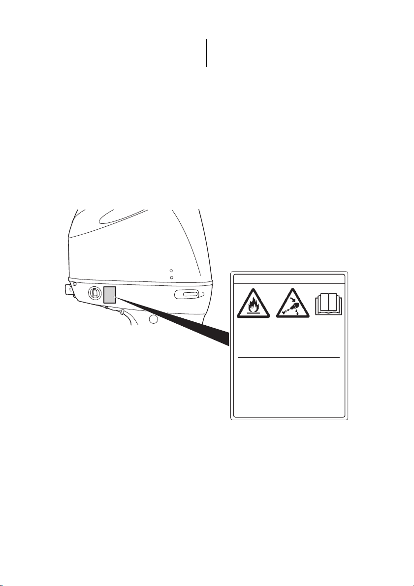
NOTE:
Mounting radio transceiver or navigational
equipment antennae too close to the engine
cowling can cause electrical noise interference.
Suzuki recommends that antennae be mounted
at least one meter (40 inches) away from the
engine cowling.
FOREWORD
The proper care and maintenance that your
outboard motor requires is outlined in this man-
ual. By following these instructions explicitly you
will ensure a long trouble-free operating life for
your outboard motor. This outboard motor also
conforms to the U.S Environmental Protection
Agency emission regulations which apply to
new outboard motors. The proper adjustment of
engine components is necessary for this out-
board motor to comply with the EPA regula-
tions. Therefore, please follow the maintenance
instructions closely to ensure emission compli-
ance. Your Suzuki dealer has experienced tech-
nicians that are trained to provide your outboard
motor with the best possible service with the
right tools and equipment.
All information in this manual is based on the
latest product information available at the time
of publication. Due to improvements or other
changes, there may be discrepancies between
this manual and your outboard motor. Suzuki
reserves the right to make production changes
at any time, without notice and without incurring
any obligation to make the same or similar
changes to outboard motor previously built or
sold.
This manual should be considered a per-
manent part of the outboard motor and
should remain with the outboard motor
when resold or otherwise transferred to a
new owner or operator. Please read this
manual carefully before operating your
new Suzuki and review the manual from
time to time. It contains important infor-
mation on safety, operation, and mainte-
nance.

4
PLEASE PRESERVE NATURE
Protect and preserve your boating waters and
their land access. Never pollute the water or
land with oil, gas, or other harmful products. For
example, make sure you dispose of used gear
oil properly following a gear oil change. Also
remember not to litter. With a little bit of effort,
our boating waters can be enjoyed for many
years to come.
Suzuki Motor Corporation believes in conserva-
tion and protection of Earth’s natural resources.
To that end, we encourage every outboard
motor owner to recycle, trade in, or properly dis-
pose of, as appropriate, used oil and batteries.
TAKE A BOATING SAFETY CLASS
An educated boater will enjoy boating more and
will be a safer boater. We recommend that you
take a boating safety class.
Classes explaining required and recommended
equipment for small boats and offering training
in good seamanship are conducted by the U.S.
Coast Guard Auxiliary, the U.S. Power Squad-
ron, and many Red Cross chapters. For infor-
mation on classes in your area, call toll-free 1-
800-336-BOAT (2628).
Your state’s department of boating and your
Suzuki Marine dealer can supply you with addi-
tional information on boating safety and regula-
tions, or you can call the U.S. Coast Guard
Boating Safety Hotline toll-free at 1-800-368-
5647.
TABLE OF CONTENTS
FUEL AND OIL....................................... 6
GASOLINE............................................ 6
FILLING THE FUEL TANK ................... 7
ENGINE OIL.......................................... 8
GEAR OIL ............................................. 8
LOCATION OF SAFETY LABELS ..... 9
LOCATION OF PARTS....................... 11
MOTOR INSTALLATION.................. 12
EMISSION-RELATED
INSTALLATION INSTRUCTIONS ...... 12
MOTOR INSTALLATION.................... 12
BATTERY INSTALLATION .............. 13
BATTERY REQUIREMENT ................ 13
BATTERY INSTALLATION ................ 13
SUB BATTERY CABLE...................... 14
USE OF ELECTRICAL
ACCESSORIES................................... 14
SUZUKI KEYLESS START SYSTEM
(IF EQUIPPED WITH KEYLESS START
SYSTEM) ................................................. 15
IMMOBILIZER SYSTEM ..................... 15
KEY-FOB............................................. 15
KEY-FOB BATTERY
REPLACEMENT ................................. 17
SETTING AND/OR CHANGING
THE PASSCODE ................................ 19
PASSCODE CONFIRMATION............ 21
PROPELLER SELECTION AND
INSTALLATION................................... 22
PROPELLER SELECTION ................. 22
PROPELLER INSTALLATION ........... 23
ADJUSTMENTS ................................... 24
TRIM ANGLE ADJUSTMENT............. 24
TRIM TAB ADJUSTMENT.................. 25
THROTTLE TENSION
ADJUSTMENT .................................... 26
IDLE SPEED ADJUSTMENT.............. 26
SETTING OF TILT UPPER LIMIT
POSITION............................................ 26
MOTOR COVER FASTENING
ADJUSTMENT .................................... 28
CAUTION SYSTEM............................. 29
INDICATOR CHECK........................... 29
OVER-REVOLUTION CAUTION
SYSTEM.............................................. 30
OIL PRESSURE CAUTION
SYSTEM.............................................. 31
COOLING WATER CAUTION
SYSTEM.............................................. 31
BATTERY VOLTAGE CAUTION
SYSTEM.............................................. 33

5
KEYLESS START SYSTEM CAUTION
SYSTEM (IF EQUIPPED WITH
KEYLESS START SYSTEM)................... 33
KEY-FOB CAUTION SYSTEM ........... 33
KEY-FOB BATTERY CAUTION
SYSTEM.............................................. 34
KEYLESS CONTROL UNIT
CAUTION SYSTEM............................. 34
DIAGNOSTIC SYSTEM...................... 35
OIL CHANGE REMINDER
SYSTEM................................................. 36
SYSTEM ACTIVATION....................... 36
CANCELLATION ................................ 36
ENGINE STALLING CAUTION
SYSTEM................................................. 37
WATER IN FUEL ALERT
SYSTEM................................................. 37
OPERATION OF TILTING
SYSTEMS............................................... 38
POWER TRIM AND TILT.................... 38
MANUAL TILTING .............................. 39
TILT LEVER ........................................ 39
INSPECTION BEFORE BOATING... 41
BREAK-IN ............................................. 43
OPERATION ......................................... 44
MAIN SWITCH (OPTION) ................... 44
BEFORE ATTEMPTING TO START
THE ENGINE....................................... 44
STARTING THE ENGINE ................... 46
EMERGENCY START......................... 50
SHIFTING AND SPEED CONTROL ... 54
STOPPING THE ENGINE ................... 55
MOORING ........................................... 57
OPERATION IN SHALLOW
WATER................................................ 57
OPERATING THE TROLL MODE
(Optional Item) ................................... 58
OPERATION IN SALT WATER .......... 59
OPERATION IN FREEZING
WEATHER........................................... 59
MOTOR REMOVAL AND
TRANSPORTING................................. 59
MOTOR REMOVAL ............................ 59
MOTOR TRANSPORTING.................. 59
TRAILERING........................................ 62
INSPECTION AND
MAINTENANCE................................... 63
NOTICE ............................................... 63
MAINTENANCE SCHEDULE ............. 63
TOOL KIT............................................ 64
SPARK PLUG ..................................... 65
BREATHER AND FUEL LINE ............ 66
ENGINE OIL........................................ 67
GEAR OIL ........................................... 68
LOW PRESSURE FUEL FILTER........ 69
LUBRICATION.................................... 71
CORROSION PREVENTION .............. 72
ANODES.............................................. 72
BONDING WIRES ............................... 73
BATTERY............................................ 73
ENGINE OIL FILTER .......................... 74
SPECIAL CARE FOR MATTE
FINISH PAINT ..................................... 74
FLUSHING THE WATER
ASSAGES............................................... 74
SUBMERGED MOTOR....................... 76
STORAGE PROCEDURE ................... 77
MOTOR STORAGE............................. 77
BATTERY STORAGE......................... 78
AFTER STORAGE ............................... 79
GENERAL INFORMATION............... 79
WARRANTIES (For U.S.A)................. 79
IDENTIFICATION NUMBER
LOCATION.......................................... 79
EMISSION CONTROL
INFORMATION.................................... 80
TROUBLESHOOTING........................ 81
SPECIFICATIONS ............................... 84
CHART OF TOTAL OPERATING
HOURS INDICATION ......................... 85
FLOWCHART OF OIL CHANGE
REMINDER SYSTEM.......................... 85

6
FUEL AND OIL
GASOLINE
Suzuki highly recommends that you use alco-
hol-free unleaded gasoline whenever possible,
with a minimum pump octane rating of 87
((R+M)/2 method). In some areas, the only
fuels that are available are oxygenated fuels.
Oxygenated fuels which meet the minimum
octane requirement and the requirements
described below may be used in your outboard
motor without jeopardizing the New Outboard
Motor Limited Warranty.
NOTE:
Oxygenated fuels are fuels which contain oxy-
gen-carrying additives such as alcohol.
Suzuki recommends that you install a water-
separating fuel filter assembly between your
boat’s fuel tank(s) and outboard motor(s). Fuel
filtration systems of this type will help prevent
water that may be present in your boat’s fuel
tank(s) from contaminating your motor’s elec-
tronic fuel injection system. Water contamina-
tion can cause poor engine performance and
can also cause damage to the electronic fuel
injection system components.
Your Authorized Suzuki Marine Dealer can pro-
vide you advice about water-separating fuel fil-
ter systems and installation.
NOTICE
Use of leaded gasoline can cause engine
damage. Use of improper or poor quality
fuel can affect performance and may
damage your motor and fuel system.
Use only unleaded gasoline. Do not use
fuel having lower than the recommended
octane, or fuel that may be stale or con-
taminated by dirt/water etc.
Gasoline/Ethanol Blends
Blends of unleaded gasoline and ethanol (grain
alcohol), also known as gasohol, may be used
in your outboard motor if the ethanol content is
not greater than 10%.
Fuel Pump Labeling
In some states, pumps that dispense oxygen-
ated fuels are required to be labeled for the type
and percentage of oxygenate, and whether
important additives are present. Such labels
may provide enough information for you to
determine if a particular blend of fuel meets the
requirements listed above. In other states,
pumps may not be clearly labeled as to the con-
tent or type of oxygenate and additives. If you
are not sure that the fuel you intend to use
meets these requirements, check with the ser-
vice station operator or the fuel suppliers.
NOTE:
• Be sure that any oxygenated fuel blend you
use has octane ratings of at least 87 pump
octane ((R+M)/2 method).
• If you are not satisfied with the driveability or
fuel economy of your outboard motor when
you are using a gasoline/alcohol blend, you
should switch back to unleaded gasoline con-
taining no alcohol.
• If engine pinging is experienced, substitute
another brand, as there are differences
between brands.
• Unleaded gasoline will extend spark plug life.
NOTICE
Gasoline kept in the fuel tank for long
periods of time will produce varnish and
gum, which can damage the engine.
Always use fresh gasoline.

7
FILLING THE FUEL TANK
To fill the fuel tank:
1. Always stop the engine before refilling the
tank.
2. Remove the portable fuel tank from the boat
to refill it.
WARNING
Gasoline is extremely flammable and
toxic. It can cause a fire and can be haz-
ardous to people and pets.
Always take the following precautions
when refueling:
• Never permit anyone other than an
adult to refill the fuel tank.
• If you use a portable fuel tank, always
stop the motor and remove the fuel
tank from the boat to refill it.
• Do not fill the fuel tank all the way to
the top or fuel may overflow when it
expands due to heating by the sun.
• Be careful not to spill fuel. If you do,
wipe it up immediately.
• Do not smoke, and keep away from
open flames and sparks.
NOTICE
Fuels containing alcohol can cause paint
damage, which is not covered under the
New Outboard Motor Limited Warranty.
Be careful not to spill fuel containing
alcohol while refueling. If fuel is spilled,
wipe it up immediately.
3. Turn the air-vent screw 1on top of the fuel
tank cap 2fully counterclockwise to open
the vent.
NOTE:
VENT SCREW should be CLOSED for trans-
portation and OPEN for OPERATlON and CAP
REMOVAL.
4. Locate the pressure relief tab 3under the
fuel tank cap and turn the cap counterclock-
wise until the tab engages the first lock.

8
5. Press down on the tab, and release the lock,
then rotate the fuel tank cap 1/4 turn. The
tab will engage the second lock.
6. Press the tab down again and turn to
remove the fuel tank cap.
7. Carefully refill the fuel tank with gasoline.
Do not over fill.
8. Tighten the fuel tank cap until an audible
“click” is heard.
9. Tighten the air-vent screw on top of the fuel
tank cap.
ENGINE OIL
Oil quality is a major contributor to your
engine’s performance and life. Always select
good quality engine oil.
Suzuki recommends the use of SAE 10W-40 or
10W-30 SUZUKI MARINE 4-CYCLE ENGINE
OIL. If SUZUKI MARINE 4-CYCLE ENGINE
OIL is not available, select a NMMA certified
FC-W oil or good quality 4-cycle motor oil from
the following chart according to the average
temperatures in your area.
NOTE:
In very cold weather (below 5°C (41°F)), use
SAE (or NMMA FC-W) 5W-30 for easier start-
ing and smooth operation.
GEAR OIL
Suzuki recommends the use of SUZUKI
HYPOID GEAR OIL. If it is not available, use
SAE 90 hypoid gear oil which is rated GL-5
under the API classification system.
NOTICE
Use of poor quality engine oil can
adversely affect engine performance and
life.
Suzuki recommends that you use Suzuki
Marine 4-Cycle Engine Oil (ECSTAR) or
its equivalent.
–20 –10 0 10 20 30
–4 14 32 50 68 86
40
104
TEMP.
API Classification
SAE Viscosity Grade
10W–40
10W–30
˚F
˚C
SG
SH
SJ
SL
SM
SN

9
LOCATION OF SAFETY LABELS
Read and follow all of the labels on your out-
board motor or fuel tank. Make sure you under-
stand all of the labels.
Keep the labels on your outboard motor or fuel
tank. Do not remove them for any reason.
WARNING
AVERTISSEMENT
8
• Fuel can leak creating a fire hazard if
you lay motor on its side. Drain fuel
completely from vapor separator or
carburetor before laying motor on its side.
• See owner’s manual for details.
• Le carburent risque de fuir et de
présenter un danger d’incendie si le
moteur est placé sur le côté.
Vidanger entièrement le carburant du
séparateur de vapeurs ou du
carburateur avant de procéder.
• Pour plus de détail, voir le manuel
du propriétaire.

10
Label symbol meanings
These symbols mean as follows;
: General warning symbol
(Caution or Warning)
: Read owner’s manual carefully
: Remote control lever/gear shift
lever operation-two direction;
Forward/Neutral/Reverse
: Engine start
: Hazard caused by fire
: Hazard caused by laying
the motor on its side

11
LOCATION OF PARTS
MONITOR-TACHOMETER
SIDE MOUNT TYPE
TOP MOUNT TYPE
REMOTE CONTROL BOX (Option)
Engine oil drain plug
Clamp bracket
Anode
Gear oil level plug
Water intake hole
Gear oil drain plug
Power trim and tilt
(P.T.T.) switch
(Reverse side)
Motor cover
Pilot water hole
Flush plug
(Reverse side)
Anti-cavitation plate
Trim tab
KEY-FOB
(IF EQUIPPED WITH
KEYLESS START SYSTEM)
PRIMING BULB
EMERGENCY
PUSH
START
STOP
START Ignition key
Emergency
stop switch Emergency
stop switch
Main switch
If not equipped with
keyless start system If equipped with
keyless start system
Power trim and tilt
(P.T.T.) switch
Remote control
handle
Free accelerator button
Main switch (If equipped
with Keyless Start System)
Ignition key (If not equipped
with Keyless Start System)
Emergency stop switch
Remote control handle
Warm-up lever
Power trim and tilt
(P.T.T.) switch
Throttle tension adjuster
Lock-out
lever

12
MOTOR INSTALLATION
EMISSION-RELATED INSTALLATION
INSTRUCTIONS
Fuel lines and fuel tanks used for a vessel must
meet the requirements of federal law (40 CFR
1045.112 and 40 CFR 1060).
lf you install the engine in a way that makes the
engine’s emission control information label hard
to read during normal engine maintenance, you
must place a duplicate label on the vessel, as
described in 40 CFR 1068.105.
Failing to follow these instructions when
installing a certified engine in a vessel vio-
lates federal law (40 CFR 1068.105(b)), sub-
ject to fines or other penalties as described
in the Clean Air Act.
MOTOR INSTALLATION
NOTE:
It is against federal regulations for any marine
dealer to service a motor that exceeds the rec-
ommended maximum horsepower for your
boat.
Suzuki strongly recommends that you have
your outboard motor, controls and gauges
installed by your authorized Suzuki Marine
Dealer. He has the tools, the facilities and the
know-how.
WARNING
Overpowering your boat can be hazard-
ous. Excessive horsepower will have an
adverse effect on hull safety and may
cause operating/handling difficulties. The
boat may also sustain stress and hull
damage.
Never install an outboard motor with
horsepower exceeding the manufac-
turer’s recommended maximum horse-
power listed on the boat’s “Certification
Plate”. Contact your authorized Suzuki
marine dealer if you are unable to locate
the hull “Certificate Plate”.
WARNING
Failure to have your outboard motor and
associated controls and gauges properly
installed can result in personal injury or
damage.
Suzuki strongly recommends that you
have your outboard motor, controls and
gauges installed by your authorized
Suzuki marine dealer. He has the tools,
the facilities, and the know-how to do the
job correctly.

13
BATTERY INSTALLATION
BATTERY REQUIREMENT
650 Marine Cranking Amps (MCA)/ABYC,
or 512 Cold Cranking Amps (CCA)/SAE
or 160 Reserve Capacity (RC) Minutes/SAE
NOTE:
• The specifications listed above are the mini-
mum battery rating requirements for starting
the engine.
• Additional electrical loads from the boat will
require larger capacity batteries. Consult
your Suzuki dealer to determine the proper
battery sizing for your boat and engine com-
bination.
• Dual-purpose (Cranking/Deep-cycle) batter-
ies can be used if they meet the minimum
specifications listed above (MCA, CCA, or
RC).
• Do not use a Deep Cycle battery for the main
cranking battery.
• When connecting batteries in parallel, they
must be of the same type, capacity, manufac-
turer, and of similar age. When replacement
is necessary, they should be replaced as a
set. Consult your Suzuki dealer for proper
battery installation information.
BATTERY INSTALLATION
Secure the battery in a dry area of the boat,
away from vibration.
NOTE:
• It is recommended that the battery be
installed in an enclosed battery case.
• When connecting batteries, hexagon-nuts
must be used to secure battery leads to bat-
tery posts.
To hook up the battery, first connect the red
lead from the motor to the positive battery ter-
minal, then connect the black lead to the nega-
tive battery terminal.
WARNING
If you place the battery near the fuel tank,
a spark from the battery may ignite the
gasoline, causing a fire and/or an explo-
sion.
Do not place the fuel tank in the same
compartment/area as the battery.
Red lead Sub battery cable
Black
lead
White lead
Hexagon-nut

14
To remove the battery, first disconnect the black
lead from the negative terminal, then discon-
nect the red lead from the positive terminal.
Connecting and disconnecting the battery as
described above will help minimize the chance
of creating an accidental short circuit and
sparks.
Suzuki recommends that you install the termi-
nal cap on the positive battery terminal to pre-
vent an accidental short circuit of battery
terminals.
If a terminal cap is required, contact your autho-
rized Suzuki marine dealer.
WARNING
Batteries produce flammable hydrogen
gas and may explode if they are near
flames or sparks.
Never smoke or cause sparks when work-
ing near the battery. Keep the battery
away from open flames. To avoid creating
a spark when charging the battery, con-
nect the battery charger cables to the
proper terminals before turning the
charger on.
WARNING
Battery acid is poisonous and corrosive.
It can cause severe injury and can dam-
age painted surfaces.
Avoid contact with eyes, skin, clothing,
and painted surfaces. If battery acid
comes in contact with any of these, flush
immediately with large amounts of water.
If acid contacts the eyes or skin, get
immediate medical attention.
SUB BATTERY CABLE
The sub battery cable 1is used to supply volt-
age to the engine control system. In the midst
of the cable, a 15 A fuse 2is provided to pro-
tect the control circuit.
If the sub battery cable is not correctly con-
nected to the battery, engine cannot be started.
USE OF ELECTRICAL ACCESSORIES
The amount of power (12V DC) available for
accessories depends on the operating condi-
tion of the motor. For getting a detailed informa-
tion, please inquire of your authorized Suzuki
Marine Dealer.
NOTE:
Use of too much power for electrical accesso-
ries under certain operating conditions can
cause the battery to discharge.
NOTICE
The electrical system or its components
may be damaged if proper battery pre-
cautions are not followed.
• Be sure to attach battery leads cor-
rectly.
• Do not disconnect battery leads from
the battery while the engine is running.

15
SUZUKI KEYLESS START
SYSTEM
(IF EQUIPPED WITH
KEYLESS START SYSTEM)
This system allows you to start the engine by
means of communication between the key-fob
and the keyless control unit when you have the
key-fob with you, instead of using the mechani-
cal key.
The engine can be started when the distance
between the key-fob and the keyless control
unit is within the communication range of 1 m
(39.4 in).
In addition, this system is equipped with immo-
bilizer feature.
NOTE:
Please consult with a Suzuki Marine Dealer for
the installation of the Keyless Start System.
Also refer to the “Keyless Start System Instruc-
tion Manual” supplied with the product for
detailed operating instructions.
IMMOBILIZER SYSTEM
In this system, the key-fob and the keyless con-
trol unit uses radio communication to check if
the key-fob ID is registered in the Keyless Start
System.
If the key-fob ID is not registered, the system
prevents the engine from starting using the key-
fob.
Key-fob
Keyless control unit
KEY-FOB
Two (2) key-fobs are supplied with the Keyless
Start System.
NOTE:
The key-fob falls under the category of
restricted electronic devices for use in flight.
WARNING
Radio waves from the keyless control
unit may interfere with the operation of
electrical medical equipment such as
pacemakers. Failure to take the precau-
tions listed below can increase the risk of
severe injury or death due to radio wave
interference.
Anyone who uses electrical medical
equipment such as a pacemaker should
consult the medical equipment supplier
to inquire if radio waves from the keyless
control unit can interfere with the medical
equipment.
WARNING
The key-fob emits radio waves that may
interfere with aircraft operations.
Do NOT operate the buttons on the key-
fob while you are in flight. When putting
the key-fob in a bag, etc., protect the but-
tons from accidently being pressed.

16
NOTICE
The radio waves emitted from the key-fob
may cause interference with other wire-
less communication devices such as
mobile phones and remoter controllers.
Do not operate the buttons on the key-fob
more than necessary.
CAUTION
Attempting to disassemble (except for
battery replacement), repair, or modify
the key-fob may cause ignition, electric
shock, or injury.
Do NOT attempt to disassemble (except
for battery replacement), repair, or modify
the key-fob.
NOTICE
The key-fob is comprised of sophisti-
cated electronic components that can
become damaged and may fail to func-
tion properly if you do not take proper
precaution.
• Do NOT leave it in places that may
reach a high temperature.
• Do NOT apply a strong impact, such as
dropping it.
• Do NOT bring it close to any magnetic
objects.
• Do NOT place it near any electro-mag-
netic devices such as a television or
audio equipment.
• Do NOT place it near any electric medi-
cal equipment (microwave therapy
equipment, low frequency therapy
equipment, etc.), or receive medical
treatment with the key-fob in your
pocket, etc.
NOTE:
• Do NOT erase or tamper with the conform-
ance certification mark.
• A maximum of six (6) key-fobs can be regis-
tered in one keyless control unit.
• The battery life of the key-fob is about two (2)
years, which can vary depending on use.
• The key-fob is always in transmission mode
in order to communicate with the keyless
control unit. For this reason, the battery may
run down quickly if it receives strong radio
waves from televisions or personal comput-
ers, etc.
NOTE:
• The emergency key should be carried sepa-
rately from the key-fob to avoid losing both of
them at the same time.
• If the key-fob and the emergency key are lost,
immediately contact your authorized Suzuki
Marine Dealer.
• The key-fob uses a weak radio wave that is
susceptible to external influences when it
communicates with the keyless control unit.
For this reason, it may not operate properly
under the following use environment.
– There is a nearby facility that emits strong
radio waves such as a television tower,
electric power plant, or broadcasting sta-
tion, etc.
– The key-fob is held close to other wireless
communication devices such as mobile
phone, radio equipment or a laptop per-
sonal computer.
– The key-fob is in contact with or covered
with a metallic object.
NOTE:
• Side mount type remote control box:
One (1) emergency key is included in the
remote control box for the Keyless Start Sys-
tem.
• Top mount type remote control box:
One (1) emergency key is included in the
main switch panel for the Keyless Start Sys-
tem.

17
Switching the communication mode of
the key-fob
Press and hold the lock button 1on the key-fob
for more than one second to switch between
ON mode and OFF mode.
NOTE:
If the lock button is pressed briefly while in com-
munication ON mode, the LED 2on the key-
fob briefly flashes once.
KEY-FOB BATTERY REPLACEMENT
WARNING
As the lithium disc type battery is small, a
child may swallow it by mistake, resulting
in serious internal injury.
Keep the lithium disc type battery out of
reach of children. If someone swallows a
lithium battery, contact a physician imme-
diately.
CAUTION
There is a danger of explosion if the bat-
tery is replaced with an incorrect type.
Only replace the battery with the same or
equivalent type.
If the key-fob battery runs low, the red CHECK
ENGINE lamp will flash.
To replace the key-fob battery:
1. Insert a flat blade screwdriver in the slot of
the key-fob and remove the cover.
NOTICE
To prevent damage to the key-fob, be
careful when replacing the battery.
• Install the lithium disc-type battery with
the electrodes facing the proper direc-
tion.
• Do NOT touch the internal circuit of the
key-fob when replacing the battery.

18
2. Remove the O-ring 1.
NOTE:
The O-ring may be fitted on the cover side.
3. Insert a flat blade screwdriver into the slot at
the mark on the cover to remove the bat-
tery.
NOTICE
If the O-ring is damaged, the waterproof
performance deteriorates, which can
cause the key-fob to malfunction.
Be careful not to damage the O-ring when
removing it.
4. Replace the battery so its +terminal faces
the cover side as shown in the illustration.
Lithium disc type battery: CR2025 or equiva-
lent.
Confirm that the O-ring is placed in position
on the body side.
5. Reinstall the cover.

19
SETTING AND/OR CHANGING THE PASS-
CODE
By setting a 4-digit passcode, the engine can
be started by entering the passcode even if the
key-fob battery has run down or the key-fob is
lost.
The same method is used to set and change
the passcode.
NOTE:
Carry the passcode with the emergency key in
case the key-fob battery runs down or the key-
fob is lost.
NOTE:
When the passcode has been updated or
changed, the previous passcode is deleted and
updated to the new passcode.
Use the following procedure to set or change
the passcode:
1. Confirm the engine is stopped.
2. Make sure the emergency switch lock plate
is in place.
3. Confirm the key-fob is within the communi-
cation range of the Keyless Start System.
4. Confirm that the key-fob is in communication
ON mode. (Refer to “Switching the commu-
nication mode of the key-fob” section.)
5. Turn the main switch to the “ON & OFF”
(“ ”) position and then release it. The main
switch automatically returns to the “PUSH
START/STOP” position.
The buzzer on the engine control side emits
one (1) long sound while the buzzer on the
keyless control unit side emits two (2) short
sounds simultaneously.
ON & OFF ON & OFF
PUSH
START
STOP
PUSH
START
STOP
If equipped with side mount type
remote control box:
6. Pull out the emergency stop switch lock
plate.
7. Within eight (8) seconds after performing
Step 5, start the following operation.
(1)Turn the main switch to the “ON & OFF”
(“ ”) position and hold it for about five (5)
seconds then release it to the “PUSH
START/STOP” position.
Repeat this operation for two more times.
The buzzer sounds once and the system
enters stand-by mode for passcode input.
NOTE:
The buzzer will not sound if the operation in
Step (1) is not performed within eight (8) sec-
onds or the operation fails.
PUSH
START
STOP
PUSH
START
STOP
If equipped with top mount type
remote control box: (Main switch panel)

20
(2)Within 60 seconds after performing Step (1),
turn the main switch to the “ON & OFF”
(“ ”) position and then release it. The main
switch automatically returns to the “PUSH
START/STOP” position.
The buzzer starts emitting short sounds.
Briefly turn the switch after the number of
sounds that is the same as the first pass-
code digit. For example, if the first passcode
digit is seven, turn the switch after the sev-
enth sound.
To set or select zero (0), turn the switch after
the 10th sound.
NOTE:
If the operation in Step (2) is not performed
within 60 seconds after performing Step (1), the
passcode input operation will be cancelled and
the buzzer will sound three (3) times.
ON & OFF ON & OFFON & OFF
PUSH
START
STOP
PUSH
START
STOP
Hold it for five (5) seconds.
*If equipped with top mount type
remote control box: (Main switch panel)
“ON & OFF” “ ”
1234567891011
Example: When entering 7
ON & OFF ON & OFF
PUSH
START
STOP
PUSH
START
STOP
After the buzzer emits 10 sounds, it emits one
long sound before to returning to stand-by
mode for the second passcode digit.
(3)Repeat Step 2 to enter the second, third and
fourth passcode digits.
(4)After entering the fourth pass code digit, the
buzzer emits one continuous sound – within
60 seconds, turn the switch ON and hold it
for five (5) seconds until the buzzer stops,
then release it.
NOTE:
The buzzer emits one (1) short sound for the
1st digit, two (2) short sounds for the 2nd digit,
three (3) short sounds for the 3rd digit, and four
(4) short sounds for the 4th digit.
NOTE:
• If a passcode is not entered during the 10
sounds, the process will start over again after
briefly turning the switch.
• If the main switch is not turned to select a
passcode number after repeating the pass-
code input operation three (3) times, the input
operation is cancelled.
In this case, the buzzer emits short beeps for
five (5) seconds to notify that the input opera-
tion has been cancelled.
• If the passcode input operation has been per-
formed multiple times, the last passcode
entered will become effective.
• To interrupt passcode input, install the lock
plate on the emergency stop switch.
Buzzer sound
When entering
the 1st digit
When entering
the 2nd digit
When entering
the 3rd digit
When entering
the 4th digit
This manual suits for next models
2
Table of contents
Other Suzuki Outboard Motor manuals

Suzuki
Suzuki DF115BG 2021 User manual

Suzuki
Suzuki DF 25 User manual

Suzuki
Suzuki DF70A User manual

Suzuki
Suzuki GF60A User manual

Suzuki
Suzuki DF 140 User guide

Suzuki
Suzuki DF150AP User manual

Suzuki
Suzuki DF200 User manual

Suzuki
Suzuki DF40A User manual

Suzuki
Suzuki DF9.9B User manual

Suzuki
Suzuki DF 30 User manual

Suzuki
Suzuki DF150AP User manual

Suzuki
Suzuki DF 25 User manual

Suzuki
Suzuki DF250AP User manual

Suzuki
Suzuki DF40ASV User manual

Suzuki
Suzuki DT2 User manual

Suzuki
Suzuki DF200 User manual

Suzuki
Suzuki DF350A User guide

Suzuki
Suzuki DF150 User manual

Suzuki
Suzuki DF 25 User manual

Suzuki
Suzuki DF70A User manual