Eaton viking 5D14V User manual

OWIIER
GUIDE
OP[RATION
. IIAI}IT[I{A}I(T
. PARTS1I5T
EATON'S
Irt
lr
ll
{l KI
5 H.P.
DE
1UXT
OUIBOARD
it0T0R
NODE I
5D14Y
HORSEPO\/YER
. 5.0AT 4OOO
R.P.M. _ O.B.C. CERTIFIED
NUMBER OF CYLTNDERS. 2
BORE AND STROKE . t_ts/16" BORE X I t/2" STROKE
PISTON DISPLACEMENT . 8.84
CUBIC INCHES
TYPE OF POWER
HEAD . 2 CYCLE, 2 PORT, ALTERNATE FIRING
GEAR RATIO 15:26
PROPELLER . 2 BLADE, 8n DTAMETER
X7-1/4r pfiCH
COOLING . RUBBER BLADE COMBINATION DISPLACEMENT
ANO CENTRIFUGAL WATER PUMP
ffi*,f .r'#r\-
gi i,;p*
nsi , r
l,l* *-T-
.[ k*--**
1.--: 1 ,1*.
'i. g""W*
!h: t t"r
I.#li
-....*
vtK $
F,t
fi
CARBURETOR
SPEED
CONTROL
IGNITION BUILT IN FLYWHEEL MAGNETO
. FLOAT FEED, HIGH AND LOW SPEED
ADJUSTMENT, AUTOMOTIVE TYPE CHOKE
, SYNCHRONIZEO SPARK AND THROTTLE,
TWIST GRIP CONTROL
FUEL TANK CAPACITY . .t . . 0.7 GALLONS
RUNN]NG TIME (FULL THROTTLE) APPROX. I HOUR
STARTER AUTOMATTC REWIND
GEARSHIFT CONTROL . FORWARO_NEUTRAL_REVERSE
WEIGHT. . 52 PoUNDs
RECOMMENOED TRANSOM HETGHT t5,,
I Monufoctured
erpresslyfor
I
igT,
EATON C?,",,,0
Outboad
lTlarine
hrporotionof Cono/o
ltd
0trte,r0L0UGH
- (AtADA 4O2402_REVIsED

STARTER HANDLE
STEERING
HANDLE
THROTTLE CONTROL
EXHAUST
TUBE
COVER
WATER OUTL.ET
ANTI_CAVITATION
PLATE
FUEL TANK
CAP
PROPELT^ERCAP
FUEL TANK
EXHAUSTOUTLET
WATER INLET
ot[. F
lL-r."
FLL'G
GEAR CASE ---
'i l-
hk
.$rr
&'\- pRopELLER
SKEG
OIL DFAIN PLUG
'TAR'OARO (RIGHT), PORT (LETY) AR€ OEgICiATEO WXILI FACIXO lOW
\--t ----='
Low
SPEED
**or.. *t$
CHOKE KNOB
HIGH SPEEO KNOB
CLAMP SCREW
STERNBRACKET
WATER
PUMP
HOUSING
TIGURE
T
NOTE
ALL BOATSEXEMPT FROM REGISTRYAND POWERED
BY MOTORS
OF 10H.P.
OR MORE MUST BE LICENSED. APPLICATIONFORMSFORBOA* !-!E'.:'{SING
MAY BE OBTAINED FROM YOURNEAREST COLLECTOR OF CUSTOMS OFFICE.

FOREWORD
You are to be congratulated on your selection of this outboard motor which wiII
give you years of satisfactory service. The fine materials and high standards
of workmanship used in the manu-facture of this motor assure you of durabilitv and
lasting performance.
Read through this manual carefully before operating the motor. You will find
complete operating instructions and recommendations for the c:rre and proiectiol
of your motor. Extend the same care to this motor you wcluld give to a new
automobile or other personal property of even less value anciit wilt be a constant
source of satisfaction to you. care in handLing will prevent scratches and
nicks which will mar the appearance.
The operating instructions are concise and easy to follow. even for the begipner..
But if you have never operated an outboard motor, it wili ite helpful to practice
the step by step procedure a few times befclre
ytutting
the motor in agtual i)tlera-
tion.
outboarding is great sport. Always remember, lrowever, that you havc friends
on the water. Extend to them the'courtesy of thoughtful. safe operation of ysur
motor and boat and you will increase your own enj<,ryment.
ANACHING
MOTOR
TOBOAT
Figure 2
ANGLE
ADJUSTING LEVER
lOO
CUT OFF.'
T
I
VERTICAL
TRANSOM
HEIGHT FROM
BOAT
BOTTOM
tf,
This motor is clesigneci
for use orra standard 15-inr.h
transorr,. I{ transom is higher, it sh(,uld be <:ut
down to 15 inches sci propeller wiil be at leusl 2
inches below bottoni of boat. Bt'st perfornrant'e wili
be obtained by having the drivesh:rft vertrc:il to l:oat
travel and the propeller placed beiow l;,ottorn
oI the
boat (see Figure 2,1. Performance c:tn o{ten be inr-
proved by cutting olf the keel at a 10" anrr,ler
es illus-
trated. This will prevcnt iorrnution of spra5,.and
provide free running perf'..ir-rnlncc.
Place motor on stern of boat with ster.n brackel
clamps inside the stern. r:entered
on thc lrirrrst_rll
or
stern board. f ighten brar:liet r:larnp
srrrLrws
st-t:urel\
by hand.
CAUTION
When motor is runnitlg, oc(:usiolutii-r'
chet,k
bracket cl:rmp screws to be sure thev are
tight. We will not Lle resl,rorrs.ible
1or eny
motor danurged ()r lr;,st ovet'lrplrrd r.luc to
loose clamp scrL5ws.
The use of a safety chairr or r'(rpe
illIli('ll(,ci
tr; nrr;tor
stern bracket salety chain Iink (ilern 1, F-iguli, l.r
and boat will guard against krss of nloi.or
over,Li<;urd.
Holes are provided in thumb screw htrrrclles
thrr,ugh
which a padlock nral be appliecl
to lot'k ll-,t'rnutur.or]
the boat.
MAXIMUM
TRANSOM
THICKNESS
1 3
/4"
---f
L- 12OANGLE

OPERATION
ANGLE
ADJUSTMENT
A simple means is provided for adjusting the motor
to a vertical position to make allowance for angle
of the transom.
To accomplish this adjustment, tilt the motor slightly
(gear shift lever must bein FORWARDoTNEUTRAL),
then lift up on angle adjustment lever (see item 5,
Figure 5) and move it ahead or back in the slots in
the stern bracket so that motor is in a vertical posi-
tion when lower unit rests against the Iever. On some
boats it may be necessary to correct angle adjust-
ment to maintain motor in a vertical position when
changing load from one to more passengers. Always
try to arrange load so boat runs on an even keel.
Transom (stern) angles may vary somewhat; how-
ever, range of adjustment is sufficient to accommo-
date angles found in most boats.
Figure3
GIARSH
IFI'
The motor is equipped with gear shift control to
provide operation of the motor in Forward, Neutral,
or Reverse by means of a gearshift lever (Figure 4)
located on side of motor below the tank. Move the
lever as far as possible toward front of tankfor
"Forward" motion of boat -- toward rear of tank as
far as possible for "Reverse" motion of boat. The
intermediate position is "Neutral" or out of gear.
Whenmotor isnotrunning
the
internal
gear
shiftmech-
anism may be in sucha positionthat gear shiJtlever
cannotbe moved from "Neutral" into "Forward" or
"Reverse"
--- DO
NOTFORCE. This may bereme-
died
bypulling
on
thestartercordwiththrottlecontrol
at STOP
to turn gears slightlyuntilthe
gear
shiftlever
will move to desired position. Extreme care should
be taken to prevent bendingor striking the lever.
2
OFYOURTYIOIOR
REVERSE
Always retard motor speed to within "shiitirul rang.c"
as indicated on throttle control plale before siiilting.
A special reverse lock (item 4, Figure 5) built into
the swivel bracket }ocks the motor against tilting
when in reverse. Use extra care when running in
reverse to avoid striking any obstruction and clarn-
aging lower unit parts. The tilting featurefunctions
only in FORWARD or NEUTRAL gear shift position.
LUBRICATION
AND
FUELINSTRUCTIONS
Proper lubrication is an important factor in the per-
formance and life of your outboard motor. The
following instructions are therefore very important
and should be followed carefully.
The oil and fuel mixture referred to in the following
instructions should always be thoroughly mixed in a
separate container before pouring into motor fuel
tAnK: NEVER POUR SEPARATELY INTO FUEL
TANK. AIso, aII fuel should be poured through a
fine mesh strainer to remove dirt and water which
may be present: Use only metal containers.
TYPE OF GASOLINE. Use a good grade of regular
gasoline.
TYPE OF OIL. Use a high grade outboard oil . or,
if that is not available, regular SAE 30 motor oil.
Avoid use of low-priced, third grade (ML) oils.
MIXTURE. Mix 112 pint of oil with each gallon of
gasoline.
PROCEDURE. Pour into the container approximately
one-half the amount of gasoline required. Add aII
the oil required at the ratio of 1,2 pint rf oil to each
gallon of gasoline. Shakethe two together until tltey
are thoroughlv mixed. Add the balance o{ gasoline.
Shake container briskly to insure mixing.
LUBRICATION OF GEAR CASE. The gear case has
been filled at the factorv with the correct iubricant.
Check for lubricant a,fter first 5 hours of operation;
then every 50 hours. For method of lubrication, see
page 5.
EQUIPMENT
NECESSARY
WHENOUTBOARDING
Although the following articles may not aI-
ways be needed, it is advisable to have them
aboard when motoring.
1. An extra can of fuel, properly rnixeci.
2. Funnel with strainer.
3. Tools.
4. Starting cord.
5. Rope or chain to tie motor to br::rt..
6. Extra spark plug.
7. Oars, and all other alulpment requlred
for safety afloat.
l+
,l
TOO MUCH ANGLE
BOAT SOUATS
NOT ENOUGH ANGLE
BOAT PLOWS
MAXIMUM PERFORMANCE

BREAK-IN
PERIOD
Reasonable care ln the operatton of the motor during
tlte first several hours of use will improve its per-
formance and insure longer llfe. Foltow the fuel and
lubrication instructions carefully. After operattng
motor at part throttle for aboutonehour, it ls per-
missible to run at full throttle for a few seconds fol-
lowed by a few minutes of part throttle operation.
Repeat frequently, gradually increasing the time of
full throttle unttl another two hours of operation are
completed. No extra oil is required for tfie break-in
period.
STARTING
INSTRUCTIONS
lSee Figure 4.)
1. Open alr vent screw ln fuel tank ftller cap.
2. Open fuel tank shut-off valve.
3. Sethigh and low speedknobs^wtthpolntersstrg.tght
up. In temperatures below 40u F., turn high speed
knob l/4 turn to the left.
4. Move gear shift lever to NEUTRAL. NEVER
START MOTOR IN GEAR.
5. Turn throttle control to START position, as ln-
dicated on the throttle control plate located on the
steering handle.
6. PulI choke control knob out all the way.
7. Pull starter handle slowly undl starter engages,
then pull forclbly. Repeat unttl motor starts. Allow
starter cord to rewlnd before releasing handle. It
is not necessary to pull cord out more than two feet.
0perotion
of
your
fhotor
8. After motor starts, push choke control knob in
slowly.
9. Reduce motor speedbefore shilting ln FORWARD
or REVERSE. Throttle control must be within
"shifting r:rnge.
" Move gear shiJt lever quickly
into desired posltion. DO NOT ease lnto position.
10. WEEN IN FORWARD ONLY, advance throttle
control to FAST position. Run motor a few mlnutes
to warm up. Increase speed to full power and ad-
just high speed knob, turning to left or right, until
motor runs smoothly.
11. Reduce speedand adjust low spegdknob by turn-
ing to left or right, until motor idles smoothly.
12. Turningthrottle control to FAST lncreases speed
and to SLOW decreases speed,
13. To stop motor, turn throttle control to STOP
posltion.
WARM
MOTOR
It ls not necessary to prime motor when starting if
motor has been warmed up. Motor can usually be
started with carburetor knob ln running position and
pulltng starter handle with throttle control at START
posltlon.
FLOOD
ING
Flooding may occur by over-choklng or choking a
warm motor. If this occurs, turn carburetor knob
to extreme rlght (off position) and pull starter handle
several tlmes. When motor 6tarts, allow to run until
it stops. Then follow lnstructions for starting cold
or warm motor, whichever applies.
FILLER CAP
VENT SCREW STARTER HANDLE
r{ LOWSPEED KNOB
GEAR SHIFT
Figure TI{ROTTLE CONTROL

0perotionof
your
fflotor
CARBURETOR
ADJUSTMENT
The carburetor is designed to operate efficiently at
all speeds. Adjustments for [igh and slow speedare
required, Adjustments can be made to your carj
buretor as recelved from the factory simply by turn-
ing the knobs to the left or rlght. Turning the knobs
to the left (counterclockwise) enrlches the mixture
(increasing ratlo of fuel to air); turning to the right
(clockwise) leans the mixture (decreasing ratio of
fuel to air). A rich mlxture may cause the motor
to run "rough," while a lean mixture is indlcated
by "coughing or spltting" ln the carburetor.
These adjustments are sufficient for average con-
ditions. However, for unusual conditions (such as
with heavy loads, very slow trolllng, unusual at-
mospherlc condittons, or after repairs) adjustment
may be requlred. First loosen, but do not remove,
screws in the center of both knobs. PulI knobs out
past stops at rear of knobs so that they wlll turn
freely. Then tighten screws, Turn botl knobs to
the right until needleseats gently. DO NOT FORCE,
as needlemay be damaged. Then back off bothtnobs
about L-l/2 turns.
HIGH SPEED ADJUSTMENT: Start motor as pre-
viously instructed and run at FAST until it haswarm-
ed up. Then operate motor at full power. Turn knob
to left or right to obtain best high speed setting.
Loosen center screw. DO NOT DISTURB POSIIION
OF NEEDLE. Adjust knob to point straight up.
Push knob back on shaft to original positlon. Leave
enough clearance so knob will turn wlthout binding
on motor cover. Tlghten center screlr to secure
knob.
SLOWSPEEDADJUSTMENT: This adjustment
should
be performed after high speedadjustment. Operate
motor at slow speed. Turn slow speed knob to left
or rlght until top performance is obtained. Then
reset the knob as described under High Speed Ad-
justment.
c0-Pt
LoT
Ihe co-pllot permits the motor to maintain a set
course without holding steering handle. It can be
adjusted by tightening or loosening the bcrew, lo-
cated in the center of the pivot bearing (item 2,
Figure 5) to the desired tension.
TILTINGOF
MOTOR
The tilting feature ts destgned to permit self tilting
when strlking any submergedobject while running in
forward positlon. Care, however, shouldbe taken in
obstructed waters, not to operate motor at too high a
speed. Thts tilting feature is also useful in boat
launching, beaching or rowing in shallow waters.
To tilt the motor, grasp the carrylng handleandrear
of gas tank and pull the motor toward you. The
motor can be tilted only when gear shiJt lever is in
FORWARD or NEUTRAL position. Never try to titt
motor by bearing down on steering handle.
TILTING
FRICTION
Proper tiltlng frlction is set at factory, but through
continued use, frlction may have to be adjusted.
To adjust, loosen or draw up on tilting bolt nut
(ltem 6, Ftgure 5) as required, using a wrench.
Tension of tilt need not be too great, but just suffi-
cient to maintain the motor ln any position of tilt.

EMERGENCY
STARTING
In case of starter failure, you can still use your
motor.
Remove two rear starter housing screws and two
Iong front screws attaching starter housingandfuel
tank to bracket. Lift off entire starter housing
assembly. Replace front screws to secure tank.
To start motor, wind a 3/16 inch rope (with a knot
Operotion
ofyour
fUlotor
in one end placed in the notch on the flywheel pulley)
clockwise on the pulley on top rim of flywheel (Fig-
ure 6).
Whenreassembling
the starter housing
assembly, set
in position and start the mounting screws. Holding
starter in position, pult handle slowly until starter
engages. Tighten screws and again check engage-
ment.
cARt
0tYouR
iloToR
GEAR
LUBRICATION
Where a complete change of lubricant is required,
remove both the fill and drain plugs (Figure 8) with
motor in upright position. Drain out all of the oil,
water, or residue, replace the drain plug, then fill
the gear case through the flII plug with a pump type
oil can. Replace plug.
We recommend a good grade SAE g0 automotive
(hypoid) gear lubricant. In case of emergency it is
permissible to use a good grade SAE 30 engineoil,
but only untll such tlme as proper lubrlcant can be
obtained.
The gear case should be checked for presence of
water. at frequent intervals. When checking, the
motor must have been idle for some time to allow
oil andwater to separate. To check, remove the oil
flll plug and loosen the oil drain plug parily to allow
enough of the lubricant to drain out to determlne
whether or not water is present. If no water is
present the drain plug may be retightened without
excessive loss of lubrlcant. Be sure to refill the
gear case to the ftll plug tevel. If water is present,
draln gear case andrefill. After running motor for
several hours, again checkfor water. If presence of
water persists, hii.ve seals in gear case checked.
Figvre 7
Figure
8
BY-PASS COVER
OIL DRAIN PLUG WATER INLET
GREAS
ING
There are two Zerk type grease fittings on the motor
which should be greased occasionally. Thesefittings
are located on the swivel bracket and below gear
shilt lever, on the starboard side. A goodgrade of
waterproof grease is recommendedfor thesefittings.
Use an automotive type. See Figure 7.

Coreol
yourfhotor
PROPELI.IR
Motors are equipped
with a propeller which gives the
best all around performance on'the average boat,
Adding a high speed propeller to a motor will not
increase the speed of the boat unless the boat itself
is light and designed to develop higher speed. We
cannot be responsible for wear or damageto a motor
used for racing or equipped
with a racing propeller.
PROPELLER
DRIVEPIN
Shouldthe propeller strike an underwater obstruction
forcibly, the propeller drive pin may shear. This
should rarely, if ever, occur, because
of the shock
absorber. TURN OFF MOTOR IMMEDIATELY. Re-
move rubber cap. Remove broken pin by driving
parts out with a punch. Examine propeller. A blow
forceful enoughto shear the drive pin may also have
damaged
the propeller seriously. Propeller shouldbe
replaced if badly damaged. Drive a newpin in place,
securing propeller to the shaft. Replace rubber cap.
SHOCKABSORBER
The shock absorber assembly (item 38, page 18)
consists of a comparatively strong spring inserted
tightly into a retainer and pllot. The retainer is
Iocked to upper driveshaft and ptlot pinnedto Iower
driveshaft. Action of the slip clutch assembly ls
such that when the propeller strikes an underwater
obstruction the spring ls caused to coll slightly
in either the retainer or pllot, or in both, releasing
its grlp, thereby absorbing shock of sudden
impact.
T STARTER HANDLE
2 FUEL TANK
3 FILLER CAP
4 CYLINDER
5 SPARK PLUGS
6 CYLINDER COVER
7 THROTTLE CONTROL
LEVER
8 AIR SILENCER
9 HIGH SPEED KNOB
IO CARBURETOR
tl CRANKCASE
12 CHOKE KNOB
t3 LOW SPEED KNOB
REMOVING
SIDE
MOTORCOVERS
You may desire to remove the side motor covers
to inspect spark plugs or other parts of the power-
head. To remove port cover, simply remove two
mountingscretffs and chokeknob. Forthestarboard
cover, youneedremovejust the two side mounting
screws. Pull out hinged gear shift lever until it
can be turned to point down. Then lift off cover.
SPARK
PLUG
The correct spark pluggap
is .030inch. Plugsare
set properly at the factory and are right when the
motor is received. We recommend Champion
J6J
or Auto Lite A3X spark plugs, or equivalentfor re-
placement. Keep the spark plug cables free from
oil and do not permit them to become frayed or
broken. Clean the spark plugs periodically and re-
set to the proper gap setting. Be sure gaskets are
intact. For access to spark plugs, remove port
motor coYer.
COOLING
SYSTEM
Water for cooling purposes is provided by action of
the single stage rubber impeller centrifugal pump
Iocated between the upper and lower housing of the
lower unit. This functions as a displacement pump
at slow motor speeds and as a centrifugal pump
durlng operation in the higher speed range. Thele
are two water inlets in the gear case. During
FORWARD operation of the motor, water enters the
slot, equipped with a screen, located directly below
-.!l
/
6
Figure9

exhaust
outlet, andis forced through
the coolingsys-
tem, later to be discharged at the outlet in the ex-
haust tube provided for this purpose. Water enters
the cooling system through the holes in the watgr
by-pass cover above the anti-cavitation plate when
operating in REVERSE. (See
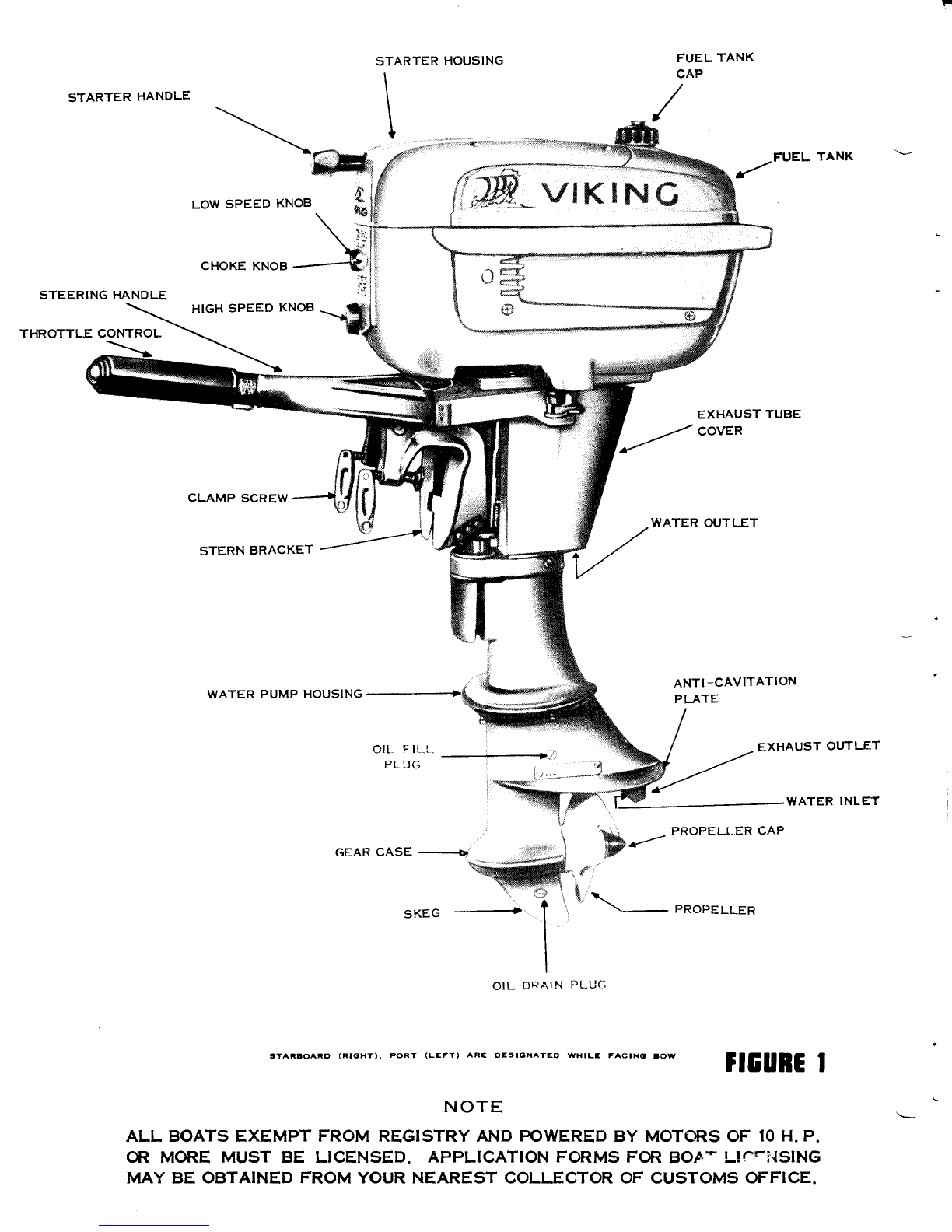
Figure 1 for locations
of cooling system parts.)
NOTE
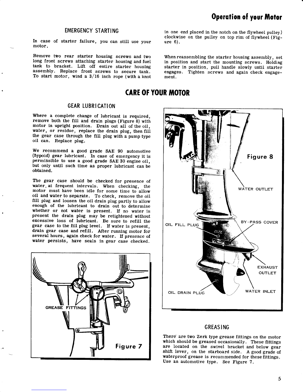
I1, while operating motor at full speed, it
should show signs of slowingdown, immedi-
ately check water drscharge at water outlet
(Figure B) located at rear of the motor di-
rectly below cylinder. In case no watei is
being discharged, immediately shut off the
motor and check water inlet (Figure 8) for
obstruction. If no obstruction is found, it
may indicate worn pump parts.
REMOVING
MOTOR
FROMBOAT
At end of run, with motor running in NEUTRAL,
plose fuel shut-off valve and permit motor torununtil
it stops, draining carburetor. Close air vent screw
in filler cap. The motor can then be carried with-
out fuel leakage. For safety, always drain fuel
tank before transporting motor. Also drain water
thoroughly as in "Care of Motor in CoId Weather. "
When removing motor from boat, Iift motor in a
straight upward position and hold this position for
a brlef period until aII water is drained from the
underwater exhaust tube and water cooling system.
Do not stand motor on top or carry with the top down
before draining water, as this may allow water to
enter the power head from underwater exhaust tube.
CARE
OFMOTOR
INCOLD
WEATHER
The motor will not freeze while in use, but when it
is idle, water in the cylinders or pump might lreeze
and damage the motor. Drain by setting the motor in
an upright position and pulling starter cord several
times with speed control grip in STOP position. If
the motor is to be stored during cold weather, be
sure that no water is left in the motor or it mav
freeze. (See "Preparation for Storage. ")
SALT
WATER
INSTRUCTIONS
A little time spent in caring for your motor whenused
in salt water will aid in not only keeping it in good
running order but help in retaining its finish and ap-
pearance. Tilt the motor out of the water when it is
not in use. At the end of the day or when not using
the motor for a period of time it is advisable to re-
move it from the boat and to flush it by running it in
a tank of fresh water. Wipe the motor dry and go
over all parts with an oily cloth. This should be
done as soon as possible after removing the motor
from the boat.
PREPARATION
FOR
STORAGE
No outboard motor should
be placed
in storage
with-
out considering
the necessaryprecautions. U motor
Coreol
yourlulolor
is operated in salt watet, flush by running in a tank
of fresh water. Drain and refill gear case with the
proper lubricant. See page 5.
Prior to storing the motor, run it for about one-half
(172) minute in choke position. Shut off motor with-
out pushing choke back to normal position. Purpose
of this operation is to flood the inner parts of tlie
powerhead with oil (oil in fuel mixture) while in
storage.
Drain all water from the cooling system. See "Care
of Motor in CoId Weather. "
Drain all fuel from fuel tank, gas.line and carbure-
tor.
Under no circumstances should the motor be stored
in an inverted position. It should be hung on a rack
similar to the manner in which it is mounted on the
boat. Store in a dry place. Wrap the motor in a
piece of canvas, old blanket. or heavy paper.
PUTTINGMOTOR
INUSEAFTERSTORAGI
Pull off spark plug Ieads and remove spark plugs.
If rubber spark plug hoods have been removed from
ignition leads, be sure to ground Ieads to some part
of motor to prevent possibility of spark. (THIS IS
IMPORTANT. ) Spin motor by pulling on starter cord
to remove excess oil from cylinders. Clean spark
plugs, check gap and replace. InstaII new plugs if
they are cracked, broken, or badly burned. Tighten
a-llscrews and nuts. Check adjustments such as tilt-
ing friction, co-pilot, and carburetor knob.
RUNNING
MOTOR
IN
TESTTANK
1. Do not run motor out of water.
2. Do not "break-in" motor in tank.
3. Remove water by-pass cover (small metal strip
on lower port side of upper pump housing, Figure B).
4. When running in tank be sure gear housing and
propeller are submerged.
5. Do not race motor in tank.
6. Use test propeller when testing motor in tank.
7. Cavitation (air pocket around propeller) may occur
when operating motor in tank with regular propeller.
Motor will then not perform properly or it may race
and be damaged as a result.
MOTORSTHAT
HAVI
BEIN
SUBMERGED
Precaution should be taken to prevent a motor going
overboard (see page 1). However, if a motor has
been submerged, it should be recovered as quickly
as possible.
Since the motor is temporarily out of working order,
do not attempt to operate it untii the following pro-
cedure has been used to restore it to service.

Co'eof
yourflolor
1. Drain fuel tank by removing fuel tank filler cap
and turning motor upslde down.
2. Removeplug at very bottomofcarburetor (item 52,
Page 12) thereby draining watCr and fuel from car-
buretor. Pour enoughfresh fuel into gas tank to re-
move any rqlter from fuel line, by permitting fuel to
run out of carburetor drain plug hole (fuel tank shut-
off valve should be open). Whenall traces of water
are removed, replace plug.
3. Remove and dry spark plugs. If rubber spark
plug hoods have been removed, be sure to ground
wires somewhere on motor. . Lay motor dorpn on
gear shlft handle slde and crank motor. Turn motor
so that spark plug holes are down and again crank
motor until no further water is expelled.
4. Check spark by inserting screw or other small
metal object tnto rubber spark plug hood to rnake
contact with terminal sprlng in hood and holding
screw about 1/4 lnch from cylinder and cranking
motor rapidly. Check spark from both leadwires.
If rubber hoods are not on leadwires, be sure to
ground one lead while checking the other.
5. Replace all parts removed, fill tank with new fuel
mixture, and start motor. It may be necessary to
clean water from points of spark plugs several times
as there ls a possibility of small drops of water re-
maining ln the cylinder,which may short the plugs.
The abovelnstructions are primarily for motors that
have been submerged in fresh water. For motors
submergedin salt water a few additional precautlons,
listed below, E&y be necessary.
1. Remove carburetor and fuel tank, andwash with
fresh water. Dry thoroughly.
I BREAKER ARM
2 BREAKER POINTS
3 BREAKER ADJUSTING SCREW
4 CONDENSER
5 BREAKER BASE SCREW
6 COIL AND LAMINATION
ASSEMBLY
7 BREAKER CAM
8 FELT OILER
9 CRANKSHAFT
2. Remove flywheel, and wash magneto with fresh
water.
3. It is advisable to wash external working parts,
such as the starter 'mechanism, with fresh water
and lubricate. Internal working parts are lubricated
by the fuel mixture.
If motor will not operate after the aboveinstructions
have been followed, disassemble and wipe aII parts
dry. Coatwith oil to prevent rust andfollow instruc-
tions under "How to Obtain Service. " (See back
cover.
)
MAGNEIO
It may be necessary occasionally to inspect the
magneto. If so, it is necessary to remove the gas
tank andflywheel. However, i-fcleaning or adjusting
of points is required, remove the starter hous-
ing, (see
page
5, "EmergencyStarting") andthethree
screws releasing the starter ratchet and flywheel
cover. Access
to the points
for cleaningor adjusting
is possible through the opening on the top of the
flywheel. HOWTOREMOVEFLYWHEEL
Disconnect fuel line and remove fuel tank. Use fly-
wheel puller if available. If not, hold flywheel rigid
and unscrew the flywheel nut about two full turns.
Have someone liJt up on the flywheel and then place
a piece of bar solder or a block of Iead over the fly-
wheel nut and tap a sharp blow with a hammer. If
flywheel does not come off , Ioosen nut a trifle more
and repeat procedure.
When flywheel comes off , use care not to Iose key by
which flywheel is held inengagementwithshaft. When
FigurelO

Core
ofyour
filotor
CHECKING BREAKER POINT GAP ADJUSTING BREAKER POINT GAP
Figure
ll
again replaclng flywheel, be sure key is in plate and
f.its snugly, then draw up nut as tight as possible.
IMPORTANT: Tapers onflywheel and
crankshalt must
be perfectly clean and dry before reassembling.
MAGNETO
LUBRICATION
The magnetois equipped
with a felt oiler to lubricate
the cbm and reduce wear on.the cam block of the
breaker (Figure 10). A few drops of light oil should
be put on the felt once or twice a year.
CLEANAND
ADJUST
BREAKER
POINTS
After removing starter ratchet and ftywheel cover,
revolve flywheel until opening is directly over
breaker (there are two breakers on this magneto).
Carefully spread points with small screwdriver.
1 LOW SPEED KNOB
2 LOW SPEED NEEDLE
3 PACKING NUT
4 CAM FOLLOWER LEVER
5 THROTTLE CAM FOLLOWER
6 CARBURETOR BODY
7 THROTTLE SHAFT
8 FLOAT BOWL
9 HIGH SPEED NEEDLE
IO HIGH SPEEO KNOts
II CHOKE SHAFT
12 CHOKE KNOB
Insert pointdresser. (Sandpaper,
fine coil file, nail
file, etc. NEVER USEEMERY CLOTH.) Release
points, work dresser up anddownto smooth. Follow
same procedure with piece of thick smooth paper to
remove traces of foreign particles which might be
left on points.
AJter cleaning, reset point gap to .020 inch maxi-
mum opening as follows: When hole in flywheel is
directly over the breaker, maximum opening of the
breaker is obtained. Check with .020 inch feeler
g?ge. If openingis under or over .020 inch loosen
breaker base screw (item 5, Figure 10) slightly.
Turn adjusting screw (item 3, Figure 10)to right or
left until required setting is obtained. Tighten
breaker plete screw and re-check with gage. See
figure 11.
9
Figurel2

(ore
ol
your
lholor
CARBURETOR
AIRSILENCER
The air silencer does not function as a filter, there-
fore it is never necessary to remove it for cleaning
purposes under normal use. Its only function is for
quiet motor operation.
CARBURETOR
ADJUSTING
NEEDLES
Should the adjusting needles become so Ioose that
the knobs will not remain in a set position, they
can usually be tightened by drawing down on the
packing
nuts (item 3, Figure 12).
NOTE
Turn carburetor knobs counterclockwise1,/2
turn before tightening
packing
nutsto prevent
damageto needle seats.
If tightening of the packing nut will not help, it may
benecessarytoreplacethepacking.
Toreplacepack-
ing remove the air silencer, needles, packing
nuts,
washers, and ALL of the old packing. Install new
packing and reassemble.
e/t"tA e/4arrf
This chart will provide an outline for systematic tracing of operating difficulties.
The cruses Iisted are those which the average oMer can locnte with IittIe diffi-
culty. Once you have located the cause, the remedy is usurlly selJ-evldent.
If faulty motor operation cannot be trac€d to any of the causes hsted' we re_
commrnd that you see your dealer.
Always nrake sure that you have been usin€i the correct gasoline-oil mixture,
and are followrng operatinja instructlons accurately.
Spark plugs are one of the most common sources of trouble. It may save con-
siderable time if spark plugs, then the other ignition parts, are checked first.
MOTOR WILL NOT START
FUEL TROUBLE
Tank empty
Shut-off valve closed.
Filler cap vent closed.
Water in carburetor, tank or strainer.
Carburetor nozzle or passages clogged.
Strainer screen between shut-olf valve and gas
tank clogged.
Fuel Iine clogged.
Improper fuel and oil mixture.
NO SPARK TO PLUC
Lead to spark plug disconnected or grounded.
Breaker points not set at .020 inch gap.
Brealer points corroded.
Loose or broken wtre in magneto.
NO COMPRESSION
Leaking gasket or stuck reed vrlve.
SPARK PLUG TROUBLE
Fou
I
ed.
Porcelain cracked.
Center electrode (Pole) Ioose.
Pornts not set at .030 inch gap.
MOTOR KNOCKS
Flywheel hub loose.
Flywheel nut loose.
Incorrect spark plug pre-igniting.
MOTOR IS STIFF AND CRANKS HARD
MOTOR WILL NOT IDLE
Carburetor not adjusted properly.
Improper gasoline and oil mixture.
Throttle stuck op€n.
Dirty or defective spark plug.
Clogged carburetor.
lmproperly set breaker Points.
MOTOR MISSES
wlRINC
Loose or broken ignition ure.
Bruken ur orl-soaled insulation on wire.
MAGNETO
Weu or broken brealer pulnl spring.
Corroded or dirty breaker Points.
Breaker points not set at .020 inch.
CARBURETOR
Nozzle or feed hole dirty.
Water or foreign matter in strarner.
Carburetoi passages clogged.
MOTOR LOSES POWER
INCORRECT FUEL MLKTURE
Too rich - motor slows dom and Iour cycles (fires
every other compression stroke).
Too lean - motor slows dom and may back fire.
MOTOR VIBRATES
Faulty ignition or carburetion.
Loose pivot bearing.
Bent or broken propeller blade or motor loose on
boat.
MOTOR RUNS BUT BOAT MAKES LITTLE OR NO
PROCRESS
Badly bent propeller blades.
Weeds or rope wound around propeller.
Rope or other obstruction dragging in mter.
l0
Clogged water pump inlel deep enough in water

AUXII.IARYEQUIPMENT,
ACCESSORIES
AVAILABLE
FORYOUR
MOTOR
The Ull0llc Auxiliary
FueI
System,
now available for your 5 horse-
power outboard motor, will Uiveyou
extra hours of outboarding without
refueling. The system includes the
tank, pump, hoses and all necessary
fittings. All required drilling and
cutting has been incorporated in thc
motor and the fuel system can be
attached easily in a few minutes
time.
A special kit can be purchased from your dealer
to modify your 5 horsepower outboard motor
for remote control . With this kit, it is pos-
sible to attach or detach the new UllfillG n"-
mote Control System in a few minutes time.
The control box can be placed on either side
of the boat. One lever controls the gearshift,
the other the throttle. Cables are rriade in a
variety of lengths to suit any steering position.
ll
FOR FURTHER INFORMATION, ASK THE DEALER. FROM WHOM YOU OBTAINED THE MOTOR

Repoir
Ports
Lisf
CARBURTTOR
#
I
l5
r*
tI
13 ,L
l0
o
\II
l9
e
2l
9\ \20
%0
I
I
8
/ n,' )z
2'd4 I t
*sJ

RepoirPorlslist CARBURTTOR
Ref
No. Part
No. Description Ref
No, Part
No. Description
1
2
3
4
2L
22
23
24
25
26
27
28
29
30
31
5
6
dI
8
I
10
11
L2
13
l4
15
16
L7
18
19
20
552203
552204
55151
7
5912?9
591482
303479
203355
133451
552622
552623
85-64
7L-t487
301858
552608
552614
552609
43-259
200931
203652
302L24
552615
591569
19-136
30343?
5915?0
85-101
591545
303492
203166
?1-
1052
71-1038
552605
Screw- ChokeKnob.
Knob - ChokeControl
Screw - Carburetor Control
Knob
SlowSpeedControl Knob and
StopPin Assembly
High Speed
Control Knob and
StopPin Assembly
Nut- Slow
SpeedNeedleValve
Washer - Carb. SlowSpeed
Valve Nut
Screw- Manifold to Crankcase
Gasket - Manifold to LeaJ Plate
Gasket - Leaf Plate to
Crankcase
Nut- Leaf to Leaf Plate Screw
Washer - Lock, LeaJto Leaf
Plate Screw
Screw - Leaf Attaching
Stop- Leaf
Leaf
Plate - Leaf .
Screw - Silencer to ManiJold
Screw - Silencer to Carburetor
Plug - Button, Air Silencer
Screw - Cover Plate to
Sllencer Body
Plate - Air SilencerCover . . .
Loading Tube andAir Silencer
Body Assembly.
Nut - Carburetor to Manifold .
Gasket - Carburetor to
Mani-fold
Intake Manifold and StudAssy.
. Stud- Carburetor to ManiJold
Carburetor Assembly Complete
. Nipple - Gas Line
. Spring - Cam Follower
. Clip - Cam Follower
. Screw - Cam Follower
. Follower - Throtile Cam .
32
33
34
35
36
37
38
39
40
4l
42
43
44
45
46
47
48
49
50
51
59
60
61
62
63
64
65
52
53
54
55
56
JJ
58
203163
41-
110
203164
302430
302977
21-I63
30299?
303448
43-L23
300179
3034?6
43-123
7l
-1
589
302994
300096
375919
3?5918
301996
30344?
302984
303041
552606
303?60
303444
375921
?1
-103
I
3029?8
303049
303048
302996
303?60
375922
3?6531
304326
Lever - Cam Follower
Pin - Cam Follower Link.
Link - Lever to Follower. .
Screw - Spring to Carburetor
BodY .
Spring - Choke Contiol Rod
Cotter Pin - Choke Control Rod
Rod - Choke Control
Needle Valve - Slow Speed
Packing - Slow Speed Yalve
Nut - High Speed Needle Valve
Needle Valve - High Speed
Packing - High Speed Valve
Screw - Float Chamber to
Carburetor Body
Gasket - Float Chamber to
Carburetor Body.
Hinge Pin - Float Arm . . .
Float and Float Arm Assembly
Float Valve and Seat Assembly
Washer - Float Valve Seat
Nozzle - High Speed
Gasket - Float Chamber to
Carburetor Body Boss
Screw - Float Chamber Drain
Float Chamber
Screw - Choke Valve
Choke Valve
Choke Shaft and Lever Assy. .
Screw - Throttle and Cam
Follower Lever
Lever - Cam Follower to
ThrotUe Shaft
Cotter Pin - Throttle ShaJt .
Washer - Throttle Shaft
Spring - ThrotUe Shaft .
Screw - Throttle Valve . .
Throttle ShaJt& Lever Assy
Carburetor Body - Plug and
Throttle Valve Assembly
. Throttle Valve
t3

RepoirPorts
Iist
POWTR
HEAD
9
I
@r
3r_--_n
/zN lY
f_,Rb /
}{rq
l(
408
-+r
32 1
36
\
@
,(m
I
37
Ir
,_8,.(
%--
/\
14
=9a'
t/
l./
l/
t3
l0
\
p

RepcirPortslist POWTRHTAD
1
2
3
4
5
6.
7
8
I
10
11
l2
13
13
L4
15
16
17
18
19
20
2l
00646
L32123
03109
552611
132346
300154
300455
300454
25-74
30340?
803439
200322
376290
25-74
552624
552625
4L-223
3032?8
30327?
302431
41-178
Screw- Cyl. Cover to Fuel Tank
Screw- Brg. Clamp and
Exh. Cover.
Screw - Bearing Clamp
Clamp - Bearlng
Lever - Armature Plate Control
Screw - Anchor and Exhaust
Cover to Cyllnder
Washer - Anchor and Exhaust
Cover Screw
Anchor - Ignition Leads
Grommet - Ignition Leads
Screw - Exh. Cover to Cyllnder
Cover - Exhaust
Gasket - Exhaust Cover
Spark Plug (Champton
J6J) . . .
SparkPlug (Auto-Lite ASX). . .
Screw- Cover to Cylinder .
Cover - Cylinder
Gasket
- Cylinder Cover
Screw - SupportPlate
Support
- Armature Plate
Ring - Arm. Plate Retaining
Screw- Cylinder to
Crankcase, Upper
Screw- Cyllnder to Crenkcase,
Lower
22
23
24
25
26
27
28
29
30
31
32
33
34
35
36
37
38
39
40
41
42
43
L-47
552613
19-19r
03248
203235
5915?9
27-77
303649
120395
120110
303333
41-
333
3?6067
591542
4t-44
4L-L7
5526
8l
Washer - Cylinder to
Crankcase Screw
Screw - Cylinder to Crankcase .
Pln - Taper, Cyllnder to
Crankcase
Screw- Fuel PumpOutlgt PIug.
Clamp - Oil Return Hose . . . .
Hose - OiI Return
Nipple - Oil Hose
to Cylinder. .
Screw- LeaJValve to Crankcase
Plate - Leaf Valve
Valve - Leaf, Crankcase Draln.
Cyllnder & CrankcabeAssembly
. Screw - Cyllnder to Crank-
- 'case, Center
Slinger - Oil .
Key - Crankshaft .
Ring - Lock, Plston Pln
Ptn - Wrist
Ring - Plston
Piston & Dowel Pin Assembly .
Connectlng
Rod and Lockplate
Assembly
. Screw - ConnectingRod
. Lockplate - ConnectlngRod
Crankshaft
l5

fiIFUIIOI.D
&ERACKET RepoirPorts[ist
J-
43
\- \-
30=..--45--t-lJ
fl=R( v
'[ffi:
'(P=;;
NW
lllu
.q'r.
'*_-37
,W
$
t/
///
*\
N)\
l6

Repoir
PortsIisl TIA}IITO1D&BRACKTI
Ref .
No. Part
No. Description Ref.
No. Part
No. Description
I
2
3
4
5
6
I
8
I
10
11
t2
13
L4
15
16
t7
18
19
20
2l
22
23
24
25
26
27
28
29
30
31
32
33
34
35
36
37
38
39
40
4l
42
43
44
45
46
47
48
49
50
51
52
53
54
55
56
302?10
301656
303282
552209
203260
133452
3030?8
303093
300346
303252
3021t7
3027L2
376691
316042
303096
30s0?9
71-135:
3?6689
303142
30310?
303800
303140
5t-47
303467
303589
303588
30358?
303585
303586
303714
303?15
15
-268
304254
303?75
303864
303191
303236
552457
552499
552498
271
626
591
583
85-64
303701
303702
30339?
303392
303394
303369
303461
303458
303465
303393
3026?7
3033?2
303362
Screw - Steering HandleGrip
Spring - Grip to Friction Block
Block - Grip Friction. .
Grip - Steering Handle
Plate - Throttle Control
Screw - Steering HandleHalves
Handle - Steering, Inner HaIf.
Pin - Groove, Gear and Shaft
Assembly
Washer - Steering Handleto
Spring
Bushing - Steering Handle
Washer - Steering Handle
Throttle Control Gear and
ShaftAssembly, Long
Handle - Steering, Orter Half
Cover - Steering Handle Gears
Washer - Steering Bracket to
Handle
Screw - Pinion
Gear andShaftAssembly, Short
Pinion - Throttle Control.
Washer - Pinion Gear
Gear - Throttle Control
Bushing- Throttle Control.
Screw - Exh. Tubeto Cylinder.
Gasket - Exh. Tube to Cylinder
Screw
- Exh.Tube
Cover,Upper
Screw
- Exh.Tube
Cover,Center
Screw
-Exh. Tube Cover,
Lower
Cover - Exhaust Tube
Gasket - Exhaust Tube Cover.
Screw - Shift Lever Shaft
Assembly
Washer - Shift Lever to Shaft
Pin - Cotter,Shift
Rod
Lever - Shaftto Shift Rod
Washer - Shift Lever andShaft
Assembly,Inner.
Washer - Shift Lever andShaft.
"O" Ring - Shift Lever
Spring - Washer
Pin - Straight, Shift Handle.
Washer - Shift Handle Pivot Pin
Spring - Shift Handle
Shift Handleand Pin Assembly.
Shift Shaftand Arm Assembly
Nut - Shift Rodto Connector .
Washer - Lock, Shift Rod Nut
Connector - Shift Rodto Lever.
Screw - Friction Band
Band- Friction
Screw - SpringRetainer
Retainer - Upper Mount Spring.
Spring - Lower Mount
Spring - Upper Mount
Spring- Reverse Lock Rod
to
Reverse Rod
Screw.- Steering
Bracket to
Retainer,Upper
Screw - Steering
Bracket to
Retainer, Lower.
Retainer - Steering
Bracket
Sleeve
- Friction Band.
63
64
65
66
6?
68
69
?0
7l
72
?3
74
tc
76
tl
78
?9
80
81
5?
58
59
60
61
62
85
82
83
84
86
87
88
89
92
93
94
95
96
90
91
97
98
99
100
101
304131
303371
303359
303696
3033?0
30369?
303363
1326?9
5511l3
303464
303049
304130
304129
1?
-1
82
25-196
302051
303349
303396
2026L7
160084
301983
20202L
376395
376082
375744
302420
41
-48
3?6081
303398
303500
376269
303353
303350
550565
303364
85
-64
303706
303?05
303408
303368
303409
303348
?-261
3?6459
3?60?I
Bracket - Swi'rel
Absorber - Shock,
Lower
Swivel Bracket
Washer - Thrust, Steering
Bracket to Swivel Bracket
Pin - Swivel Bracket, to Upper
Liner
Liner - Upper
Spacer- Co-pilot Plate to Upper
Liner.
Plate - Co-pilot
Screw - Co-pilot Plate
Spring - Co-pilot Plate Screw
Spring - Reverse Lock Rodto
Swlvel Bracket
Pin - Cotter, ReverseLock
Shaft.
Rod - Reverse Lock
Lever - ReverseLocking
Nut - Tilting Bolt
Washer - Tilting Bolt.
Spring - Tilting Bolt
Bolt - Tilting
Screw - SternBracket. Port to
Starboard
Shim - Stern Bracket to Swivel
Bracket
Ball - Stern Bracket to Swivel
Bracket
Washer - Conical
Spring - Tilting Lever
Tilting Lever Assembly.
SternBracket Assembly,
Starboard
. ClampScrew,Plate and
RetainerAssembly
. Retainer - SwivelPlate.
. Plate - ClampScrewSwivel
Stern
BracketAssy.,Port (Also
Includes
Items 81,82and83).
Screw - SteeriirgBracket to
Pilot Shaft
Shaft- SteeringBracket Pilot
Steering Bracket and Bushing
Assembly
Plate - SteeringBracket
Support - Drive Shaft Casing to
Steering
Bracket
Pin - Cotter, Reverse Lock Link
to Lever
Grommet - Reverse Lock Arm
to ReverseLock Link
Nut - Lock, ReverseLock Pin
Coupling
Coupling
- ReverseLock Link
Link - ReverseLock, Lower .
r.ink - ReverseLock, Upper
Screw - Shoulder,
Reverse
Lock Arm
Arm - ReverseLock
Nut - Water Tube .
Gland- Water Tube.
Water TubeAssembly.
Driveshaft Casing,
Exhaust
TubeandCore.PIu; Ass; :bly
t7

Repoir
Ports
list
€D_r
@--z
6r=-=_--a
@-;
.( E--5
IleA
lnl ad---.-- ^r
w-' L:' )f /1
,^ v lt-41
llrtl I l-
fm\_,,
wr'
o
@--ae
GEAR
CASE
,'51
e'_-52
e'
:38s.
.._L,,
tt
3'Ifl
\
Nj, l,,i
r;'Ttr@re
it\A;
\w'M
2s
)o(4\A-,, ,|),
9
(
Table of contents
Other Eaton Outboard Motor manuals
Popular Outboard Motor manuals by other brands

Mercury
Mercury Marathon - 30 Operation and maintenance manual

Watersnake
Watersnake Shadow MK II SWNG 44/48 owner's manual

Yamaha
Yamaha F80A owner's manual

Outboards Group
Outboards Group 2.2A owner's manual

SLEIPNER MOTOR AS
SLEIPNER MOTOR AS SIDE-POWER SEP IP - 170 instruction manual

Vetus
Vetus BOW4512D Operation manual and installation instructions