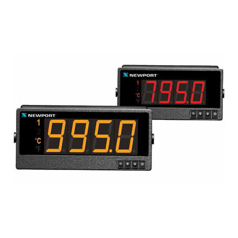
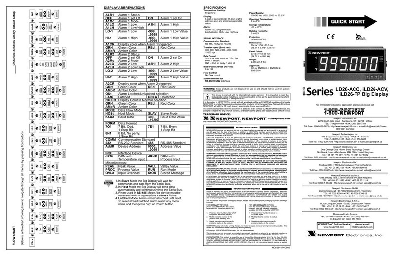
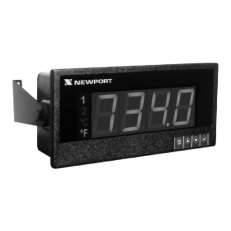
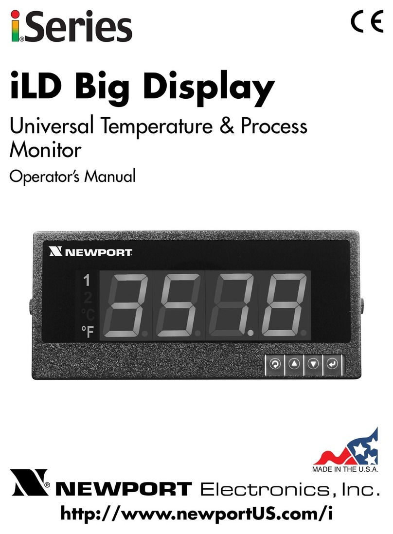
Newport 6155AS User manual

6155AS
6 DIGIT SERIAL INPUT
REMOTE DISPLAY TYPE

TABLE OF CONTENTS
SECTION TITLE PAGE
1.0 GENERAL INFORMATION 1
2.0 GETTING STARTED 3
2.1 Unpacking and Inspection. 3
2.2 Safety Considerations 3
2.3 Turning It On 4
2.4 Message display at Power-up 4
3.0 OPERATION 5
3.1 Introduction 5
3.2 Message Format 5
3.3 Example Message 6
3.4 Addressing 7
3.5 Protocol 7
3.6 LH/RH LED Indicators 7
4.0 CONFIGURATION/MECHANICAL INSTALLATION 8
4.1 AC Power Selection Jumpers 8
4.2 Module Address 8
4.3 Baud Rate 9
4.4 Mode 9
4.5 Input Type Selection 10
4.6 Power and Signal Connections 10
4.7 Input Signal Inversion 11
4.8 Interfacing the 6155AS with Newport 269/P6000 12
4.9 Interfacing the 6155AS with IBM PC Compatibles 13
5.0 SPECIFICATIONS 14
5.1 General 14
5.2 Communication 16
5.3 Power 16
5.4 Display 16
5.5 Dimensions 16
5.6 Operating Environment 16
6.0 MAIN BOARD DRAWINGS. 17
Rev Eco. No Date By CHK
E U0092 8 Aug 90 RS

ILLUSTRATIONS
FIGURE PAGE
1-1
The 6155AS Block Diagram
2
3-1
Display Character Table
5
3-2
Control Characters
6
4-1
Jumper Locations On Power Transformer
8
4-2
DIP Switches
8
4-3
6155AS Rear Panel With Pin Assignments
10
4-4
6155AS/269 Interfacing
12
4-5
6155AS/P6000 Interfacing
12
4-6
6155AS/IBM PC Interfacing
13
6-1
Case Dimensions
17
6-2
Main Board
&
Display Board Assembly Diagrams
18
6-3
Main Board Schematic
19
6-4
Display Board Schematic
20
6-5
Power supply Assembly Diagram
21
6-6
Power Supply Schematic
22
6-7
DC Power Supply Schematic (Option)
23
6-8
DC Power Supply Assembly (Option)
24
6-9
Exploded View Of Module
25

1 U02124ML-01-UK
SECTION 1
GENERAL INFORMATION
The 6155AS is a six digit remote display module. It accepts serial ASCII
coded data into a differential or single ended line receiver, at common Baud
rates.
Numeric data and a selection of other characters can be displayed. The
character set includes decimal point and negative sign. Simple messages
e.g.
Hi ALL
o
C
o
F
can be formed with characters presentable on
seven segment displays.
Multiple serial data may be transferred by sending code 03 followed by 02, an
address from 0 to 15 ( ASCII 30 to 3F) and the data. The address 0 (ASCII
30) is common to all remote displays for simultaneous display of the same
message.
The 6155AS may be set-up to operate in a 'strobed' mode whereby the data
string is transferred to the display on reception of a carriage return.
Alternatively a 'shift' mode can be used in which the characters are displayed
according to their current position in the input shift register. Two further modes
enable connection to the Newport 269 and P6000 panel meters for 'remote
display purposes.

2 U02124ML-01-UK
Figure 1-1 The 6155AS Block Diagram

3 U02124ML-01-UK
SECTION 2
GETTING STARTED
2.1 UNPACKING AND INSPECTION
Your 6155AS remote display was systematically inspected and tested, then
carefully packed before shipment. Unpack the instrument and inspect for
shipping damage. If damage exists, do not attempt to operate the unit. Notify
the freight carrier immediately.
2.2 SAFETY CONSIDERATIONS
As delivered from the factory/distributor, this instrument complies with
required safety regulations. To prevent electrical or fire hazard and ensure
safe operation, please follow the guidelines below:-
POWER VOLTAGE -
Verify that the instrument is connected for the power
voltage rating that will be used. If not, make the required changes as
indicated in section 4.1 of this manual. This instrument is delivered with A.C.
power connection for 230V in Europe and for 115V in the USA as standard
(unless the instrument is fitted with DC drive capability). Verify that the
instrument is configured for the power voltage rating that will be used (See
Section 4.1).
POWER WIRING -
This instrument has no power on switch; it will be in
operation as soon as the power is connected.
Verify that the power cable has the proper ground (earth) wire and that this
wire is properly connected to a ground (earth) point. If the panel cut-out is a
metal enclosure, it must be grounded (earthed).
This instrument is protected according to the class I of the IEC (International
Electrotechnical Commission) 348 and VDE 0411 regulations.
RAIN OR MOISTURE -
Do not expose the instrument to condensing moisture.
FUMES AND GASES -
Do not operate the instrument in the presence of
flammable gases or fumes; such an environment constitutes a definite
safety hazard.
EXERCISE CAUTION -
As with any electronic instrument, high voltage may
exist when attempting to install, calibrate, or remove parts of the instrument.

4 U02124ML-01-UK
2.3 TURNING IT ON
Connect the proper line voltage to the power screw terminal (TB1).
See Figure 4.3.
WARNING:
INCORRECT POWER CAN DAMAGE YOUR 6155AS MODULE
2.4 MESSAGE DISPLAY AT POWER UP
At initial Power-up the 6155AS displays a message which indicates the
following configuration details:-
i) PROGRAM REVISION CODE
i) SELECTED MODE (0, 1, 2 or 3)
ii) PRESENT INPUT LEVEL ( ⎯= HIGH, = LOW)
iii) SELECTED ADDRESS (0 to 15)
iv) SELECTED BAUD RATE (0=300,1 =1200,2=2400,3=9600)
i.e. The following display "AO_?I " would indicate
PROGRAM REVISION CODE A;
MODE 0 INPUT LINE LOW;
ADDRESS 15; and 1200 BAUD RATE Selected.

5 U02124ML-01-UK
SECTION 3
OPERATION
3.1 INTRODUCTION
This section provides information regarding transmission of messages to the
module. See section 4 for configuration of jumpers, links and DIP switches.
3.2 MESSAGE FORMAT
All messages transmitted to the module should be in ASCII. The valid
characters are shown in the diagram below
30 0 3C
c 48
H 54
T
31 1 3D
= 49
I 55
U
32 2 3E 4A
J 56
V
33 3 3F
? 4B
+ 57
34 4 40
(Space) 4C
L 58
/
35 5 41
A 4D 59
Y
36 6 42
b 4E
N 5A
Z
37 7 43
C 4F
o 5B
o
38 8 44
d 50
P 5C
\
39 9 45
E 51
Q 5D
3A -46
F 52
R 5E
N
3B _47 53
S 5F
,
Figure 3-1 Display Character Table

6 U02124ML-01-UK
Various control characters are also used :-
ASCII
CODE ACTION
03 ETX : Stops the module receiving further data except code 02
13 XOFF: As per ETX
02 STX : Starts the module receiving data. If the instrument has an
address other than '0' the next character must be the address
of the instrument or it will return to an inactive state
11 XON : As per STX
0D END OF DATA: In shift mode next valid data will clear the
display and insert character into least significant position. In
strobed mode, the message is transferred to the display.
20 Inserts a space
2D Inserts a negative sign (-)
2E Adds a decimal point to the last character entered
0C Blank Display
1B Resets to Power-up condition
Figure 3-2 Control Characters
All other characters are invalid and will be ignored.
3.3 EXAMPLE MESSAGE
An example would be to write the message "Lo -1.5" to module set at
address
04.
This message would be sent as follows :-
(This assumes the display to be in the inactive state i.e. having previously
received a 03 or 13 code or else in the powered-up condition).
02 Activate module
34 Module address
4C
L
4F O
20 Space
2D Negative sign
31 1
2E Adds decimal point
35 5
0D Transfer data to display (only needed in strobed mode)
03 Disable module

7 U02124ML-01-UK
3.4 ADDRESSING
There are 16 possible addresses, 0 to 15. These correspond to addresses
set up on the DIP switches (see section 4.2) the 0 address (ASCII 30) is a
common address and any characters following are displayed by all units.
3.5 PROTOCOL
The following serial ASCII protocols are switch selectable:
MODE 0: All data received is displayed (except illegal characters) in the
order in which they are received.
MODE 1: The last six characters received are displayed once a carriage
return character (OD) is received.
MODE 2: 269 Temperature Meter Display - display is updated when a
carriage return character is received. When the transmitting meter is
measuring temperatures this remote module repeats the four characters
shown on the 269, followed by degrees C or degrees F. When the
transmitting 269 is indicating millivolts, this remote module repeats the four
characters in the middle four positions, and negative indication is in the left'
hand position. Overload indication is all E's (See section 4.7 for interfacing
details).
MODE 3: P6000 Universal Counter (without units of measurement) Display
is updated when the carriage return character is received. The display
repeats the six characters shown on the P6000. If the first character
received is a H the upper left hand indicator will light, if a L is received the
lower left hand indicator will light and if the first character is a B, both
indicators will light (See section 4.7 for interfacing details).
N.B. The P6000 must be configured to transmit a 9 character message, not
a 12 character message.
3.6 LH/RH LED INDICATORS
Two rectangular LED's are provided on the 6155AS for use as general
indicators
I
alarm condition displays. An extra (seventh - MSD) character
transmitted (in modes 0 or 1) will control these two LED's as follows:-
RH LED
=
Upper horizontal segment
=
segment A
LH LED
=
Centre horizontal segment
=
segment G
Thus any valid character (see figure 3.1) can be sent which includes neither
I either or both of the above segments to operate the indicators as required.

8 U02124ML-01-UK
SECTION 4
CONFIGURATION/MECHANICAL INSTALLATION
4.1 AC POWER SELECTION JUMPERS
For 230V AC operation, link W1 should be installed (Remove links W2 and
W3 if fitted). For 115V AC operation, links W2 and W3 should be installed
(Remove link W1 if fitted).
Figure 4-1 Jumper on Power Transformer
AC POWER CONNECTIONS
WIRE COLOUR
AC POWER EUROPE USA
AC POWER HI BROWN BLACK
AC POWER LO BLUE WHITE
AC POWER GBD GREE/YELLOW GREEN
4.2 MODULE ADDRESS
To set module address, baud rate and mode the front lens of the module must
be carefully removed with a thin bladed screwdriver, to gain access to the DIP
switches (Figure 4-2)
Figure 4-2 DIP Switches
Note
For DIP switches 1-8
UP = 0
DOWN = 1

9 U02124ML-01-UK
Switches 1 to 4 are used to set the module, address, the following table lists
all possible combinations.
S1 S2 S3 S4 ADDRESS DISPLAY ASCII CHAR
0 0 0 0 0 0 0
1 0 0 0 1 1 1
0 1 0 0 2 2 2
1 1 0 0 3 3 3
0 0 1 0 4 4 4
1 0 1 0 5 5 5
0 1 1 0 6 6 6
1 1 1 0 7 7 7
0 0 0 1 8 8 8
1 0 0 1 9 9 9
0 1 0 1 10 -:
1 1 0 1 11 ,;
0 0 1 1 12 c<
1 0 1 1 13 ==
0 1 1 1 14 >
1 1 1 1 15 ??
4.3 BAUD RATE
Switches 5 and 6 set the baud rate.
S5 S6 BAUD
0 0 9600
1 0 2400
0 1 1200
1 1 300
4.4 MODE
Switches 7 and 8 set the mode.
S7 S8 MODE
0 0 0 (Shift)
1 0 1 (Strobed)
0 1 2 269
1 1 3 P6000

10 U02124ML-01-UK
4.5 INPUT TYPE SELECTION
Jumper settings for signal conditioning.
Type Jumpers TB2
HI LO
TTL B,C,G AIN COM
2mA Loop D,H,J,L BIN COM Loop powered
2mA Loop D,H,J,L AIN BIN RCRV powered
20mA Loop A,D,H,J,K,L BIN COM Loop powered
20mA Loop A,D,H,J,K,L AIN BIN RCVR powered
±5V D.F.H.I BIN COM
P6000 As above As above
±5V D,F,I BIN COM
Diff C,H BIN AIN Common at COM
Termination E
269 D,H,F,I AIN/BIN COM
4.6 POWER AND SIGNAL CONNECTIONS
Figure 4-3 6155AS Rear panel with pin assignments

11 U02124ML-01-UK
4.7 INPUT SIGNAL INVERSION
Solder switches SWI and SW2 and the main PCB assembly (U0092) allow
the input data logic polarity to be inverted. It is applicable both for external
powered and 6155AS powered 2/20mA current loops
i.e. 2/20mA = LOGIC 1 = SPACE
0mA = LOGIC 0 = MARK
Follow the procedure below to select this feature if required.
PROCEDURE.
The procedure for all other aspects of configuration remain unchanged.
1. Remove any connector(s) from the rear of the 6155AS
2. Remove the front panel lens
3. Remove the two size #8 case retaining screws from the rear of the
6155AS
4. The 6155AS meter can now slide forward out of its casing
5. Open-circuit solder-switch positions SWI-A and SW2-A
6. Short-circuit solder-switch positions SWI-B and SW2-B
7. Re-assemble the 6155AS meter now by reversing steps 1 to 4. above
Figure 1 Location of solder switches SW1 and SW2
Note.
The above configuration is only normally used for current loop operation. For
operation with other standard inputs (TTL, RS232, RS422, RS423 or
RS485) the solder switches SW1 and SW2 should be returned to the normal
configuration.

12 U02124ML-01-UK
4.8 INTERFACING THE 6155AS WITH NEWPORT 269/P6000 UNITS
Shown below in figures 4-4 and 4-5 are interconnection and configuration
details for using the 6155AS with Newport products 269 and P6000.
Figure 4-4 6155AS/269 Interfacing
Figure 4-5 6155AS/P6000 Interfacing

13 U02124ML-01-UK
4.9 INTERFACING THE 6155AS WITH IBM PC COMPATIBLES
Shown below in figure 4-6 are suggested inter-connection and configuration
details for using the 6155AS with an IBM PC
The IBM serial interface is first set-up and enabled by the following DOS
commands (See DOS manual for full details).
[MODE COM1: 300, N, 8, 2]
1 or 2
(I/FACE No jumper selected on PC Plug-in)
300 Baud
No Parity
8 Data bits
2 Stop bits
[MODE LPT1=COM1] Reroutes output to printer: LPT1 to Communications
adapter: COM1)
Any Data now sent to the printer LPT1 will now be displayed on the 6155AS.
i.e. If the following BASIC instruction is programmed:
[LPRINT "123456"] the 6155AS will display 123456.
Figure 4-6 6155AS / IBM PC Interfacing

14 U02124ML-01-UK
SECTION 5
SPECIFICATIONS
5.1 GENERAL
Function: A six-digit serial driven remote display module.
5.2 COMMUNICATION
BAUD RATE 300,1200,2400 OR 9600
MESSAGE FORMAT 1 Start Bit, 8 Data Bits or
1 Start Bit, 7 Data Bits and Parity
(Parity is ignored)
and 1, 1 1/2 or 2 Stop Bits.
HANDSHAKE No Handshake required, 6155AS
accepts data continuously.
DATA SENSE Idle low normal. Idle high set during
input type selection when required
(see Sec. 4.5)
SIGNAL INPUT 8 types of serial ASCII input can be
accommodated. (See Sec. 4.5 for
jumper selection.)
(1) TTL
LOGIC 1 =2V Min. =Space
LOGIC 0=0.8V Max. =Mark
LOGIC 0 Input current= -1 mA Max.
Vin Max. =15V
(2) 2mA LOOP (externally powered)
LOGIC 1 =1.5mA Min.=Mark
LOGIC 0=0.5mA Max.=Space
Volt drop. = 1 V Max.
Max input current.=0.5A
(3) 2mA LOOP (6155AS powered)
Open circuit voltage=5V ±5%
Compliance = 3.5V Min. Other
details as (2)

15 U02124ML-01-UK
(4) 20mA LOOP (externally powered)
LOGIC 1 =15mA Min.=Mark
LOGIC 0=5mA Max.=Space
Volt drop= 1 V Max.
(5) 20mA LOOP (6155AS powered)
Open circuit voltage=5V ±5%
Compliance = 3.5V Min.
Other details as (4)
(6) BIPOLAR ±5V (RS 423)
LOGIC 1 =3V Min. = Space
LOGIC O=OV Max.=Mark
OIC = Mark
Input Resistance=4 to 10Kohm.
Max input = ±7V
(7) BIPOLAR ±15V (RS 232)
LOGIC 1 =3V Min. =Space
LOGIC 0=-3V Max.=Mark
OIC = Mark
Input Resistance=4 to 7Kohm
Max input = ±30V
(8) DIFFERENTIAL (RS422/485)
Threshold= ±0.2V Max.
Hysteresis=50mV typ.
Input Resistance=12Kohm min.
Max. diff. input=±12V
Max.com.mode input= + 12/-7V
Termination = 120 ohm (selectable)

16 U02124ML-01-UK
5.3 POWER
AC Voltage: 120/240V (Selected by internal links see Section 4-1)
+10% -15%, 50-60Hz
Power Consumption 5 Watts (max)
DC Power (Option) Voltage: 9.5 to 32 V DC
Current: 800 mA (Max)
5.4 DISPLAY
Type: 7 segment red LED
Digit height: 14.2mm
5.5 DIMENSION
Case-size: Bezel 96x48mm
Depth behind bezel: 140mm
Panel cut-out: 92x45mm
Panel thickness: 0.8mm – 6.0mm
Weight: 500g
5.6 OPERATING ENVIRONMENT
Temperature: 0-50 °C
Humidity: 0-95% RH non-condensing

17 U02124ML-01-UK
Figure 6-1 Case dimensions
Table of contents
Other Newport Monitor manuals
Popular Monitor manuals by other brands

Asus
Asus VB171D - 17" LCD Monitor Service manual

EverFocus
EverFocus EN-7517E instruction manual

LG
LG 50PM1M - - 50" Plasma Panel Service manual
Smartec
Smartec STM-173 user manual

Siko
Siko MA501-S Additional to the Original Installation Instructions

Pioneer
Pioneer Elite PureVision PRO 1410HD operating instructions
