Newport 841-P-USB User manual

Virtual Optical
Power Meter
841-P-USB
User’s Manual


i
Warranty
Newport Corporation warrants that this product will be free from defects in
material and workmanship and will comply with Newport’s published
specifications at the time of sale for a period of one year from date of
shipment. If found to be defective during the warranty period, the product
will either be repaired or replaced at Newport's option.
To exercise this warranty, write or call your local Newport office or
representative, or contact Newport headquarters in Irvine, California. You
will be given prompt assistance and return instructions. Send the product,
freight prepaid, to the indicated service facility. Repairs will be made and the
instrument returned freight prepaid. Repaired products are warranted for the
remainder of the original warranty period or 90 days, whichever is longer.
Limitation of Warranty
The above warranties do not apply to products which have been repaired or
modified without Newport’s written approval, or products subjected to
unusual physical, thermal or electrical stress, improper installation, misuse,
abuse, accident or negligence in use, storage, transportation or handling. This
warranty also does not apply to fuses, batteries, or damage from battery
leakage.
THIS WARRANTY IS IN LIEU OF ALL OTHER WARRANTIES,
EXPRESSED OR IMPLIED, INCLUDING ANY IMPLIED WARRANTY
OF MERCHANTABILITY OR FITNESS FOR A PARTICULAR USE.
NEWPORT CORPORATION SHALL NOT BE LIABLE FOR ANY
INDIRECT, SPECIAL, OR CONSEQUENTIAL DAMAGES RESULTING
FROM THE PURCHASE OR USE OF ITS PRODUCTS.
First printing 2004
© 2004 by Newport Corporation, Irvine, CA. All rights reserved. No part of
this manual may be reproduced or copied without the prior written approval
of Newport Corporation.
This manual has been provided for information only and product
specifications are subject to change without notice. Any change will be
reflected in future printings.
Newport Corporation
1791 Deere Avenue
Irvine, CA, 92606 USA
P/N 41484-01 Rev. K

ii
Declaration of Conformity
We declare that the accompanying product, the model 841-P-USB, identified with
the mark, meets the intent of the Electromagnetic Compatibility Directive,
2004/108/EC.
Manufacturer’s Name: Newport Corporation
Manufacturer’s Address: 1791 Deere Avenue
Irvine, CA 92606 USA
Type of Equipment: Laser Power/Energy Meter
Model No.: 841-P-USB
Year of test & manufacture: 2011
Standard(s) to which Conformity is declared:
BS EN 61326-1:2006 Electrical equipment for measurement, control and laboratory
use-Basic Immunity Requirements
CISPR11: 2009+A1: 2010 Class A Group 1 radiated and conducted emission limits
Standard Description Performance
Criteria
CISPR 11 :2009
A1 :2010 Industrial, scientific and medical equipment – Radio-
frequency disturbance characteristics – Limits and
methods of measurement
Class A
EN 61000-4-2
2009 Electromagnetic compatibility (EMC) – Part 4-2:
Testing and measurement techniques- Electrostatic
discharge.
Class B
EN 61000-4-3
2006+A2:2010
Electromagnetic compatibility (EMC) – Part 4-3: Testing
and measurement techniques- Radiated, Radio Frequency,
electromagnetic field immunity test.
Class A
EN 61000-4-4
2004+A1:2010
Electromagnetic compatibility (EMC) – Part 4-4: Testing
and measurement techniques- Electrical fast transient/burst
immunity test.
Class B
EN 61000-4-6
2009
Electromagnetic compatibility (EMC) – Part 4-6: Testing
and measurements techniques- Immunity to conducted
Radio Frequency.
Class A
I, the undersigned, hereby declare that the equipment specified above conforms to the above Directive(s)
and Standard(s).
Mark Carroll
Sr. Director, Instruments Business
Newport Corporation
1791 Deere Ave, Irvine, CA92606 USA

iii
Technical Support Contacts
North America & Asia Europe
Newport Corporation Service Dept.
1791 Deere Ave. Irvine, CA 92606
Telephone: (949) 253-1694
Telephone: (800) 222-6440 x31694
Newport/MICRO-CONTROLE S.A.
Zone Industrielle
45340 Beaune la Rolande, FRANCE
Telephone: (33) 02 38 40 51 56
Asia
Newport Opto-Electronics
Technologies
253 Aidu Road, Bld #3, Flr 3, Sec C,
Shanghai 200131, China
Telephone: +86-21-5046 2300
Fax: +86-21-5046 2323
Newport Corporation Calling Procedure
If there are any defects in material or workmanship or a failure to meet
specifications, promptly notify Newport's Returns Department by calling
1-800-222-6440 or by visiting our website at www.newport.com/returns within the
warranty period to obtain a Return Material Authorization Number (RMA#).
Return the product to Newport Corporation, freight prepaid, clearly marked with the
RMA# and we will either repair or replace it at our discretion. Newport is not
responsible for damage occurring in transit and is not obligated to accept products
returned without an RMA#.
E-mail: [email protected]
When calling Newport Corporation, please provide the customer care representative
with the following information:
Your Contact Information
Serial number or original order number
Description of problem (i.e., hardware or software)
To help our Technical Support Representatives diagnose your problem, please note
the following conditions:
Is the system used for manufacturing or research and development?
What was the state of the system right before the problem?
Have you seen this problem before? If so, how often?
Can the system continue to operate with this problem? Or is the system non-
operational?
Can you identify anything that was different before this problem occurred?

iv
Safety Information
Do not use the 841-P-USB if the device or the detector looks damaged, or if
you suspect that the 841-P-USB is not operating properly.
Appropriate installation must be done for water-cooled and fan-cooled
detectors. Refer to the specific instructions for more information. The user
must wait for a while before handling these detectors after power is applied.
Surfaces of the detectors get very hot and there is a risk of injury if they are
not allowed to cool down.
Note: This equipment has been tested and found to comply with the limits for
a Class B digital device, pursuant to part 15 of the FCC Rules. These limits
are designed to provide reasonable protection against harmful interference in
a residential installation. This equipment generates, uses, and can radiate
radio frequency energy and, if not installed and used in accordance with the
instructions, may cause harmful interference to radio communications.
However, there is no guarantee that interference will not occur in a particular
installation. If this equipment does cause harmful interference to radio or
television reception, which can be determined by turning the equipment off
and on, it is suggested to try to correct the interference by taking one or more
of the following steps:
Reorient or relocate the receiving antenna.
Increase the distance between the equipment and receiver.
Connect the equipment to an outlet that is on a different circuit than the
receiver.
Consult the dealer or an experienced radio/TV technician for help.
NOTE
The 841-P-USB is intended for use in an industrial laboratory environment. Use of these
products in other environments, such as residential, may result in electromagnetic compatibility
difficulties due to conducted as well as radiated disturbances.
SYMBOLS

v
The following international symbols are used in this manual:
Refer to the manual for specific Warning or Caution information to avoid any
damage to the product.
DC, Direct Current
Waste Electrical and Electronic Equipment (WEEE)
Figure 1-1 WEEE Directive Symbol
This symbol on the product or on its packaging indicates that this product
must not be disposed of with regular waste. Instead, it is the user
responsibility to dispose of waste equipment according to the local laws. The
separate collection and recycling of the waste equipment at the time of
disposal will help to conserve natural resources and ensure that it is recycled
in a manner that protects human health and the environment. For information
about where the user can drop off the waste equipment for recycling, please
contact your local Newport Corporation representative.

vi
Table of Contents
Warranty i
Technical Support Contacts iii
Safety Information iv
Waste Electrical and Electronic Equipment (WEEE)...................v
1General Information 1
1.1Introduction ...................................................................................1
1.2Unpacking......................................................................................1
1.3Specifications ................................................................................2
1.4Interfaces .......................................................................................3
2System Operation 5
2.1Getting Started...............................................................................5
2.2Making a Measurement.................................................................5
2.3Top Level Menu Structure.............................................................7
2.3.1Display Menu ....................................................................8
2.3.1.1Histogram.................................................................8
2.3.1.2Tuning Needle..........................................................8
2.3.1.3Status........................................................................9
2.3.1.4Statistics...................................................................9
2.3.2Settings Menu..................................................................10
2.3.2.1Wavelength Setting................................................10
2.3.2.2Data Sampling Settings..........................................11
2.3.2.3Corrections.............................................................14
2.3.2.4Power Unit.............................................................15
2.3.2.5Energy mode..........................................................15
2.3.2.6Trig Level ..............................................................16
2.3.2.7Anticipation ...........................................................17
2.3.2.8Attenuator ..............................................................17
2.3.2.9Set Max Analog Out Range...................................17
2.3.2.10Analog Out Delay..................................................18
2.3.2.11Save As Default Layout.........................................18
2.3.2.12Save and Load User Settings .................................18
2.3.3Ctrl Menu.........................................................................18
2.3.3.1Communication......................................................19

vii
2.3.3.2Zero Offset.............................................................19
2.3.3.3Acquire Data..........................................................19
2.3.3.4Statistics.................................................................19
2.3.3.5Send Serial Command............................................19
2.3.4Help - About....................................................................19
2.3.5Shortcut buttons...............................................................20
3Command Reference 20
4USB Installation and Upgrades 24
Verify COM Port.........................................................................25
4.1Free Software and Firmware Upgrades.......................................25
5Service Information 26
6Appendix B 27
6.1.1.1Recycling and separation procedure......................27
6.1.1.2Separation: .............................................................27
6.1.1.3Dismantling procedure:..........................................28


1 General Information
1.1 Introduction
To obtain the full performance from the 841-P-USB, we recommend that you
read this manual carefully.
The 841-P-USB is a microprocessor-based power meter that uses the latest
technology to provide a multitude of options in a user-friendly environment.
It is compatible with Newport’s 818 Series Low Power and the 818P Series
High Power Detectors. It is a complete power meter, providing the user with
everything from statistical analyses to data logging. Moreover, it can be
updated over the internet by connecting to a personal computer. The CD that
came with this meter contains an executable file that will transform your PC
screen into a virtual 841-P-USB power meter. See Chapter 2 for instructions
on getting started.
Easy software upgrades
Keep in touch with the latest improvements to our user-friendly software.
You can download the latest software versions anytime from our website
www.newport.com and install it on the 841-P-USB with the USB interface.
You will find all the necessary information on downloading and upgrading in
Chapter 4.
1.2 Unpacking
Each Newport 841-P-USB is thoroughly tested and calibrated prior to
shipment.
Visually inspect your 841-P-USB unit after removing it from the shipping
container. If you see any damage, retain all packaging materials and shipping
receipts. Any damage claim should be made promptly to the transportation
company. Notify the nearest Newport representative concerning the claim, so
that any repair or replacement can be arranged as soon as possible.

2
1.3 Specifications
The following specifications are based on a one-year calibration cycle, an
operating temperature of 18ºC to 28ºC (64ºF to 82ºF) and a relative humidity
not exceeding 80%.
Power Specifications
Power Range 1 nW to 10 kW
Physical Scale 2 V, 15 mV
Virtual Power Scales
(with 818 or 918D series
detectors)
3 nW, 10 nW, 30 nW, 100 nW, 300 nW, 1 µW, 3 µW, 10 µW, 30 µW, 100 µW,
300 µW, 1 mW, 3 mW, 10 mW, 30 mW, 100 mW, 300 mW, 1 W, 3 W
Virtual Power Scales
(with 818P detectors)
300 µW, 1 mW, 3 mW, 10 mW, 30 mW, 100 mW, 300 mW, 1 W, 3 W, 10 W, 30 W,
100 W, 300 W,1 kW, 3 kW, 10 kW
Resolution (digital) Full Scale / 8388608 (23-bit)
Meter Accuracy (0.5% + 5 V) full scale
Response Time (accelerated)
(with 818P-series detectors) 1 sec
Sampling Frequency 10 Hz
Energy Specifications (Energy Mode)
E
ner
gy
Ran
g
e 10 mJ to 20 kJ
V
irtual Ener
gy
Scales 3mJ, 10mJ, 30 mJ, 100 mJ, 300 mJ, 1 J, 3 J, 10 J, 30 J, 100 J, 300 J, 1 kJ, 3 kJ, 10 kJ,
30 kJ
R
esolution (digital) 2 nV
A
ccurac
y
1.0 %
D
efault Tri
gg
er Level 250 mJ
Software Tri
gg
er Level User defined (in Joules)
R
epetition Frequenc
y
Supports all energy mode detectors
Statistics Current value, Max, Min, Average, Std Dev., RMS stability, PTP stability, Repetition
R
ate, Avg Powe
r
General Specifications
Display Rate 3 Hz numeric display
10 Hz graphic Displays
Data Displays Real-time, Histogram, Tuning Needle, Statistics
User Input Correction Factors 1 multiplier and 1 offset (7 digits floating point)
Analog Output 0 – 2.05 Volt, user defined, full scale, 1%
Weight 0.12 kg

Dimensions (L x W x H) mm 91 x 57 x 26
1.4 Interfaces
Figure 1.1 841-P-USB Interfaces
1. USB Interface Connector
This interface allows remote control and data transfers between the
841-P-USB and a computer that has a USB communication port.
2. Analog Output
The analog output is a voltage that can be used to monitor average power
or energy by using external equipment such as an oscilloscope, a chart
recorder, a computer with an analog interface, a voltmeter, etc. This
should be terminated into 1 Mor greater impedance.
The user must enter the maximum value in the Settings / SET Max
Analog Out Range menu (see section 2.3.2.9). This value is the value at
which the analog output is equal to 2.05 V. This will provide the best
signal-to-noise ratio. The measured power or energy is then related to the
output voltage and to the selected range according to the following
equation:
Voutput = 2.05 x Power(or Energy) / Max Analog Out Range

4
For example, with a 10 W Max Analog Out Range:
2.05 V corresponds to 10 Watts.
1.025 V corresponds to 5 Watts.
Specifications of the analog output:
Maximum output voltage: 2.05 V
Output impedance: 274
Connector type: Female 1/8” jack
3. Detector Input Connector
The 841-P-USB uses a DB15 female connector to mate with the detector
heads.

2 System Operation
2.1 Getting Started
First you have to install the 841-P-USB software on your computer, along
with the USB drivers, they are found on the CD included. Until the COM
port is chosen, all the other menu options are grayed out. To start, you must
tell the 841-P-USB software which port the 841-P-USB will use. To link the
841-P-USB to the COM port, click Ctrl / Communication / Connect. A
dialog box appears so that you can select the appropriate serial port (COM 1,
COM 2, etc.). Once you have selected a port, click OK. Now you are ready
to adjust the settings.
2.2 Making a Measurement
This section will show you the fastest way of making a laser power and
energy measurement with the 841-P-USB and a Newport 818P Series High
Power or 818 Series Low Power Detector.
The 841-P-USB Virtual Power Meter automatically recognizes all Newport
low-power and high-power detectors terminated with a 15-pin (DB15)
connector. All calibration and technical data required for optimum operation
of the detector will be automatically downloaded from the EEPROM in the
DB15 connector. This data includes sensitivity, model, serial number,
version, wavelength correction factors, and time response. The 841-P-USB
must be disconnected from the PC before connecting a new detector to it in
order to prevent any loss of data from the detector’s EEPROM.
Quick power measurement procedure:
1- Install the power or energy detector head on its optical stand.
2- Slide the connector latch to the right to unlock the connector.
3- Connect an 818P Series High Power Detector, or 818-XX/DB or 918D
Series Low Power Detector into the 841-P-USB using the DB15 Detector
Input Connector. Connect the detector into the virtual meter BEFORE
connecting the meter to your PC.
4- Slide the latch to the left to lock the connector into place.
5- Connect the USB cable to your computer.
6- If you are using an 818-Series Low Power detector, to obtain
measurements in dBm, select Settings / Power Unit / dBm.

6
7- Remove the detector’s protective cover and put the detector head into the
laser beam path. The entire laser beam must be within the sensor
aperture. Do not exceed maximum specified power or energy densities.
For the most accurate measurement, spread the beam across 60% to 80%
of the sensor area.
Adjusting the zero (steps 8 and 9).
If using an 818 or 918D Series Low Power Detector, go to step 10. If
using an 818P-series High Power Detector, proceed with step 8.
8- Block off laser radiation to the detector.
The power read by the 841-P-USB when no laser beam is incident on
the detector may not be exactly zero. This is due to the fact that the
detector is not thermally stabilized OR there is a heat source in the field
of view of the detector when you turned on the 841-P-USB.
9- To reset the zero, wait until the reading has stabilized and select Zero
Offset in the Ctrl (Control) menu. You are now ready to make an
accurate measurement.
Low Power zeroing:
10- To set a Low Power Detector to zero, first put the cover on your
photodiode and then select Zero Offset in the Ctrl (Control) menu. The
841-P-USB passes through all the scales to determine the zero diode for
each scale. The hourglass disappears when the meter has determined the
zero diode.
NOTES:
• Refer to specific power detector documentation for
complete installation and operating instructions.
• The 818P-series High Power Detectors are thermal sensors
that are sensitive to temperature variations.
For high-precision measurements, it is recommended to:
• Allow the power detector temperature to stabilize before
zeroing the
841-P-USB.
• Do not touch the detector head when handling the power
detector. Touch only the stand.
• Avoid forced airflow or drafts around the detector.

11- Apply the laser beam to the detector head.
12- The laser beam average power or energy is displayed in three ways for
your convenience:
a. Digitally for real time measurement.
b. On a histogram to allow the laser beam’s long-term stability to be
evaluated.
c. On a digital needle for laser tuning.
2.3 Top Level Menu Structure
This section describes in detail the first group of menu functions essential to
the 841-P-USB operation. Refer to Figure 2-1 for a schematic view of the
menu structure. The menus differ depending on the type of detector that is
currently being used. The Display menu lets you view the status and your
measurement in various ways. Use the Settings menu during setup to select
the best parameters for the measurement task at hand. These functions
provide the flexibility needed to accommodate a wide variety of
measurement conditions. The more active controls you are likely to use
during your measurements are in the Ctrl menu. They are described in
Section 2.3.3.
Figure 2.1 The first group of 841-P-USB menu functions
8
2.3.1 Display Menu
The 841-P-USB Display menu includes two options that allow you to send
serial commands and check the status of the 841-P-USB (see Figure 2-1).
You can switch from one option to the other without interfering with the
measurement taking process.
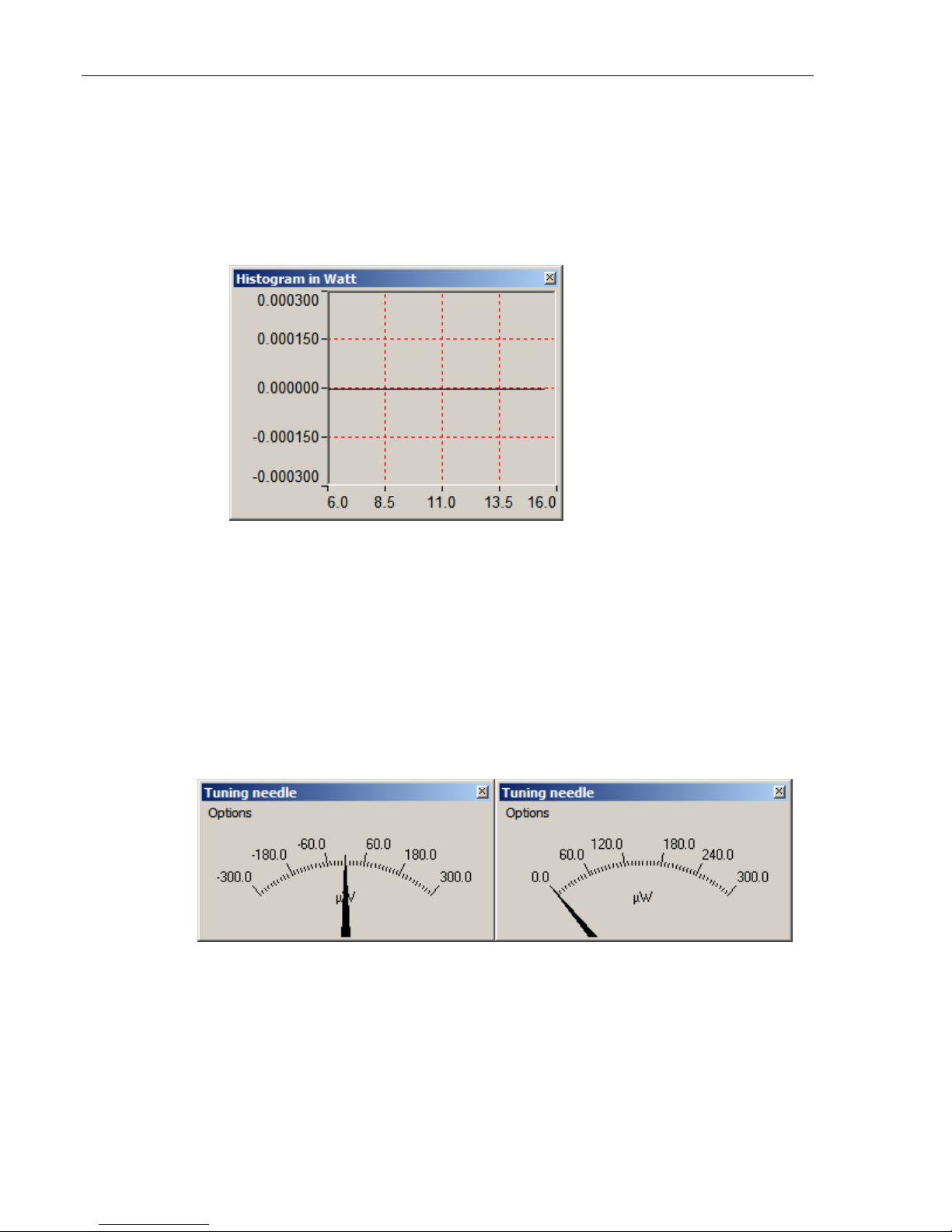
2.3.1.1 Histogram
Figure 2.2 Histogram
Right-click on the histogram to set the time period to view (Set X Axis…),
reset the display or select a scale. Note that the Auto-Scale on the histogram
starts from the lowest scale and only does scale-ups. This is made to select
the best scale for the user without frequent scale oscillations.
2.3.1.2 Tuning Needle
Figure 2.3 Tuning Needle (2 options)
Right-click on the Tuning Needle to select a scale. The autoscale (default) is
useful when the measurement variations are small, because it will zoom on

the best possible scale, but will oscillate with large variations. Use a fixed
scale in this case.
2.3.1.3 Status
Figure 2.4 Status window example
The Status window displays the detector name and various settings.
2.3.1.4 Statistics
Figure 2.5 Statistics in power and energy mode

10
The statistics window displays the current statistics. See section 2.3.2.2 to
set the data sampling parameters and to start and stop the statistics.
2.3.2 Settings Menu
Options in the Settings menu define user-adjustable acquisition parameters.
All correction factors that will affect the reading can be easily programmed.
That could be for a beam sampler, attenuator, or other optics that require you
to multiply and/or add offsets to the detector reading. You can also adjust for
a wavelength other than the calibration wavelength. A custom correction
factor can also be keyed in. Pre-programmed wavelength correction factors
dedicated to each detector head are also available and automatically loaded
from the detector EEPROM. Data sampling and trigger level, as well as the
commands for saving and loading your settings are also found in the Settings
menu. For more information on wavelength correction, see Wavelength
Setting, immediately below.
Figure 2.6 Settings menu
2.3.2.1 Wavelength Setting
Use the Wavelength menu to select the proper wavelength at which the
detector is to be used. It applies a correction to adjust for the variation in
responsivity at different wavelengths. When a new detector is connected to
the meter, and the application has been closed and re-opened, the calibration
wavelength is the default selection.
The checkmark beside the wavelength clearly shows the current selection.
To change the wavelength, select an appropriate wavelength from the
Table of contents


