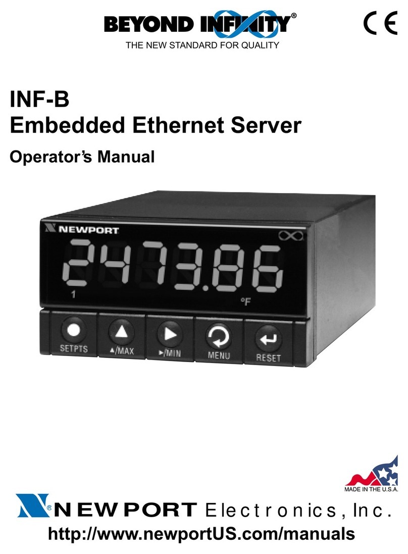
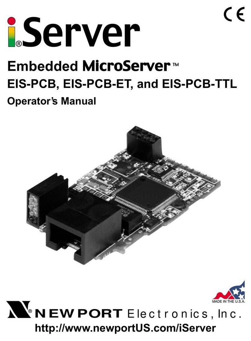
Newport iServer Series User manual

http://www.newportUS.com/iServer
®
NEWPORT
Electronics, Inc.
Ethernet Server
Operator’s Manual

Counters
Frequency Meters
PID Controllers
Clock/Timers
Printers
Process Meters
On/Off
Controllers
Recorders
Relative
Humidity
Transmitters
Thermocou les
Thermistors
Wire
Rate Meters
Timers
Totalizers
Strain Gauge
Meters
Voltmeters
Multimeters
Soldering Iron
Testers
H ens
H Controllers
H Electrodes
RTDs
Thermowells
Flow Sensors
For Immediate Assistance
In the U.S.A. and Canada: 1-800-NEWPORT
®
In Mexico: (95) 800-NEWPORT
SM
Or call your local NEWPORT Office.
Internet e-mail
info@new ortUS.com
Additional roducts from
NEWPO TnetSM On-Line Service
www.new ortUS.com
®
NEWPORT
Electronics, Inc.
It is the olicy of NEWPORT to com ly with all worldwide safety and EMC/EMI regulations that a ly. NEWPORT is constantly
ursuing certification of its roducts to the Euro ean New A roach Directives. NEWPORT will add the CE mark to every
a ro riate device u on certification.
The information contained in this document is believed to be correct but NEWPORT Electronics, Inc. acce ts no liability for any
errors it contains, and reserves the right to alter s ecifications without notice.
WARNING: These roducts are not designed for use in, and should not be used for, atient connected a lications.
TRADEMARK NOTICE:
, NEWPORT and NEWPORT
®
are trademarks of NEWPORT Electronics, Inc.
PATENT NOTICE: This roduct is covered by one or more of the following atents: U.S. Pat. No. Des. 336,895; 5,274,577/
CANADA 2052599; 2052600/ ITALY 1249456; 1250938 / FRANCE BREVET No. 91 12756 / SPAIN 2039150; 2048066 / UK
PATENT No. GB2 249 837; GB2 248 954 / GERMANY DE 41 34398 C2. The ™is a Trademark of OMEGA Engineering, Inc.
Used Under License. Other US and International Patents ending or a lied for.
This device is marked with the international caution symbol. It is im ortant to read the Setu Guide before installing or
commissioning this device as it contains im ortant information relating to safety and EMC.

TABLE OF CONTENTS
Part 1: Introduction ...........................................................................................2
1.1 Safety and EMC Considerations ................................................2
1.2 Before You Begin .........................................................................3
1.3 Description ...................................................................................4
Part 2: Hardware ...........................................................................................5
2.1 Physical Characteristics and Mounting of DIN ail Unit .........5
2.2 Front Panel of DIN ail Unit .......................................................6
2.3 ear Panel of iSeries Meter with iServer Built-in PCB ............6
2.4 Serial Communication Interfaces ..............................................8
2.4.1 Wiring S232 Interface ...................................................9
2.4.2 Wiring S485 Interface .................................................10
2.5 Network Communication Interfaces ........................................11
2.5.1 10Base-T J-45 Pinout ..................................................11
2.5.2 10Base-T Crossover Wiring ..........................................11
Part 3: Network Configuration .........................................................................12
3.1 Network Protocols ....................................................................12
3.2 Ethernet (MAC) Address ..........................................................12
3.3 IP Address .................................................................................12
3.3.1 Default IP Address ........................................................13
3.4 Subnetting .................................................................................13
3.5 Port Number ..............................................................................13
Part 4: Serial Interface Configuration .............................................................14
4.1 Communication Protocol .........................................................14
4.2 Command Structure .................................................................14
4.3 Command Formats ...................................................................14
Part 5: Operations .........................................................................................16
5.1 Modifying the IP Address .........................................................16
5.2 HTTPGET Program ...................................................................18
5.3 A P Protocol .............................................................................19
5.4 Setup and Operation using the iServer Web Page ................21
5.4.1 ead Devices .................................................................22
5.4.2 Send aw Command .....................................................23
5.4.3 Modify Device List Entry ...............................................23
5.4.4 Serial Port Configuration ..............................................24
5.4.5 Configure Access Control ............................................25
5.4.6 Log In ..............................................................................26
5.4.7 Change ID .......................................................................26
5.5 Mail Notifier Software ...............................................................27
5.5.1 Installation ......................................................................27
5.5.2 Program Options Setup and Configuration ................28
5.5.3 Device Setting Setup and Configuration .....................29
i

Part 6: Specifications .......................................................................................30
Part 7: Factory Preset Values ..........................................................................31
Part 8: Approvals Information .........................................................................32
8.1 Electromagnetic Compatibility (EMC) .....................................32
8.2 FCC .........................................................................................32
Appendix A Glossary .....................................................................................33
Appendix B IP Address .................................................................................34
Appendix C IP Netmask .................................................................................35
Appendix D ASCII Chart ................................................................................36
ASCII Chart Control Codes ......................................................37
LIST OF FIGURES:
Figure 1.1 iServer on the Ethernet Network ................................................4
Figure 2.1 iServer Dimensions and Mounting ............................................5
Figure 2.2 Front Panel View of the iServer DIN ail Unit ..........................6
Figure 2.3 ear Panel View of i16/i18 Meters with Embedded iServer .....6
Figure 2.4 Wiring - iServer Serial Port and Device with S232 port .........9
Figure 2.5 Multi-point, Half-Duplex S485 Wiring ....................................10
Figure 2.6 J45 Connector Pinout .............................................................11
Figure 2.7 10Base-T Crossover Cable Wiring ..........................................11
Figure 3.1 Labeling .....................................................................................12
Figure 5.1 arp -a Commands and esponses ..........................................20
Figure 5.2 iServer Home Page ...................................................................21
Figure 5.3 iServer Mail Notifier Main Window ...........................................27
Figure 5.4 iServer Mail Notifier Profile Setup............................................28
Figure 5.5 iServer Mail Notifier Device Setting ........................................29
LIST OF TABLES:
Table 2.1 Front Panel Annunciators...........................................................7
Table 2.2 Communication Interfaces - S232 and S485 .......................8
Table 2.3 Pin Connection Assignments.....................................................9
Table 2.4 S485 Half-Duplex Hookup ......................................................10
Table 4.1 Command Prefix Letters...........................................................14
Table 4.2 Command Formats....................................................................14
ii

NOTES, WARNINGS and CAUTIONS
Information that is es ecially im ortant to note is identified by following labels:
• NOTE
• WA NING or CAUTION
• IMPO TANT
• TIP
NOTE: Provides you with information that is im ortant to successfully
setu and use the Programmable Digital Meter.
CAUTION or WA NING: Tells you about the risk of electrical shock.
CAUTION, WA NING or IMPO TANT: Tells you of circumstances or
ractices that can effect the instrument’s functionality and must refer
to accom anying documents.
TIP: Provides you hel ful hints.
1

PA T 1
INTRODUCTION
1.1 Safety and EMC Considerations
The instrument is a Class III device (10 to 32 VDC).
Always use a ower su ly, which com lies with EN 60950 safety standard.
EMC Considerations
•Whenever EMC is an issue, always use shielded cables.
•Never run signal and ower wires in the same conduit.
•Use signal wire connections with twisted- air cables.
•Install Ferrite Bead(s) on signal wires close to the instrument if EMC roblems ersist.
Failure to follow all instructions and warnings may result in injury!
2

1.2 Before You Begin
Inspecting Your Shipment:
Remove the acking sli and verify that you have received everything listed. Ins ect the
container and equi ment for signs of damage as soon as you receive the shi ment. Note
any evidence of rough handling in transit. Immediately re ort any damage to the shi ing
agent. The carrier will not honor damage claims unless all shi ing material is saved for
ins ection. After examining and removing the contents, save the acking material and
carton in the event reshi ment is necessary.
Customer Service:
If you need assistance, lease contact the Customer Service De artment nearest you.
Manuals, Software:
The latest O eration Manual as well as free iSeries configuration software and iServer
Mail Notifier are available at the website listed on the cover page of this manual or
on the CD- OM enclosed with your shipment.
3

1.3 Description
This device can be purchased as a stand alone DIN ail mounted unit, or
as an option for an iSeries monitor/controller (Embedded Ethernet Server)
with a S485 communication port interface. Some iSeries
monitors/controllers do not utilize S485 communications. In such
models, the S485 instructions do not apply.
The iServer is a stand alone Ethernet Server designed to connect industrial devices with
serial interfaces to the Ethernet network using the TCP/IP rotocol. It contains an
Ethernet Server and RS-232/485/422 interfaces.
The standard features include:
• Use standard Web Browser (TCP/IP rotocol) or HTTPGET DOS rogram for network
connectivity.
• Install via RS-232/485/422 serial ort connection.
• Transfer data from RS-232/485/422 serial interface to TCP/IP using built-in socket
server.
• Use a standard home age or customize web age using s ecial a lets, which are
available on our website.
The following exam le illustrates how you can hooku the devices with serial interface
on the net using the iServer:
Figure 1.1 iServer on the Ethernet Network
888.8
888.8
4

PA T 2
HARDWARE
2.1 Physical Characteristics and Mounting of DIN ail Unit
Figure 2.1 iServer Dimensions and Mounting
Mounting on DIN ail (refer to the Figure 2.1)
To install unit onto DIN Rail:
a) Tilt unit, osition ada ter guide onto DIN Rail.
b) Push unit towards DIN Rail and it will sna into lace.
emoval of unit
The ada ter can remain on DIN Rail and the iServer can be removed.
a) While holding the ada ter, ush unit u wards and the unit will detach from the
ada ter.
5

2.2 Front Panel of DIN ail Unit
Figure 2.2 Front Panel View of the iServer DIN ail Unit
6

Table 2.1 Front Panel Annunciators
Serial Communication Interface Section:
TX Transmit Wire connection (-Rx/-Tx for RS485 interface)
X Receive Wire connection (+Rx/+Tx for RS485 interface)
TN Return, Common Ground Wire connection
Network Communication Interface Section:
Ethernet RJ45 Female Connector for 10BASE-T connection
eset Reset button used to change an IP Address and reset to the default
assword
X LED (Green) Flashing: Indicates transmission from the Serial ort
ON: Indicates that the reset button is momentarily ushed
TX LED (Yellow) Flashing: Indicates rece tion to the Serial ort
ON: Indicates that the reset button is momentarily ushed
ON LED (Green) ON: Indicates Power On. Flashing: Indicates connection to
network host established
COL LED (Red) ON: Indicates that the Ethernet communication colla sed due
to high network traffic
DC Power Supply Section:
+Plus Power Su ly Wire connection
-Minus Power Su ly Wire connection
NC No connection
Both X and TX stay ON when the reset button is pushed. They turn OFF
after a new IP address has been entered.
7

2.4 Serial Communication Interfaces
Two communication interfaces are su orted in the iServer: RS232 and RS-485. These
standards define the electrical characteristics of a communication network. The RS485
ort of the iServer is fully com atible for use with RS422 instruments. The RS485 is an
extended version of the RS422 communication standard which increases the allowable
number of devices from 10 to 32 by im roving the electrical characteristics.
The iSeries controller/monitor with the embedded iServer o tion board su ort
only RS485/422 interfaces.
• The S232 standard (point-to-point) allows a single device to be connected to an
iServer. The iServer o erates with full-du lex RS232 using three wires: an
Rx-receives wire, an Tx-transmits wire, and a common ground wire. RS232 cable
length is limited to 50 feet.
• The S485 standard (multi-point) allows one or more devices (multi-dro ed) to be
connected to the iServer using a two-wire connection (half-du lex) +Rx/+Tx and
–Rx/-Tx. Use of RS485 communications allows u to 32 devices to connect to the
iServer with cable length u to 4000 feet long.
Although the RS485 is commonly referred to as a "two wire" connection, the
iServer also rovides a ground/return shield connection to use as a common
connection for EMI noise rotection.
Table 2.2 shows the differences between RS232 and RS485 communication interfaces.
Table 2.2
Data Transmission Characteristics S232 S485
Transmission Mode Single ended Differential
Electrical connections 3 wire 2 wire
Drivers er line 1 driver 32 drivers
Receivers er line 1 receiver 32 receiver
Maximum data rate 20k bits/s 10M bits/s
Maximum cable length 50 ft (15 meters) 4000 ft (1200 meters)
Changing between RS232 and RS485 interfaces, as well as modifying the other
arameters is ossible through the iServer home age (see Part 5 for details).
8

2.4.1 Wiring S232 Interface
Figure 2.4 Wiring between the iServer Serial Port and Device with S232 Port
Table 2.3 shows the in connection assignments between the iServer serial ort and
device with RS232 serial communication interface.
Table 2.3
iServer DEVICE WITH S232
Tx (Transmit) Rx (Receive)
Rx (Receive) Tx (Transmit)
RTN (Common GND) RTN (Common GND)
9
RTN TX RX

2.4.2 Wiring S485 Interface
RS485 interface uses a two-wire communication system (one for transmitting and one for
receiving) lus a common wire to connect to the shield of the cable. It is recommended
to use a shielded cable with one twisted air.
Use of twisted air and shield will significantly im rove noise immunity.
Figure 2.5 shows multi- oint, half-du lex RS485 interface connections for the iServer.
Figure 2.5 Multi-point, Half-Duplex S485 Wiring
Value of the termination resistor is not critical and de ends on the cable
im edance.
Table 2.4 shows RS485 half-du lex hooku between the iServer serial ort and device
with RS485 communication interface.
Table 2.4
iServer DEVICE WITH S485
+Tx/+Rx (+Transmit/+Receive) +Tx/+Rx (+Transmit/+Receive)
-Tx/-Rx (-Transmit/-Receive) -Tx/-Rx (-Transmit/-Receive)
RTN (Common GND) GND (Common GND)
10
DEVICE #1 DEVICE #29
DEVICE #31
DEVICE #30
DEVICE #2
iServer
120 Ohm
Termination resistor 120 Ohm
Termination resistor
GND
-Tx/-Rx
+Tx/+Rx
+Tx/+Rx
-Tx/-Rx
Twisted shielded pair
-Tx/-Rx
-Tx/-Rx-Tx/-Rx
-Tx/-Rx
+Tx/+Rx
+Tx/+Rx
GND
GND
GND
GND
+Tx/+Rx
+Tx/+Rx
.........................
.........................
...............................
...............................

2.5 Network Communication Interfaces
2.5.1 10Base-T J-45 Pinout
The 10BASE-T Ethernet network (RJ-45) system is used in the iServer for network
connectivity. The 10 Mb s twisted- air Ethernet system o erates over two airs of wires.
One air is used for receiving data signals and the other air is used for transmitting data
signals. This means that four ins of the eight- in connector are used.
Figure 2.6 J45 Pinout
2.5.2 10Base-T Crossover Wiring
When connecting the iServer directly to the com uter, the transmit data ins of the
com uter should be wired to the receive data ins of the iServer, and vice versa. The
10Base-T crossover cable with in connection assignments are shown on Figure 2.7.
Figure 2.7 10Base-T Crossover Cable Wiring
Use straight through cable for connecting the iServer to the Ethernet network.
Crossover will be done inside a hub.
11
Pin Name Description
1 +Tx + Transmit Data
2 -Tx - Transmit Data
3 +RX + Receive Data
4 N/C Not Connected
5 N/C Not Connected
6 -Rx - Receive Data
7 N/C Not Connected
8 N/C Not Connected

PA T 3
NETWORK CONFIGURATION
3.1 Network Protocols
The iServer can be connected to the network using standard TCP/IP rotocols.
It is also su orted by ARP and HTTP rotocols. TCP/IP networking rotocols are
su erim osed into a local Ethernet network until, if so desired, a connection is made to
the Internet.
3.2 Ethernet (MAC) Address
MAC (Media Access Control) address is your com uter's unique hardware number.
When you're connected to the Internet from your com uter, a corres ondence table
relates your IP address to your com uter's hysical (MAC) address on the LAN. The
MAC address can be found on the label of your device and contains 6 bytes (12
characters) of hexadecimal numbers XX:XX:XX:XX:XX:XX hex
For exam le: 0A:0C:3D:0B:0A:0B
You need to know this number to access the iServer to change the IP address.
There is room on the label to ut your IP address. See Figures 3.1.
Figure 3.1 Labeling
3.3 IP Address
Every active device connected to the TCP/IP network must have a unique IP address.
This IP address is used to build a connection to the iServer serial ort. Every com uter
using TCP/IP should have a unique 32-bit address. It is divided into two ortions, the
network ID and the host ID. For instance, every com uter on the same network uses the
same network ID. At the same time, all of them have a different host ID. For more details
about the IP address see A endix B.
12

3.3.1 Default IP Address
The iServer is shi ed with a default IP address set to 128.100.101.254.
If you are going to use a Web browser or HTTPGET rogram to access the device, make
sure that the default IP address is available to the instrument before rocessing.
If the factory default address is already in use in your network, use the Ethernet
crossover cable connected to one com uter to access the device and modify the IP
address from factory defaults.
3.4 Subnetting
Subnetting is the rocess of dividing a block of IP addresses assigned as a Class A, B,
or C network into multi le, smaller blocks of addresses. After they are divided, you can
use your network more efficiently. For more details about Subnetting see A endix C
(Subnet Masks).
3.5 Port Number
All TCP connections are defined by the IP address and a ort number. A ort number is
an internal address that rovides an interface between an a lication running on your
com uter and network through the TCP/IP rotocol software. Some services or
rocesses have conventionally assigned ermanent ort numbers.
There are two ermanent TCP socket ort numbers assigned to the iServer:
• A destination or well-known socket ort number that is assigned to a s ecific
a lication by IANA (Internet Assigned Numbers Authority). It serves as htt ort
number: 80
• Source socket ort number: 1000
13

PA T 4
SERIAL INTERFACE CONFIGURATION
An industrial device with serial interfaces (PLC, CNC controllers, PC, Data Dis lay
Devices, etc.) can be connected to the serial ort of the iServer.
4.1 Communication Protocol
A data communication rotocol defines the rules and structure of messages used by all
devices on a network for data exchange. A ty ical transaction will consist of a request to
send from the MASTER followed by the res onse from one or more SLAVE devices.
Either a single ( oint-to- oint) or multi-dro network (multi- oint) is ossible.
4.2 Command Structure
There are different command ty es associated with communication between the iServer
and your device shown in Table 4.1, which shows the Command Prefix Letters
(Command Classes)
Table 4.1 Command Prefix Letters
COMMAND P EFIX
(COMMAND CLASS) MEANING
^AE S ecial read, Communication arameters
P (Put) Write HEX data into RAM
W (Write) Write HEX data into EEPROM.
G (Get) Read HEX data from RAM
R (Read) Read HEX data from EEPROM
U Read status byte
V Read measurement data string in decimal format
X Read measurement data values in decimal format
D Disable
E Enable
Z Reset
4.3 Command Formats
Table 4.2 shows the command formats for the iServer.
Table 4.2 Command Formats
For "P" and "W" Command For "G" and " " Command For "X", "V", "U", "D", "E",
classes: classes: & "Z" Command classes:
Point-to-point mode Point-to-point mode Point-to-point mode
* ccc<data><cr> * ccc <cr> * ccc <cr>
Multi-point mode Multi-point mode Multi-point mode
* nnccc [<data>]<cr> * nnccc <cr> * nnccc <cr>
14

Where:
"*" is the selected Recognition Character. You may select any ASCII table symbol from
"!" (HEX address "21") to the right-hand brace (HEX "7D") exce t for the caret "^", "A",
"E", which are reserved for bus format request.
"ccc" stands for the hex-ASCII Command Class letter (one of eleven given in Table 4.1),
followed by the two hex-ASCII Command Suffix characters identifying the meter data,
features, or menu items to which the command is directed.
"<data>" is the string of characters containing the variable information the com uter is
sending to the meter. These data (whether BCD or binary) are encoded into hex-ASCII
character (see A endix D for binary-hex-ASCII chart), two characters to the byte.
Square brackets [indicating o tional status] enclose this string, since some commands
contain no data.
"<nn>" are the two ASCII characters for the device Bus Address of RS485
communication.
Use values from "00" to hex "C7" (199 decimal).
The following format is used for each byte sent and received through serial port of
iServer:
1. Seven or Eight-bit binary, Hexadecimal (0 ... 9, A ... F)
2. Two hexadecimal characters contained in each eight-bit field of the message
3. 1 start bit; 7 or 8 data bit; 1 Sto Bit; Odd, Even (No Parity) Bit
The figure below shows the bit sequences when a byte is transmitted or received
through the iServer.
LSB MSB
LSB – Least Significant bit
MSB – Most Significant bit
Least Significant beat sent first
15
START 1 2 3 4 5 6 7 8 STOP PARITY

PA T 5
OPERATIONS
5.1 Modifying the IP Address
The IP Address may be set via the network by using "Seti " DOS rogram.
The seti .exe file is used to set a new IP Address. This file will be automatically installed
when you run any iServer related software available on our website and CD.
Exam le to use the "seti " rogram:
1. Choose a qualified new IP address.
2. Make sure that the new IP address is available to the device before rocessing
by inging the new IP address:
"Ping.exe" file should be installed and available on each com uter configured to
use TCP/IP.
C:\ping 128.100.101.33
If you get the following res onse, it means that this IP address is not taken:
Pinging 128.100.101.33 with 32 bytes of data.
Request timed out:
Request timed out:
Request timed out:
Request timed out:
3. Create a directory C:\iServer\Seti
4. Co y seti .exe file to this directory.
Push the " eset" button on the iServer before roceeding to the next ste .
5. Make sure that you are on this directory and then enter "seti ", followed by the MAC
address and the new IP address:
C:\iServer\Setip\setip XX:XX:XX:XX:XX:XX DDD.DDD.DDD.DDD
or
C:\iServer\Setip\setip ddd.ddd.ddd.ddd.ddd.ddd DDD.DDD.DDD.DDD
where: XX:XX:XX:XX:XX:XX is a MAC address in hexadecimal
ddd.ddd.ddd.ddd.ddd.ddd is a MAC address in decimal
DDD.DDD.DDD.DDD is a new IP address in decimal
16
Table of contents
Other Newport Server manuals
Popular Server manuals by other brands
Supermicro
Supermicro 5025M-4 user manual
Moxa Technologies
Moxa Technologies NPort 5200A Series user manual
SmartSight
SmartSight S1500e Series user manual
Sun Microsystems
Sun Microsystems Sun Fire X4100 Service manual

Zoom
Zoom AERO RYTHMTRAK AR-96 Quick manual

Lenovo
Lenovo ThinkServer TS200 Installation and user guide
