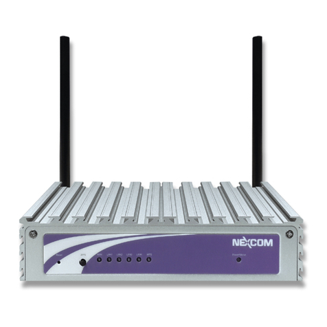
Nexcom IWF2220 User manual

User Manual
Light Industrial Access Point
IWF2220
V1.2

User’s Manual
Light Industrial AP ENGLISH
1
Copyright © NEXCOM, INC.
Copyright & Disclaimer
Copyright
The contents of this publication may not be reproduced in any part or as a whole, stored,
transcribed in an information retrieval system, translated into any language, or transmitted in any
form or by any means, mechanical, magnetic, electronic, optical, photocopying, manual, or
otherwise, without the prior written permission of NEXCOM, INC.
Disclaimer
NEXCOM, INC. does not assume any liability arising out the application or use of any products, or
software described herein. Neither does it convey any license under its parent rights not the parent
rights of others. NEXCOM further reserves the right to make changes in any products described
herein without notice. The publication is subject to change without notice.
Trademarks
NEXCOM is a registered trademark of NEXCOM, INC. Other trademarks mentioned in this publication
are used for identification purposes only and may be properties of their respective owners.
FCC Statement:
Federal Communication Commission Interference Statement
This equipment has been tested and found to comply with the limits for a Class B digital device,
pursuant to Part 15 of the FCC Rules. These limits are designed to provide reasonable protection
against harmful interference in a residential installation. This equipment generates, uses and can
radiate radio frequency energy and, if not installed and used in accordance with the instructions,
may cause harmful interference to radio communications. However, there is no guarantee that
interference will not occur in a particular installation. If this equipment does cause harmful
interference to radio or television reception, which can be determined by turning the equipment off
and on, the user is encouraged to try to correct the interference by one of the following measures:
● Reorient or relocate the receiving antenna.

User’s Manual
Light Industrial AP ENGLISH
2
Copyright © NEXCOM, INC.
● Increase the separation between the equipment and receiver.
● Connect the equipment into an outlet on a circuit different from that to which the receiver is
connected.
● Consult the dealer or an experienced radio/TV technician for help.
FCC Caution: Any changes or modifications not expressly approved by the
party
responsible for compliance could void the user’s authority to operate this
equipment.
This device complies with Part 15 of the FCC Rules. Operation is subject to the following two
conditions: (1) This device may not cause harmful interference, and (2) this device must accept any
interference received, including interference that may cause undesired operation.
For product available in the USA/Canada market, only channel 1~11 can be operated. Selection of
other channels is not possible.
This device and it's antennas(s) must not be co-located or operating in conjunction with any other
antenna or transmitter except in accordance with FCC multi-transmitter product procedures.
This device is going to be operated in 5.15~5.25GHz frequency range, it is restricted in indoor
environment only.
IMPORTANT NOTE:
FCC Radiation Exposure Statement:

User’s Manual
Light Industrial AP ENGLISH
3
Copyright © NEXCOM, INC.
This equipment complies with FCC radiation exposure limits set forth for an uncontrolled environment.
This equipment should be installed and operated with minimum distance 20cm between the
radiator & your body.
Warning!
You are cautioned that changes or modifications not expressly approved by the party responsible
for compliance could void your authority to operate the equipment.
1. Handling the unit: carry the unit with both hands and handle it with care.
2. Maintenance: to keep the unit clean, use only approved cleaning products or cleans with a dry cloth.

User’s Manual
Light Industrial AP ENGLISH
4
Copyright © NEXCOM, INC.
Table of Contents
1. Before You Start ..................................................................................................................................6
1.1 Preface.................................................................................................................................................6
1.2 Document Conventions....................................................................................................................6
1.3 Package Content................................................................................................................................7
2. System Overview and Getting Started .............................................................................................8
2.1 Introduction of NEXCOM Access Points.......................................................................................8
2.2 Hardware Description......................................................................................................................9
2.3 Hardware Installation....................................................................................................................11
2.4 Access Web Management Interface.............................................................................................12
3. Connect your AP to your Network..................................................................................................15
4. Adding Virtual Access Points ..........................................................................................................21
5. Securing the AP .................................................................................................................................23
6. Creating a WDS Bridge between two APs......................................................................................35
7. Web Management Interface Configuration...................................................................................38
7.1 System...............................................................................................................................................40
7.1.1 General ............................................................................................................................40
7.1.2 Network Interface...........................................................................................................42
7.1.3 Port..................................................................................................................................43
7.1.5 CAPWAP .........................................................................................................................46
7.1.6 IPv6 ................................................................................................................................. 47
7.2 Wireless............................................................................................................................................48
7.2.1 VAP Overview .................................................................................................................48
7.2.2 General ...........................................................................................................................50
7.2.3 VAP Configuration ......................................................................................................... 54
7.2.4 Security........................................................................................................................... 55
7.2.5 Repeater ......................................................................................................................... 59
7.2.6 Advanced ........................................................................................................................60
7.2.7 Access Control ................................................................................................................62
7.3 Firewall.............................................................................................................................................66
7.3.1 Firewall List ....................................................................................................................66
7.3.2 Service ............................................................................................................................70
7.3.3 Advanced .........................................................................................................................71
7.4 Utilities.............................................................................................................................................72
7.4.1 Change Password............................................................................................................ 72
7.4.2 Backup & Restore........................................................................................................... 72
7.4.3 System Upgrade ............................................................................................................. 74

User’s Manual
Light Industrial AP ENGLISH
5
Copyright © NEXCOM, INC.
7.4.4 Reboot ............................................................................................................................ 74
7.4.5 Upload Certificate .......................................................................................................... 75
7.4.6 Channel Analysis............................................................................................................ 75
7.5 Status ................................................................................................................................................77
7.5.1 Overview ......................................................................................................................... 77
7.5.2 Associated Clients ..........................................................................................................78
7.5.3 WDS Link Status ............................................................................................................ 79
7.5.4 Event Log........................................................................................................................80

User’s Manual
Light Industrial AP ENGLISH
6
Copyright © NEXCOM, INC.
1.Before You Start
1.1 Preface
This manual is intended for using by system integrators, field engineers and network administrators to help
them set up Access Points in their network environments. It contains step by step procedures and pictures to
guide users with basic network system knowledge to complete the installation.
1.2 Document Conventions
Represents essential steps, actions, or messages that should not be ignored.
Note:
Contains related information that corresponds to a topic.
Indicates that clicking this button will save the changes you made, but you must reboot
the system for the changes to take effect.
Indicates that clicking this button will clear what you have set before the settings are
applied.

User’s Manual
Light Industrial AP ENGLISH
7
Copyright © NEXCOM, INC.
1.3 Package Content
The standard package of IWF2220 includes:
NEXCOM IWF2220 x1
CD-ROM (with User’s Manual and QIG) x1
Ethernet Cable x1
Power cord x1
Power Adaptor (12V) x1
Detachable Antenna x4
It is recommended to keep the original packing materials for possible future shipment when repair or
maintenance is required. Any returned product should be packed in its original packaging to prevent
damage during delivery.

User’s Manual
Light Industrial AP ENGLISH
8
Copyright © NEXCOM, INC.
2. System Overview and Getting Started
2.1 Introduction of NEXCOM Access Points
Indoor –IWF2220
The NEXCOM’s Enterprise Access Point IWF Series are embedded with 802.11 a/b/g/n MIMO
technology, designed for seamless wireless connectivity in enterprise or industrial environments of all
dimensions. IWF2220 features dual radio RF cards to offer flexible implementations needed for the
growing wireless networking applications. The IWF Series make wireless communication fast, secure and
easy. They support business grade security, namely 802.1X, and Wi-Fi Protected Access (WPA and
WPA2). By pushing a purposely built button, the WES (Press-n-Connect) feature makes it easy to bridge
wireless links of multiple access points for forming a wider wireless network coverage.
The IWF Series also features multiple ESSIDs with VLAN tags and multiple Virtual APs, great for
enterprise applications, such as separating traffic from different departments using different ESSIDs. The
PoE LAN port is able to receive power from Power over Ethernet (PoE) sourcing devices.
Please note that screenshots are taken from APs which feature dual RF cards. Single RF
Card APs can be configured in the same manner from the User Interface.

User’s Manual
Light Industrial AP ENGLISH
9
Copyright © NEXCOM, INC.
2.2 Hardware Description
This section depicts the hardware information including all panel description.
IWF2220
Front Panel
IWF2220 Front Panel

User’s Manual
Light Industrial AP ENGLISH
10
Copyright © NEXCOM, INC.
Rear Panel
IWF2220 Rear Panel
1
Restart / Reset
Press once to restart the system; to reset the system to factory default
settings, hold for more than 5 seconds.
2
WES Button (RF B)
WDS Easy Setup. Press the button to build up a WDS link with another
peer. 4 WDS links can be set up per RF card. Note that the WES Button
only runs on the 5 GHz RF Card B.
3
LAN 1~4 Ports
The ports for connections with LAN side devices.
4
Uplink Port (PoE)
The port for uplink connection to another gateway or device. PoE
(802.3at) is supported.
5
12V 2A
Power Socket for the power adaptor

User’s Manual
Light Industrial AP ENGLISH
11
Copyright © NEXCOM, INC.
2.3 Hardware Installation
Please follow the steps mentioned below to install the hardware of IWF2220:
Step 1. Place the IWF2220 at the best location. The best location is usually at the center of your intended
wireless network.
Step 2. Connect the IWF2220 to your network device. Connect one end of the Ethernet cable to the Uplink
port of IWF2220 and the other end of the cable to a switch, a router, or a hub. IWF2220 is then
connected to your existing wired LAN network.
Step 3. There are two ways to supply power to IWF2220
a) Connect the DC power adaptor to the IWF2220 power jack socket.
b) The IWF2220 Uplink port is capable of receiving DC currents. Connect a (IEEE 802.3at-
compliant) PSE device (e.g. a PoE-switch) to the Uplink port of IWF2220 with the Ethernet cable.
Now, the Hardware Installation is complete.
Please use only the power adapter supplied with the package. Using a different power
adapter may damage this system.
To verify the wired connection between the AP and your switch / router / hub, please also
check the LED status indicator of the respective network devices.

User’s Manual
Light Industrial AP ENGLISH
12
Copyright © NEXCOM, INC.
2.4 Access Web Management Interface
NEXCOM Access Points support web-based configuration. When hardware installation is complete, the AP
can be configured through a PC by using a web browser.
The default values of the AP’s LAN IP Address and Subnet Mask are:
IP Address: 192.168.1.1
Subnet Mask: 255.255.255.0
Example of entering the AP's default IP Address into a web browser
To access the web management interface (WMI), connect the administrator PC to the LAN port of the
AP via an Ethernet cable. Then, set a static IP Address on the same subnet mask as the AP in
TCP/IP settings of your PC, such as the following example:
IP Address: 192.168.1.100
Subnet Mask: 255.255.255.0
Note:
Please note that the IP Address used should not overlap with the IP Addresses of
any other device within the same network to avoid IP conflict.
Launch the web browser on your PC and enter the IP Address of the AP (192.168.1.1) at the address
field, and then press Enter. The following Administrator Login Page will appear. Enter “admin” for
both the Username and Password fields, and then click Login.

User’s Manual
Light Industrial AP ENGLISH
13
Copyright © NEXCOM, INC.
Administrator Login Page
After a successful login into AP, a System Overview page of the Web Management Interface (WMI)
will appear.
The Web Management Interface - System Overview Page
To logout, simply click on the Logout button at the upper right hand corner of the interface to return to
the Administrator Login Page. Click OK to logout.

User’s Manual
Light Industrial AP ENGLISH
14
Copyright © NEXCOM, INC.
Logout Prompt
For security reasons, it is strongly recommended to change the administrator’s password upon the
completion of all configuration settings
Please follow the following steps to change the administrator’s password:
Change Password Page
Click on the Utilities icon on the main menu, and select the Change Password tab.
Enter the old password and then a new password with a length of up to 32 characters, and retype it in
the Re-enter New Password field.
Congratulation!
Now, the NEXCOM Access Point is installed and configured successfully.
It is strongly recommended to make a backup copy of your configuration settings.
After the AP’s network configuration is completed, please remember to change the IP Address
of your PC Connection Properties back to its original settings in order to ensure that your PC
functions properly in its real network environments.

User’s Manual
Light Industrial AP ENGLISH
15
Copyright © NEXCOM, INC.
3. Connect your AP to your Network
The following instructions depict how to establish the wireless coverage of your network. The AP will
connect to the network through its LAN port and provide wireless access to your network.
After having prepared the AP’s hardware for configuration, set the TCP/IP settings of administrator’s
computer to have a static IP Address of 192.168.1.10 and Subnet Mask of 255.255.255.0.
Step 1: Configuring the AP’s System Information
Enter the AP’s default IP Address (192.168.1.1) into the URL of a web browser.
Log in using Username: admin and Password: admin.
The Web Management Interface will appear as shown below.

User’s Manual
Light Industrial AP ENGLISH
16
Copyright © NEXCOM, INC.
Web Management Interface Main Page (System Overview)
From here, click on the System icon to get to the following page. On this Page you can make entries
to the Name, Description, and Location fields as well as set the device’s time.
System Information Page
There are two methods of setting up the time: Manual (indicated by the option Set Date & Time) and
NTP.
The default is Manual and requires individual setup every time the system starts up. Simply choose a
time zone and set the time accordingly. When it is finished, click SAVE.
Manually Time Setup
The alternative method is NTP. Upon selecting NTPunder the Time field, the configuration changes
to allow up to two NTP servers. Simply enter a local NTP server’s IP Address (if available) or search
online for an NTP server nearest to you. Set the time zone and click SAVE.

User’s Manual
Light Industrial AP ENGLISH
17
Copyright © NEXCOM, INC.
NTP Setup
Step 2: Configuring the AP’s Network Settings
While still on this Page, click on the Network Interface tab to begin configuration of the network
settings.
Network Settings Page
If the deployment decides that the AP will be getting dynamic IP Addresses from the connected
network, set Mode to DHCP; otherwise, set Mode to Static and fill in the required fields marked with
a red asterisk (IP Address, Netmask, Gateway, and Primary DNS Server) with the appropriate
values for the network. Click SAVE when you are finished to save changes that have been made.
Step 3: Configure the AP’s Wireless General Settings
Click on the Wireless icon followed by the General tab. On this page we need to choose the Band
and Channel that we wish to use.

User’s Manual
Light Industrial AP ENGLISH
18
Copyright © NEXCOM, INC.
Wireless General Settings Page
On this page, choose the RF card you would like to set up and select the band in which the AP is to
broadcast its signal. The rest of the fields are optional and can be configured at another time. Click
SAVE if any changes have been made.
Note:
•For IWF2220, the RF Card A supports only 2.4GHz bands (b/g/n) and RF Card B supports
only 5GHz bands (a/n).

User’s Manual
Light Industrial AP ENGLISH
19
Copyright © NEXCOM, INC.
Step 4: Configuring Wireless Coverage (VAP-1)
To set up the AP’s wireless access, refer to the following VAP-1 configuration (other VAP
configuration can refer to the same setup steps as done for VAP-1). Click on the Overview tab to
proceed.
Virtual AP Overview Page
On this page click the hyperlink in the row and column that corresponds with VAP-1’s State. This will
bring up the following page.
Table of contents
Other Nexcom Wireless Access Point manuals