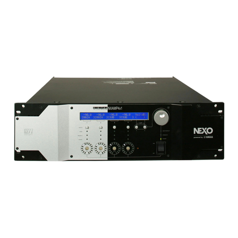
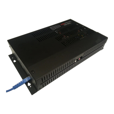
Nexo DTDAMP4x0.7 User manual

DTDAMPAmplifiers
DTDAMP4x0.7
DTDAMP4x1.3
User Manual v1.1

FCC INFORMATION (U.S.A.)
PAGE 2 OF 8
FCC information(U.S.A.)
1. IMPORTANT NOTICE:DO NOT MODIFY THIS UNIT!
This product, when installed as indicated in the instructions contained in this
manual, meets FCC requirements. Modifications not expressly approved by
NEXO-SA mayvoidyour authority,grantedbytheFCC,to usetheproduct.
2. IMPORTANT:
When connecting this product to accessoriesand/or another product use only
high quality shielded cables. Cable/ssupplied with thisproduct MUST be used.
Follow all installation instructions. Failure to follow instructionscould void your
FCCauthorizationtousethisproduct intheUSA.
3. NOTE:
Thisproduct hasbeentestedandfoundtocomplywiththerequirementslistedin
FCC Regulations, Part 15 for Class “B” digital devices. Compliance with these
requirements provides a reasonable level of assurance that your use of this
product in aresidential environment will not result in harmful interference with
other electronic devices. Thisequipment generates/usesradio frequencies and, if
not installed and used according to the instructions found in the user’s manual,
may cause interference harmful to the operation of other electronic devices.
Compliance with FCC regulationsdoes not guarantee that interference will not
occur inall installations. If thisproduct isfound to bethesourceof interference,
which can be determined by turning the unit “OFF” and “ON”, please try to
eliminatetheproblembyusingoneofthefollowingmeasures:
Relocate either this product or the device that is being affected by the
interference.
Utilizepower outletsthat areondifferent branch(circuit breaker or fuse) circuits
or installAClinefilter/s.
In the case of radio or TV interference, relocate/reorient the antenna. If the
antennalead-inis300ohmribbonlead,changethelead-into co-axial typecable.
If these corrective measures do not produce satisfactory results, please contact
thelocal retailer authorizedto distributethistypeof product.Ifyoucannot locate
theappropriateretailer, pleasecontact theAfter Salesdepartment of NEXO-SA,
Parc d’Activité du Pré de la Dame Jeanne, B.P. 5, 60128 PLAILLY,FRANCE.
The above statementsapply ONLY to those productsdistributed by NEXO-SA
or itssubsidiaries.
* Thisappliesonlyto productsdistributedintheUnitedStatesofAmerica.
Important safetyinstructions
1Readtheseinstructions.
2Keeptheseinstructions.
3Heedallwarnings.
4Followallinstructions.
5Donot usethisapparatusnear water.
6Cleanonlywithdrycloth.
7 Do not block any ventilation openings. Install in accordance with the
manufacturer’s instructions.
8Do not installnear anyheat sourcessuchasradiators,heat registers, stoves,or
other apparatus(includingamplifiers) that produceheat.
9 Do not defeat the safety purpose of the polarized or grounding-type plug. A
polarized plughas two blades with one wider than the other. A grounding type
plug has two blades and a third grounding prong. The wide blade or the third
prong is provided for your safety. If the provided plug does not fit into your
outlet,consult anelectricianfor replacement oftheobsoleteoutlet.
10Protect thepower cordfrombeingwalkedonor pinchedparticularlyat plugs,
conveniencereceptacles,andthepoint wheretheyexit fromtheapparatus.
11Onlyuseattachments/accessoriesspecifiedbythemanufacturer.
12Unplugthisapparatusduringlightningstormsor whenunusedfor longperiods
oftime.
13 Refer all servicingto qualified servicepersonnel.Servicingisrequired whenthe
apparatushasbeen damaged in any way, such as power-supply cord or plug is
damaged, liquid has been spilled or objects have fallen into the apparatus, the
apparatushasbeen exposed to rain or moisture, doesnot operate normally, or
hasbeendropped.
Precautions
Pleasereadcarefullybeforeproceeding.Pleasekeep thismanual inasafeplacefor
futurereference.
WARNING! Alwaysfollow the basic precautionslisted below to avoid
the possibility of serious injury or even death from electrical shock, short-
circuiting, damages, fire or other hazards. These precautionsinclude, but are not
limitedto,thefollowing:
Power supply/Power cord
• Only use the voltage specified as correct for the device. The required voltageis
printedonthenameplateofthedevice.
• Use only the included power cord if any.
• Do not place the power cord near heat sources such as heaters or radiators,
and do not excessively bend or otherwisedamage the cord, place heavy objects
on it, or place it in aposition where anyone could walk on, trip over, or roll
anythingover it.
• Be sure to connect to an appropriate outlet with a protective grounding
connection.Improper groundingcanresult inelectrical shock.
• Remove the electric plug fromtheoutlet when thedeviceisnot to beusedfor
extendedperiodsoftime,or duringelectricalstorms.
• When removing the electric plug from the device or an outlet, always hold the
plugitselfandnot thecord.Pullingbythecordcandamageit.
• To disconnect thisdevicefromthemains,unplugthepower cord.
• Always turn the power off when the device is not in use.
Do not open
• Do not open the device or attempt to disassemble the internal parts or modify
theminanyway.Thedevicecontainsno user-serviceableparts.Ifit shouldappear
to be malfunctioning, discontinue use immediately and have it inspected by
qualifiedNEXO-SA servicepersonnel.
• NEXO-SA cannot be held responsible for damagecaused by improper use or
modificationstothedeviceor datathat islost or destroyed.
Water warning
• Do not expose the device to rain; use it near water or in damp or wet
conditions, or placecontainerson it containingliquidswhich might spill into any
openings.
• Ifanyliquid such aswater seepsinto thedevice, turn off thepower immediately
and unplugthepower cord from the AC outlet. Then have thedevice inspected
byqualifiedNEXO-SA servicepersonnel.
• Never insert or remove an electric plug with wet hands.
If you notice anyabnormality
• If thepower cord or plugbecomesfrayed or damaged,or if there isasudden
lossof sound duringuse of the device, or if any unusual smellsor smoke should
appear to becaused by it,immediatelyturn off thepower switch,disconnect the
electric plugfrom the outlet, and have the deviceinspected byqualified NEXO-
SA servicepersonnel.
• If this device should be dropped or damaged, immediately turn off the power
switch,disconnect theelectricplugfromtheoutlet,andhavethedeviceinspected
byqualifiedNEXO-SA servicepersonnel.

IMPORTANT NOTICE FOR THE UNITED KINGDOM
PAGE 3 OF 8
Location
• Before moving the device, remove all connected cables.
• When setting up the device, make sure that the AC outlet you are using is easily
accessible.If sometroubleor malfunctionoccurs, immediately turnoff thepower
switch and disconnect theplugfrom the outlet. Even when the power switch is
turned off, electricity isstill flowingto the product at theminimum level. When
you are not using the product for a longtime, make sure to unplug the power
cordfromthewallACoutlet.
• If this device is to be mounted in an EIA-standard rack, leave theback of the
rack open and make sure that it isat least 10 cm away from wallsor surfaces.
Also,if thisdeviceisto bemounted with devicesthat tendto generateheat,such
aspower amplifiers,besureto keep anadequategapbetweenthisdeviceandthe
heat-generatingdevicesor install ventilation panelsto prevent high temperatures
fromdevelopinginsidethisdevice.
• Inadequate ventilation can result in overheating, possibly causingdamage to the
device(s),or evenfire.
• Do not use the device in a confined, poorly-ventilated location. If thisdevice is
to beused inasmall spaceother thananEIA-standard rack, makesurethat there
isadequate spacebetween the device and surroundingwallsor other devices: at
least 10 cm at the sides, 15 cm behind and 40 cm above. Inadequate ventilation
canresult inoverheating,possiblycausingdamageto thedevice(s),or evenfire.
•Do not exposethedeviceto excessivedust or vibrations, or extremecoldor
heat (such as in direct sunlight, near a heater, or in a car during the day) to
prevent the possibility of panel disfiguration or damage to the internal
components.
• Do not place the device in an unstable position where it might accidentally fall
over.
• Do not block the vents. This device has ventilation holes at the sides to prevent
theinternal temperature frombecomingtoo high. In particular, do not place the
device on its side or upside down. Inadequate ventilation can result in
overheating,possiblycausingdamagetothedevice(s),or evenfire.
• Do not use the device in the vicinity of a TV, radio, stereo equipment, mobile
phone,or other electricdevices.Doingso mayresult innoise,both inthedevice
itselfandintheTVor radionext toit.
Connections
• Before connecting the device to other devices, turn off the power for all
devices.Beforeturningthepower onor offfor all devices,set allvolumelevelsto
minimum.
• Use only speaker cables for connecting speakers to the speaker jacks. Use of
other typesofcablesmayresult infire.
• XLR-type connectorsare wired asfollows(IEC60268 standard): pin 1: ground,
pin2:hot (+)andpin3:cold(-).
• Use only SP4plugsfor connectingSPconnectors.
Maintenance
• Inspect the ventilation holes and clean them periodically. Dust and dirt can
seriouslydegradetheeffectivenessofthecoolingandresult inmalfunctionor fire.
• Remove the power plug from the AC outlet when cleaning the device.
• The performance of components with moving contacts, such as switches,
volume controls, and connectors, deteriorates over time. Consult qualified
NEXO-SA servicepersonnel about replacingdefectivecomponents.
Handlingcaution
• When turning on the AC power in your audio system, always turn on the
deviceFIRST, to avoid speaker damage. When turningthepower off, thedevice
shouldbeturnedoffLASTfor thesamereason.
• Do not insert your fingers or hands in any gaps or openings on the device
(vents…)
• Avoid inserting or dropping foreign objects (paper, plastic, metal, etc.) into any
gapsor openingson the device (vents, etc.) If thishappens, turn off the power
immediately and unplug the power cord from the AC outlet. Then have the
deviceinspectedbyqualifiedNEXO-SA servicepersonnel.
• Do not use the device for a long period of time at a high or uncomfortable
volume level, since thiscan cause permanent hearingloss. If you experienceany
hearinglossor ringingintheears,consult aphysician.
• Do not rest your weight on thedevice or placeheavy objectson it, and avoid
useexcessiveforceonthebuttons,switchesor connectors.
• Do not use this device for any purpose other thandrivingloudspeakers.
Important noticefor theUnitedKingdom
Connectingthe PlugandCord
W ARNING!THISAPPARATUSMUSTBEEARTHED.IMPORTANT:
Thewiresinthismainsleadarecoloredinaccordancewiththefollowingcode:
GREEN-AND-YELLOW:EARTH
BLUE:NEUTRAL
BROWN:LIVE
WARNING: Asthecolorsof the wiresin the mainslead of thisapparatusmay
not correspond with the colored markings identifyingthe terminalsin your plug
proceedasfollows:
• The wire which is colored GREEN-and-YELLOW must be connected to the
terminal intheplugwhich ismarkedbytheletter Eor bythesafetyearth symbol
or coloredGREEN or GREEN-and-YELLOW.
• The wire which iscolored BLUEmust be connected to the terminal which is
markedwiththeletter N or coloredBLACK.
• The wire which iscolored BROWN must be connected to theterminal which
ismarkedwiththeletter Lor coloredRED.
ThisappliesonlytoproductsdistributedintheUnitedKingdom.
Complianceinformationstatement (Declarationof
conformityprocedure)
1)Thisdevicemaynot causeharmfulinterference,and
2) Thisdevicemust accept any interference received includinginterference that
may cause undesired operation. See user manual instructionsif interference to
radioreceptionissuspected.
ThisappliesonlytoproductsdistributedintheUnitedStatesofAmerica.
Important noticefor Europe
Purchaser/User InformationspecifiedinEN55103-1andEN55103-2.
InrushCurrent:26 A(DTDAMP4x0.7)34 A (DTDAMP4x1.3)
ConformstoEnvironments:E1,E2,E3andE4.
WARNING! This mark indicatesadangerouselectrically live terminal.
When connectingan external wire to thisterminal,it isnecessary either to have
“a person who have received appropriate guidance on handling” make the
connection or to use leadsor acord that havebeen manufactured in such way
that theconnectioncanbemadesimplyandwithout problem.

DTDAMP INTRODUCTION
PAGE 4 OF 8
DTDAMPintroduction
Welcometo theDTDAMPmanual.Pleasetakesometimeto readit and
learnhow to set upthedevice.
TheDTDAMPisan audio power amplifier developed to perfectlymatch
theNEXO DTD Controller.
It is a pure power amplifier, without any audio processing, thus
ensuring a negligible latency in the feedback loop feeding the DTD
Controller.
Rackinstallation
The DTDAMP should be mounted into a suitable rack unit , ensuring
both front and rear mountingholes are used in order to protect the
ampfrommechanical damage.
Air flow of the DTDAMP isfrom front to back,thusinstallation can mix
both DTDAMP (with DTD Controller) and NXAMPin the same rack,
bothusingthesameair flowdirection.
Speaker cablechoice
W ARNING! High voltage can be present on the power
amplifier output terminals. Useat least Class2wiringcableto connect
theDTDAMPtothespeakersor to feedbacktotheDTD.
To minimize power and damping factor losses in speaker cable use
suitablewiregaugesfromthetablebellow.
LoadImpedance(Ohms)
4
8
CableSection
MaximumLength(meters)
1.5mm²(AWG #14)
6
12
2.5mm²(AWG #12)
10
20
4mm² (AWG#10)
16
32
AudioInput andOutput connections
Howtointegrateintotheaudiochain?
PlacetheDTDAMP intheaudio chainjust before thespeakers, typically
at theoutput oftheDTD Controller.
Typicalinstallationfor atouringsystem(usingDTDAMPwithaDTD-T)
Typicalinstallationfor afixedinstallation(usingDTDAMPwithaDTD-I)
Note that the outputs of the DTDAMP are connected to the DTD-T,
while its integrated front panel patch is used to connect to the
speakers. With the DTD-I, power output of the DTDAMP will have to
bespit intwo (one side used for DTD-I feedback,theother one going
to thespeakers).
W ARNING! Unplugthe device from mainsbefore connecting
or disconnectinganycableto it.
ConnectingtheDTDAMP audioinputs
Use the back panel female XLR3 connectors to connect the balanced
analoginput signal,typicallyfromaDTD Controller output.
For each pair of amplifier channels, a LINK switch on the back panel
allows you to use the same input signal (from the lowest channel
number input XLR3) to fed the two amplifier channel. This is useful
when connecting the DTD Controller Mono Sub output to two
amplifierschannelsfor example.
FromDTD Output Input Linkswitch FromDTD Output
Upto tenDTDAMP channelscanbeconnected inparallel ononeDTD
output.
ConnectingtheDTDAMP poweroutputs
The DTDAMP uses four SP4 outputs to connect the speakers. The pin
out isthefollowing:
Amplifier CH1outputsonSP4CH11+/1-
Amplifier CH2outputsonSP4CH21+/1-
Amplifier CH3outputsonSP4CH31+/1-
Amplifier CH4outputsonSP4CH41+/1-
DTDAMP outputs can be bridged two by two. Note that there is no
switch to use the amplifiers in bridge mode, bridge being always
availablewiththefollowingpinout:
Amplifier CH1+CH2(bridge) outputsonSP4CH12+/2-
Amplifier CH1+CH2(bridge) outputsonSP4CH22+/2-
Amplifier CH3+CH4(bridge) outputsonSP4CH32+/2-
Amplifier CH3+CH4(bridge) outputsonSP4CH42+/2-
W ARNING! Useonlythe CH1 input (for BridgeCH1+ CH2)
or CH3input (for BridgeCH3+ CH4) and usethecorrespondingback
panel LINK switchto usetheamplifier inbridgemode.
WhenusedwithaDTD-T,DTDAMP SP4outputsareconnectedto the
DTD-T back panel SP4, whiletheDTD-T front panel SP4isconnected
to thespeakersandsubs.
Seefurther forbigger viewof thewiring.

DTDAMP SETUP
PAGE 5 OF 8
WhenusedwithaDTD-I,DTDAMPSP4outputsaresplit into:
The DTD-I back panel (Sub sensing connector), to ensure
proper feedback of the DTDAMPoutput to the Controller for
speaker protections.
TheNEXO speakersandsubs,asshownonthepicturebellow.
SubR SubL MainR MainL
Please check the speaker impedance before connecting to the
DTDAMP.
W ARNING! TheDTDAMPworkswith output load downto 4
Ohmsinfour channelsmodeor downto 8Ohmsinbridgemode.
ConnectingtheDTDAMP mainsinput
The DTDAMP can accept only 100 ~ 120 Volts Mains or 220 to 240
VoltsMains, both 50 to 60 Hz, dependingon itsinternal configuration.
Thisconfiguration isset into the factory and the selected value can be
readfromtheDTDAMPtoppanel sticker.
W ARNING! Check the local mainsvalueandensurethat it fits
theneedofyour DTDAMPbeforeconnecting.
Refer to the specification page of this document to know the mains
power requirement of the DTDAMPdependingon the DTDAMP model
andtheloadconnected.
Themainsconnection isdonethrough astandard IEC-C14 connector.
Check that the mains switch is OFF before connecting the mains
socket.
DTDAMPsetup
The DTDAMP setup is straightforward. Once all the wiring has been
done, set the volumecontrol to theminimumposition(-infinity) power
ON theDTD Controller and switch the DTDAMPmainsswitch to the
ON position.
Wait a few seconds that the two “READY” indicators light up and turn
thevolumefor eachchannel inuseto thefirst asshow bellow.
Send some audio signal into the DTDAMP and check that each speaker
or subisoutputtinganon-distortedsound.
Once thishasbeen checked, turn the audio source down and set up
thevolumecontrol to the0dBposition.
W ARNING! When used in bridge mode, set the two volume
control knobs of the channelsbridged to the same position (0 dB for
example).
Front panelLEDsdisplay
20LEDswill report thestatusof theDTDAMPtotheuser.
For CH1 & CH2 on one side and CH3 & CH4 ontheother side,
two READY Green LEDs will light once the channel isready for
use.
For CH1 & CH2 on one side and CH3 & CH4 ontheother side,
two TEMPYellow LED will :
oStayOFFifamplifier heatsink isbellow 75°C.
oBlink if amplifier reaches75 °C, meaningthat the output level
isreduced to protect theunit.
oTurn ON if amplifier reaches85 ° C, meaningthat theoutput
ismuted dueto over temperature.
For eachChannel,threegreenLEDsindicatethechannel level.
oSIGNALwill light wheninput signal isfed.
o-18 dBwill light whenoutput level is18 dBfrommax.
o-6dBwill light whenoutput level is6dBfrommax.
For eachChannel,onePEAK red LED indicatesthat themaximum
output voltage is reached for a channel, thus triggering the
DTDAMPpeaklimiter.
Maintenance
W ARNING! AlwaysunplugtheDTDAMPfromthemainsbefore
cleaningit.
Check regularly the dust level of the air intakes of the DTDAMP. If
some dust is inserted into the cooling tunnel of the amplifier, use
compressedair to removedust fromtheamplifier.
Thechassisandthefront panel canbecleaned usingadrycloth.
Thermaldissipationandcurrent drawn
DTDAMP4x0.7with4Ohmsloadoneachchannel
LineCurrent (A)
Watts
Dissipated
Thermal Dissipation
120V
230V
BTU/h
kcal/h
Idle
1.0A
0.5A
65W
215
55
1/8Max
power
7.5A
3.8A
580 W
785
200
1/4 Max
power
13 A
6.5A
1100 W
1250
315
DTDAMP4x1.3with4Ohmsloadoneachchannel
LineCurrent (A)
Watts
Dissipated
Thermal Dissipation
120V
230V
BTU/h
kcal/h
Idle
1.0A
0.5A
65W
220
55
1/8Max
power
12A
6A
900 W
955
240
1/4 Max
power
22A
11A
1800W
1780
450

DTDAMP OUTPUT WIRING
PAGE 6 OF 8
DTDAMPOutput wiring
DTDAMP 4 x channelmodetoDTD-T
DTDAMP 2xbridgedchannelmodetoDTD-T

SPECIFICATIONS
PAGE 7 OF 8
Specifications
DTDAMP4x0.7
DTDAMP4x1.3
Power specifications
Number of channel
4 x amplifiers channel, 2 by 2 bridgeable
Max. output voltage (no load)
4 x 85 Volts
4 x 135 Volts
Max. output power (4 x 8 Ohms)
4 x 360 Watts
4 x 750 Watts
Max. output power (4 x 4 Ohms)
4 x 700 Watts
4 x 1300 Watts
Max. output power (2 bridge x 8 Ohms)
2 x 1400 Watts
2 x 2600 Watts
Audio characteristics
Frequency Response
+/- 0.5 dBfrom 20 Hz to 20 kHz
Input Impedance
10 kOhms
Input Sensitivity
+5 dBU
+8 dBU
Nominal Gain
32 dB
Dynamic Range (A-weighted)
> 110 dB
THD+N
Typical 0.01 %
Back panel features
Analogaudio input
4 x balanced analoginputson XLR3
Power output
4 x SP4 outputs
Link switch
To use sameXLRinput for 2 x adjacent channels
Mainssockets
IEC C14 inlet with secure lock
Front panel features
Switch and knobs
MainsOn/Off switch and volumecontrol knob per channel
View Meters
4 x LEDs (Signal / -18 dB/ -6 dB/ Peak) per channel
Amplifier status
Amp Ready and Temperature indicator per channel pair
MainsRequirements
MainsVoltage
Factory set for 120 voltsor 230 voltsmainsoperation
Power consumption (Idle)
65 Watts
Power consumption 1/8 max. / 4 Ohms
580 Watts
900 Watts
Power consumption 1/4 max. / 4 Ohms
1100 Watts
1800 Watts
Physical specifications
Dimensions(W x H x D)
480 (W) x 44 (H) x 370 (D) mm, 19 inches/ 1U
Weight
7.5 kg
Operatingtemperature range
0° C –45 ° C
Certifications
CEconformity
2006/95/CE(Low voltage) 2004/108/CE(EMC) 2002/95/CE(RoHS)
Electrical safety certification
CSA, CB, EN60065
EMC certification
EN55103-1 / EN55103-2 / FCC
Orderinginformation
Pre-configured for 230 voltsmains
DTDAMP4x0.7C
DTDAMP4x1.3C
Pre-configured for 120 voltsmains
DTDAMP4x0.7U
DTDAMP4x1.3U

DRAWINGS AND DIMENSIONS
PAGE 8 OF 8
Drawingsanddimensions
Declarationofconformity(DoC)
We,
NEXO S.A.
ZA duPre de la Dame Jeanne
60128 Plailly
France
Declareunder our soleresponsibilitythat theproducts
Professional Audio Equipment
Model: DTDAMP4x0.7, DTDAMP4x1.3
Manufacturer name: NEXO S.A.
Manufacturer address: ZA duPre de la Dame Jeanne, 60128 Plailly, France
CE Mark first affixed in: 2016
to whichthisdeclarationrelatesisinconformity withthefollowingstandard(s) or other normativedocument(s)
CE Directives2006/95/EC (LowVoltage) 2004/108/EC (EMC) 2002/95/EC (RoHs)
EN 55103-1:2009 + A1:2012 / EN 55103-2:2009 + IS:2012
FCC Part 15:2013
EN 60065:2002 + A1:2006 + A11:2008 + A2:2010 + A12:2011
IEC60065 (ed.7) + AM1 + AM2, includingnational differencesfor EU, AU, CA, JP, US
Plailly,France
Date:January20,2016
JosephCARCOPINO
R&D Director,NEXO
480 mm
44
mm
This manual suits for next models
1
Table of contents
Other Nexo Amplifier manuals
Popular Amplifier manuals by other brands
turck
turck IM(X)18-DI03-4S-4T1R Safety manual

Audiotec Fischer
Audiotec Fischer Match UP 7BMW manual
Audio Research
Audio Research SP-7 owner's manual
Palmer
Palmer DACCAPO manual
AUSTRALIAN MONITOR
AUSTRALIAN MONITOR AMIS120XL Series Specifications
Radio Frequency Systems
Radio Frequency Systems 48710 user manual
