Nexsan Technologies ATAbeast User manual

Manual Contents
For your own safety . . . . . . . . . . . . . . . . . . . . . . . . . . . . . . . . . . . . . . . 3
About the ATAbeast Manual . . . . . . . . . . . . . . . . . . . . . . . . . . . . . . . . . 4
[01.0] – ATAbeast Product Description . . . . . . . . . . . . . . . . . . . . . . . . . 5
[02.0] – ATAbeast Technical Specifications . . . . . . . . . . . . . . . . . . . . . . . 6
[03.0] – Getting Started . . . . . . . . . . . . . . . . . . . . . . . . . . . . . . . . . . . . 7
[03.01] – Before you begin 7
[04.0] – Power Up Notice . . . . . . . . . . . . . . . . . . . . . . . . . . . . . . . . . . . 8
[04.01] – Single and Dual Controller Configurations 8
[05.0] – LEDs . . . . . . . . . . . . . . . . . . . . . . . . . . . . . . . . . . . . . . . . . . . . . 9
[06.0] – Installing Rack kit . . . . . . . . . . . . . . . . . . . . . . . . . . . . . . . . . . 10
[06.01] – Inner Rack Slide Mounting Assembly 10
[06.02] – Rack Slide Mounting Bracket Assembly 12
[06.03] – Mounting the Slide Assembly in a Rack 13
[06.04] – Final Rack Equipment to Rack Assembly 16
[07.0] – Inserting Disks . . . . . . . . . . . . . . . . . . . . . . . . . . . . . . . . . . . . 19
[08.0] – Single controller . . . . . . . . . . . . . . . . . . . . . . . . . . . . . . . . . . . 21
[09.0] – DCNR (Dual Controller Non Redundant) . . . . . . . . . . . . . . . . . 22
[10.0] – Setting up the network . . . . . . . . . . . . . . . . . . . . . . . . . . . . . 24
[10.01] – Set Time and Date 34
[10.02] – Setup Fibre Channel Interface 36
[11.0] – Quick Start . . . . . . . . . . . . . . . . . . . . . . . . . . . . . . . . . . . . . . . 39
[12.0] – Creating Custom RAID sets and Partitions . . . . . . . . . . . . . . . 43
[12.01] – Deleting Volumes 43
[12.02] – Deleting RAID Sets 45
[12.03] – Creating RAID sets 47
[12.04] – Renaming Volume 50
[12.05] – Configuring Volumes 51
[12.06] – Creating Volumes 51
[12.07] – Expand Volume 56
[12.08] – Rename Volume 57
[12.09] – Map Volume 58
[13.0] – Configuring Fibre Channel and LUN Masking . . . . . . . . . . . . . 59
[13.01] – Fibre Channel Topologies 59
[13.02] – LUN Mask 62
[14.0] – Advanced Network Options . . . . . . . . . . . . . . . . . . . . . . . . . . 65
[14.01] – Network Settings 65
[14.02] – Network Port 67
[14.03] – E Alert 68
[w] www.nexsan.com
ATAbeast Product Manual
1

2
[14.04] – SNMP 70
[14.05] – Date & Time 71
[14.06] – Password 72
[14.07] – GUI Mode 73
[14.08] – Tech Support 74
[15.0] – Advanced Controller Options . . . . . . . . . . . . . . . . . . . . . . . . . 75
[15.01] – Fibre Channel 76
[15.02] – Cache 77
[15.03] – Alarm 78
[15.04] – Lost Data 78
[15.05] – Reboot 79
[15.06] – Acknowledge Rebuild 79
[15.07] – Rebuild Rate 80
[15.08] – Verify Config (Configuration) 80
[15.09] – Spare Mode 81
[16.0] – RAID Information . . . . . . . . . . . . . . . . . . . . . . . . . . . . . . . . . . 82
[16.01] – RAID Array 83
[16.02] – Progress 85
[16.03] – Volumes 86
[16.04] – Disk Drives 87
[16.05] – Disk Stats 89
[16.06] – Bad Blocks 90
[16.07] – Fibre Info 91
[17.0] – System Information . . . . . . . . . . . . . . . . . . . . . . . . . . . . . . . . 92
[17.01] – System Information 92
[17.02] – Environmental Information 94
[17.03] – Network Information 95
[17.04] – Network Statistics 97
[17.05] – Problems 98
[17.06] – Event Log 98
[17.07] – Configuration Dump 99
[17.08] – Multi View 100
[18.0] – Troubleshooting . . . . . . . . . . . . . . . . . . . . . . . . . . . . . . . . . . 102
[18.01] – Web Interface Problems 102
[18.02] – Start Up Problems 104
[18.03] – Resolving Problems 105
[19.0] – Firmware Updates . . . . . . . . . . . . . . . . . . . . . . . . . . . . . . . . 106
Contact Information . . . . . . . . . . . . . . . . . . . . . . . . . . . . . . . . . . . . . 107
Notes . . . . . . . . . . . . . . . . . . . . . . . . . . . . . . . . . . . . . . . . . . . . . . . . 108
ATAbeast Product Manual

For your own safety
In the interest of your own safety and perfect performance of your
new product and computer system please note the following:
-Computer components and disk drives are sensitive to static
charge. Take precautions to divert any electrostatic charge from
your person before and whilst handling the components with your
hands or any tools.
-Before removing Controllers or Power Supplies ensure that the
system is powered down and disconnected from the mains socket.
WARNING: MULTIPLE POWER CONNECTIONS. REMOVE ALL POWER
LEADS TO COMPLETELY ISOLATE POWER.
WARNING: DO NOT CONNECT ALL THREE POWER LEADS TO THE
SAME INPUT CIRCUIT.
-Ensure correct lifting methods are used when handling the
ATAbeast. Special care should be taken when removing the
ATAbeast from its packaging and positioning the ATAbeast to its
required location.
-When installing ATAbeast as a rack mounted component ensure
that all fixtures are secure. All bolts and screws should be fully
tightened. Failure to comply with this may result in the unit not
being fully supported in the rack and could lead to the product
dropping out of rack or falling on to other rack components.
[w] www.nexsan.com
ATAbeast Product Manual
3

4
About the ATAbeast Manual
In the margins are chapter numbers to help you quickly find your
way through the manual.
NOTES
Contain important information and useful tips on the operation of
your ATAbeast.
CAUTIONS
Must be observed to avoid damage to your equipment.
WARNINGS
Must be followed carefully to avoid bodily injury.
All information within this manual is correct at the time of print.
New features and firmware maybe available for your Nexsan
products. Please contact us for your latest revision.
ATAbeast Product Manual
Manual Status – ATAbeast Revision A04 – 20/1/04

[w] www.nexsan.com
ATAbeast Product Manual
5
[01.0] ATAbeast Product Description
The Nexsan ATAbeast represents the fifth generation of high speed,
high capacity ATA storage subsystems from Nexsan Technologies. In
just 4U of rack space the ATAbeast holds a maximum of 42 drives
and offers unparalleled capacity in this form factor.
Configuration of the ATAbeast is conducted by NexScan, Nexsan’s
unique configuration tool. NexScan allows the ATAbeast to be
configured by either the built in web server or via the on board
RS232 serial port. Both methods are not hardware, software or java
runtime specific. The web interfaces uses standard HTML and is
compatible with all mainstream browsers (Internet Explorer,
Netscape, Opera, Mozilla etc).
All main components of the ATAbeast are pluggable; these include
PSUs (Power Supply Units), RAID controller/s and disks.
Due to the ATAbeast’s huge data capacity and low cost it is ideal
for disks to disk backup, video and audio archiving, near-line
storage and secondary storage.

6
ATAbeast Product Manual
[02.0] ATAbeast Technical Specifications
Physical Specifications
-Height 176mm [6.93”] 4U
-Width 431mm [16.98”]
-Depth 739mm [29.11”]
-Depth including handles 785mm [30.93”]
-Weight including 42 x 300GB Hard disks 62.5Kg [137.5Lbs]
Power and Cooling
-Power supplies 3 x 450 watt load sharing
-Cooling 3 x Radial blowers @ 3800RPM
(one embedded into each PSU)
Communication Interfaces
-10/100 Base-T Ethernet RJ45 (one per controller)
-Supports TCP/IP, HTTP, SMTP, SNMP and FTP
-GUI HTML supported by most standard Internet browser
-Email sent via SMTP in event of failure or warning event
-Trap sent via SNMP in event of failure or warning event
-RS232 Serial Interface DB9 (one per controller)
-Supports VT100
-Compatible with terminal emulation software such as Hyper
Terminal and Kermit
External Data Interface
-Dual port, 2Gb Fibre Channel (2 x 2Gb per controller)

[w] www.nexsan.com
ATAbeast Product Manual
7
[03.0]
[03.01]
Getting Started
This part of the manual is designed to enable you (the user) to
configure and start using your ATAbeast safely and swiftly. Please
carefully read and review all the information in this section before
installing the product.
Before you begin
Ensure that the ambient temperature of the installation site for the
ATAbeast does not exceed 35°C. If the temperature of the
installation site is not automatically regulated ensure that seasonal
climate changes will not result in the maximum temperature being
breeched. The ambient temperature requirement for the ATAbeast
remains the same when multiple units are present.
Ensure full airflow is possible. Do not obstruct the front or rear of
the product.
Do not lift the ATAbeast chassis alone. Ask a colleague to assist you.
If installing the ATAbeast in to a rack mount cabinet you are
advised to remove power supplies and disks before doing so. This
will make the unit much lighter to lift. When installing into a rack
mount cabinet take extra care not to trap finger and items of
clothing during the installation.
If the ATAbeast is being installed into a rack please make sure that
the rack is correctly grounded.
The user must ensure that the mains power drawn by the
equipment does not overload the supply available in the rack.
When connecting the equipment to the supply, ensure that the
rating details of the equipment are considered.

8
ATAbeast Product Manual
[04.0]
[04.01]
Power Up Notice
When the ATAbeast powers up the Battery LED may intermittently
flash green and red. This indicates that it is not possible to
determine the back up battery status. After around ten minutes the
following three states will have been decided.
The Battery is charged – The battery will continue to trickle charge
and the battery LED will turn to solid green.
The Battery voltage is low – The battery will be quick charged.
The LED will remain flashing red / green intermittently until the
charge is complete.
The Battery is dead – The battery cannot be charged or is not
present. The LED will be solid red.
Single and Dual Controller Configurations
The ATAbeast supports both single controller and dual controller
configurations.
In the single controller configuration the controller is able to view
and configure all 42 drives. In the case of a permanent controller
failure the controller must be replaced for operation to continue.
Dual controller configurations each access 21 different drives. Each
controller has it’s own IP address and GUI. The drives owned by the
second controller are not visible to the first and vice versa. If a
single controller fails the other controller will continue to work as
normal. However if the faulty controller is removed and the system
is rebooted the surviving controller will assume ownership of all the
disks, RAID groups and volumes.

[w] www.nexsan.com
ATAbeast Product Manual
9
[05.0] LEDs
The status of certain components of the ATAbeast can be
established by using the LEDs on the front of the unit.
1PSU0 Blower Green = OK, Red = fault, Off = not fitted
2PSU0 Power Green = OK, Red = fault, Off = not fitted
3PSU1 Blower Green = OK, Red = fault, Off = not fitted
4PSU1 Power Green = OK, Red = fault, Off = not fitted
5PSU2 Blower Green = OK, Red = fault, Off = not fitted
6PSU3 Power Green = OK, Red = fault, Off = not fitted
7Controller A Status Green = OK, Red = fault, Off = not fitted
8Controller B Status Green = OK, Red = fault, Off = not fitted
9Battery Status Green = both OK, Red/Green = Charging,
Red = at lest one has a fault.
10 Environment Status Green = both OK, Red = at lest one fault.
11 Raid Status Green = all raids good,
Red/Green = rebuilding*,
Red = Critical**
12 Spares Available Green = one or more spares available,
Off = no spare.
Please note that there are actually 14 LED's. The ones labelled P1 &
P 2 at the extreme left and right of the chassis front panel are for
factory use only.
During the start up sequence some or all of the LEDs will flash red.
This is normal. If you are not sure about the status of the system
check the web or serial GUI.

10
ATAbeast Product Manual
[06.0]
[06.01]
Installing Rack kit
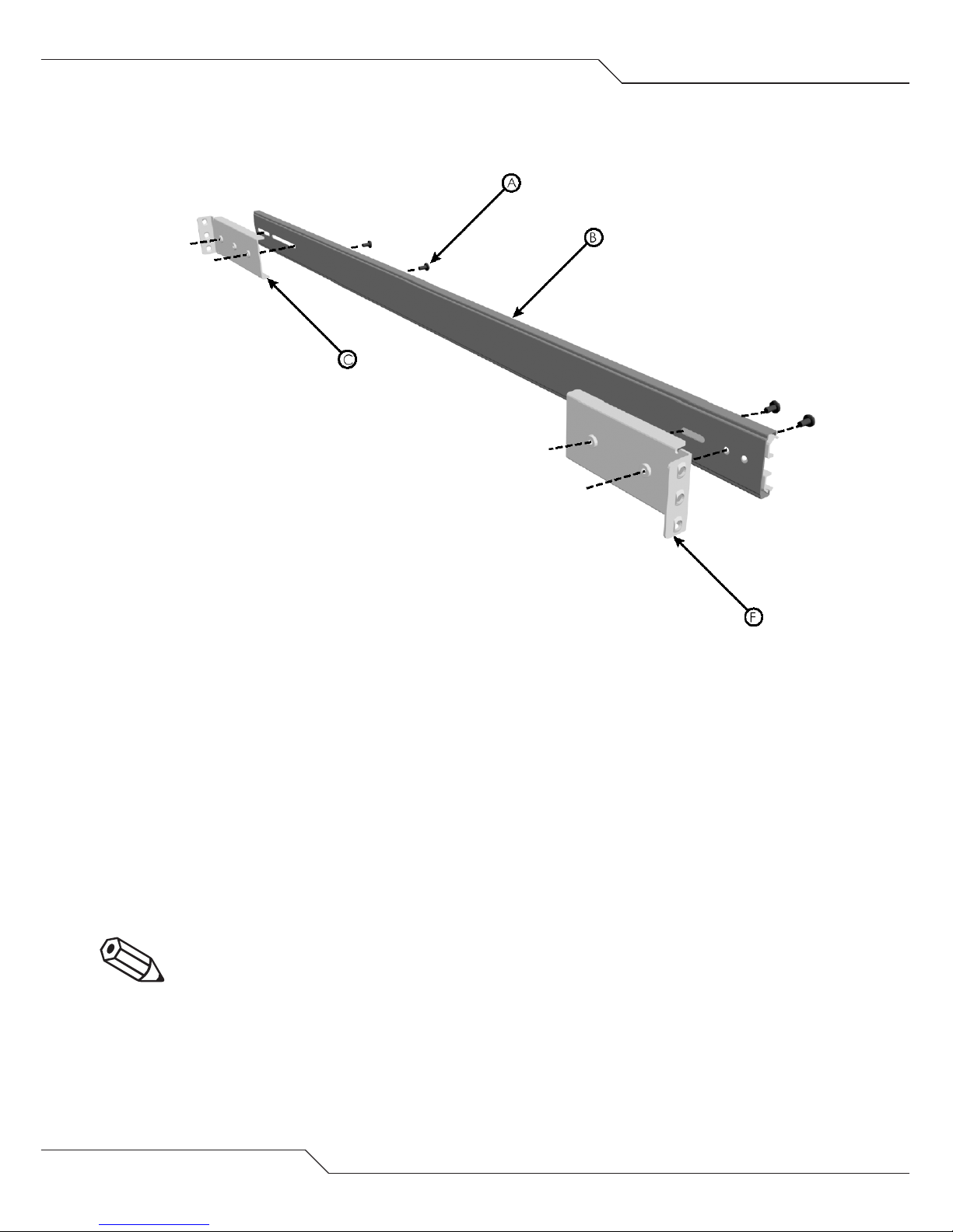
Inner Rack Slide Mounting Assembly
Left hand assembly shown
Parts List
[A] RACK EQUIPMENT – ATAbeast Chassis
[B] INNER SLIDE RAIL
[C] M4 x 6 SCREWS [ 8300038 ]

[w] www.nexsan.com
ATAbeast Product Manual
11
Instructions
-Remove chassis ears prior to rack mounting the equipment.
-Temporarily refit screws into chassis.
-Separate the inner rail from the intermediate / outer slide rail [B].
-Screw inner slide rail [B] to the side of the chassis using five
M4 x 6 screws.
-Repeat for right hand side.
-Ensure that the open end of the inner rack slide is situated toward
the rear of the chassis.
CAUTION: ALL REMOVABLE PARTS SHOULD BE REMOVED FROM
THE RACK EQUIPMENT PRIOR TO ASSEMBLY IN A RACK. i.e. PSU’s /
Controllers / Disks.
CAUTION: ENSURE THAT CORRECT LIFTING TECHNIQUES ARE USED
WHEN HANDLING RACK EQUIPMENT.
TOTAL OF BASE CHASSIS IS 24kg’s (33lbs)
12
ATAbeast Product Manual
[06.02] Rack Slide Mounting Bracket Assembly
Parts List
[A] M4 x 8 SLOTTED SCREW [ 8300047 ]
[B] SLIDE RAIL INTERMEDIATE / OUTER ASSEMBLY
[C] REAR MOUNTING BRACKET [ 3100331 ]
[D] FRONT MOUNTING BRACKET [ 3100330 ]
Instructions
-Attach front and rear [long] extended brackets [C and D] to the
outer rail using the diagram as a guide.
-Repeat for right hand slide rail.
NOTE: When attaching the rear brackets, first attach them loosely,
adjust the length to fit the cabinet and then tighten.

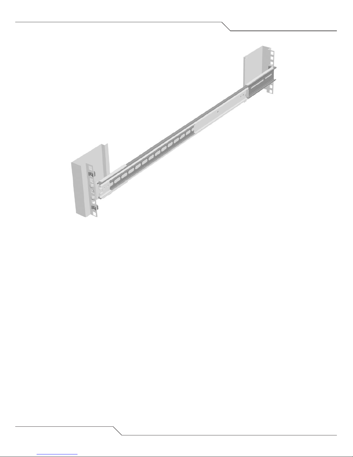
Mounting the Slide Assembly in a Rack
Left hand assembly shown
** the outer two cage nuts are used for securing the rack
enclosure once fitted.
[w] www.nexsan.com
ATAbeast Product Manual
13
[06.03]
Front rack mounting detail
14
ATAbeast Product Manual
Parts List
[A] OUTER SLIDE RAIL ASSEMBLY
[B] M5 FLANGED HEAD SCREW [ 8300098 ]
[C] M6 CAGE NUT [ 8300014 ]
[D] BAR NUT [ 3100080 ]
Left hand assembly shown

[w] www.nexsan.com
ATAbeast Product Manual
15
Instructions
-Check orientation of bar nut [ensure the near side of the bar nut
is facing the outside of the mounting brackets as shown].
-Press cage nuts into front rack flange holes [use the provided
paper template to locate correct fixing holes to position the
equipment in the rack].
-Sandwich the slide rail assembly between the inside flanges of the
rack and the bar nuts [C and D].
-Screw through both the rack flange and bar nuts with the M5
screw [B].
-Repeat on right hand side of rack
NOTE: The rear fixing of the slide rail assembly is identical to the
front fixing.
NOTE: Ensure that the outer slide rail assembly is aligned correctly
to accept the rack equipment you are mounting.
NOTE: Either Ensure that the rack slide assemblies are positioned
such that they are parallel to each other and vertical in relation to
the ground plane. Alternatively use the Installation alignment kit
3900062 purchased separately. Incorrect alignment or fitting of
rack slides may result in damage to the rack slides, the rack
equipment or injury to personnel.
NOTE: Prior to installation of the rack equipment loosely tighten
the fixing screws.

16
ATAbeast Product Manual
[06.04] Final Rack Equipment to Rack Assembly
Insertion view
Nexsan ATAbeast rack equipment shown
DO NOT ATTEMPT TO INSTALL THE ENCLOSURE WITH DISKS INSTALLED

[w] www.nexsan.com
ATAbeast Product Manual
17
Parts List
[A] ATAbeast RACK EQUIPMENT ASSEMBLY
[B] RACK ASSEMBLY
[C] M6 x 12 SCREWS [ 8300032 ]
Nexsan ATAbeast rack equipment shown
DO NOT ATTEMPT TO INSTALL THE ENCLOSURE WITH DISKS INSTALLED
Finished assembly

18
ATAbeast Product Manual
Instructions
-Carefully slide rack assembly [A] into the rack slide assemblies [B].
-Cycle this chassis in the slides a number of times to ensure free
movement prior to fully tightening the screws.
-Secure rack equipment into rack with four M6 x 12 screws [C]
after refitting rack ears [reverse of removal].
NOTE: Ensure intermediate slides are pushed all the way into the
outer slides and that the slide ball retainers are positioned at the
front of the intermediate slides prior to loading the rack equipment
NOTE: Do NOT over tighten screws, Over tightening screws could
damage your rack equipment.
NOTE: It is recommended that the equipment is installed by two
people to ensure correct alignment of the chassis in the rack.
CAUTION: ALL REMOVABLE PARTS SHOULD BE REMOVED FROM
THE RACK EQUIPMENT PRIOR TO ASSEMBLY IN A RACK.
CAUTION: ENSURE THAT CORRECT LIFTING TECHNIQUES ARE USED
WHEN HANDLING RACK EQUIPMENT.
CAUTION: ENSURE ALL RAIL SLIDE SCREWS ARE FULLY TIGHTENED
TO AVOID RACK EQUIPMENT FALLING OUT OF RACK.

[w] www.nexsan.com
ATAbeast Product Manual
19
[07.0] Inserting Disks
Physical Installation of disks
WARNING: POTENTIALLY HAZARDOUS ENERGY. TRAINED SERVICE
PERSONNEL ONLY.
1. Remove the 10 screws that are used to attach the front lid of
the product.
2. Remove the ATAbeast lid.

20
3. With the lid removed you are ready to insert the drives. Ensure
that you read pages 11 and 12 that displays the slot
arrangements for 14 and 28 drive systems and Dual Controller
Non Redundant systems. You must also use ESD protection
when installing drives to protect the disks from static discharge.
Lift up the disk with the interface ATA interface (pins) pointing
downward into the chassis. Line up the drive at the desired slot
and gently lower the drive until you meet resistance.
4. Firmly push the drive into the chassis until it reaches a full stop.
5. Repeat until all drives are installed. Reattach the lid and screw
into place before powering on the system.
ATAbeast Product Manual
Table of contents
Popular Storage manuals by other brands


Linn
Linn Kivor Tunboks Getting started guide

Fantec
Fantec QB-X8US3 Quick installation guide

Seagate
Seagate Enterprise Capacity 3.5 HDD/Constellation ES product manual

Western Digital
Western Digital Ultrastar Data60 installation guide

X-Micro
X-Micro Bluetooth USB Dongle user manual

Hitachi
Hitachi HUSSL4040BSS600 Quick installation guide


