For questions or additional information, see
the IBM 3581 Ultrium Tape Autoloader
Setup, Operator and Service Guide.
For the latest publications, visit the Web at
http://www.ibm.com/storage/lto
?
1
2
3
4
5
MODE
NEXT
SELECT
PREVIOUS
ALARM
ACTIVITY
POWER
POWER
67
11
12
1
2
3
9
9
4
4
5
5
10
10
6
7
8
8
Plug the power cord into the autoloader, and then plug the
other end into a properly grounded electrical outlet.
Install the SCSI terminator. The autoloader will not power on
correctly without a terminator.
Connect the SCSI cable between the host and the autoloader.
Open the front door and press the POWER button to power on
the autoloader. When the autoloader completes the Power-On
Self Tests, LdR REAdY appears in the message display.
Power on the host.
Place cartridges in slots 1 through 5. The LCD indicates that
slots 1 through 5 are loaded.
Press the MODE button until LOAd SLOT is displayed.
Press the SELECT button twice. The tape in slot 1 will move to
slot 6.
Repeat steps 7 and 8 to move the tape in slot 2 to slot 7.
Install additional data cartridges in slots 1 and 2. The LCD
indicates that slots 1 through 7 are loaded. Close the front door.
Refer to your host and application software manuals to
configure the autoloader for use.
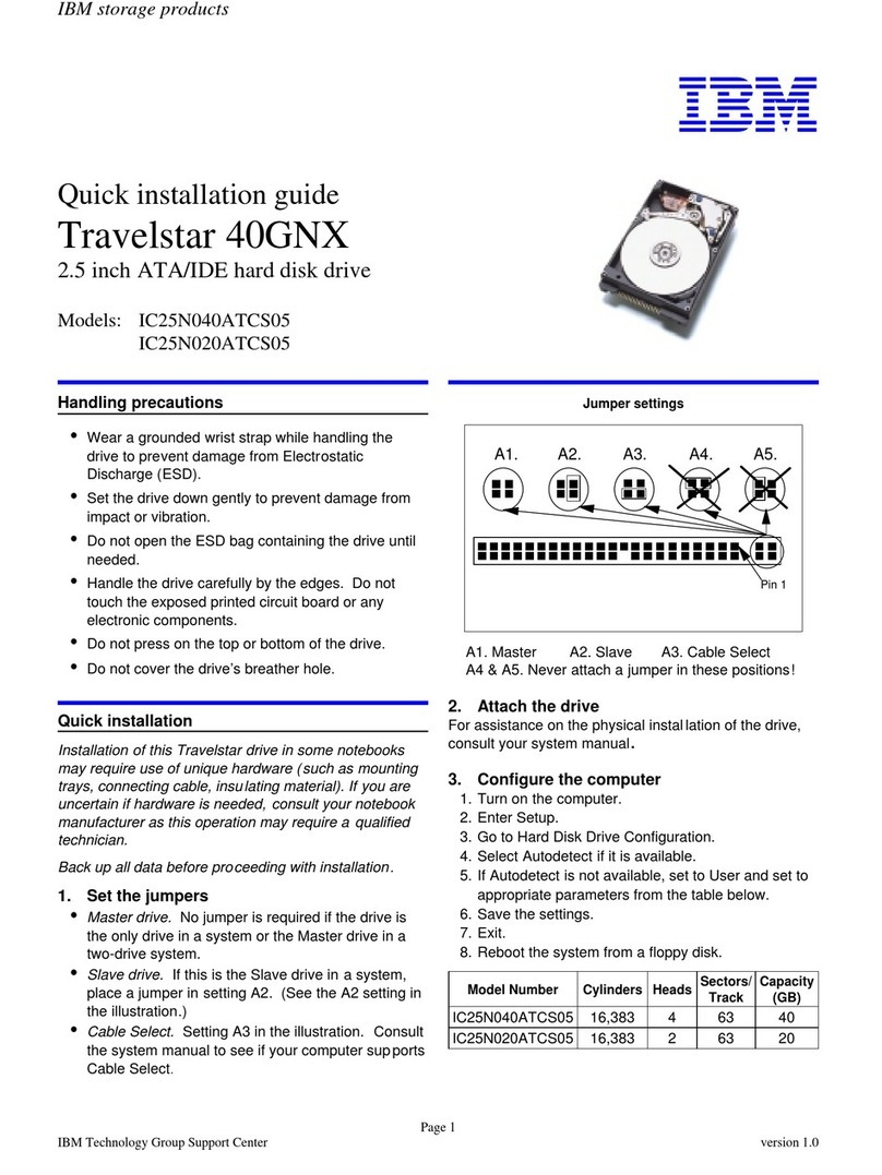
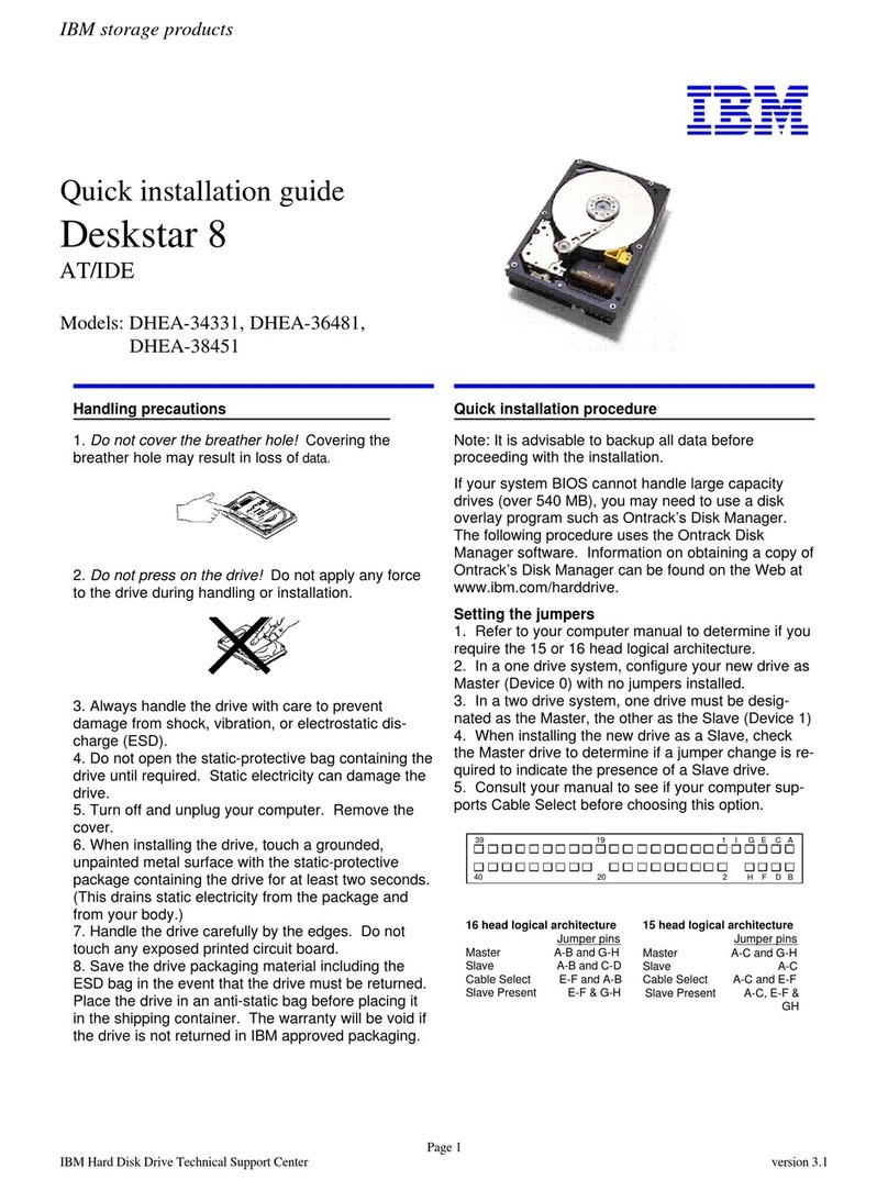
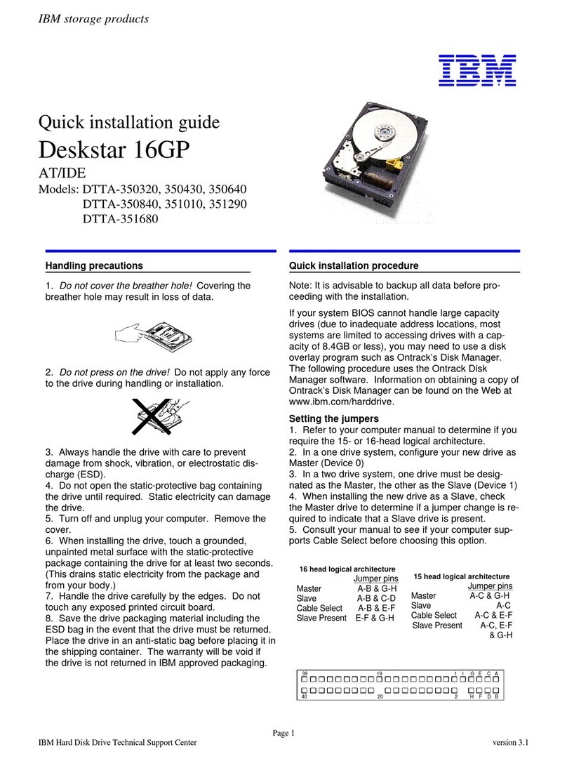
Note: The default settings for the SCSI IDs are 1 for the
autoloader and 3 for the drive.
Change the SCSI IDs for the autoloader and the drive, if
necessary. Repeatedly press the MODE button until SET SCSI
displays.
To skip setting the autoloader ID and set the drive ID, press
NEXT.
To set the autoloader ID, press SELECT. Press NEXT or
PREVIOUS until the SCSI ID that you want displays in LdR Id X
(X is the current ID). Press SELECT to accept the new ID, dRV
displays.
To set the drive ID press SELECT. Press NEXT or PREVIOUS
until the SCSI ID that you want displays in dRV Id X (X is the
current ID). Press SELECT to accept the new ID, CYCLE PWR
displays briefly.
Cycle power by pressing and holding the POWER button for
two seconds, wait a few seconds, and then press POWER
again. When the autoloader completes the Power-On Self
Tests, LdR REAdY appears in the message display. The new
SCSI IDs are now set.
Installation and Setup
Indicators and Controls
Controls
Press MODE to select operations or to
clear error conditions.
Press NEXT/PREVIOUS to view options
within a selected mode.
Press SELECT to execute an operation or
to move to the next menu level.
ALARM
ACTIVITY
POWER
LEDs
DC
CT
WP
LCD
Indicates the drive is in compressed mode
Indicates write-protected tape
Indicates cleaning tape is loaded or drive
cleaning is required
Indicates error condition
Indicates autoloader or drive activity
Indicates that power is on
MODE
NEXT
SELECT
PREVIOUS
ALARM
ACTIVITY
POWER
POWER
2
3
6
1
Single Autoloader on the SCSI Bus (Side View)
Multiple Devices on the SCSI Bus (Side View)
Autoloader
Host
SCSI Host Adapter Card
SCSI Connector
SCSI Bus Cable
Terminator
SCSI Connector
Autoloader
Another
Device
Host
SCSI Host Adapter Card SCSI Bus Cable
Terminator
SCSI Connector
SCSI Connector
Connecting the SCSI Bus Cable
7
11
12
