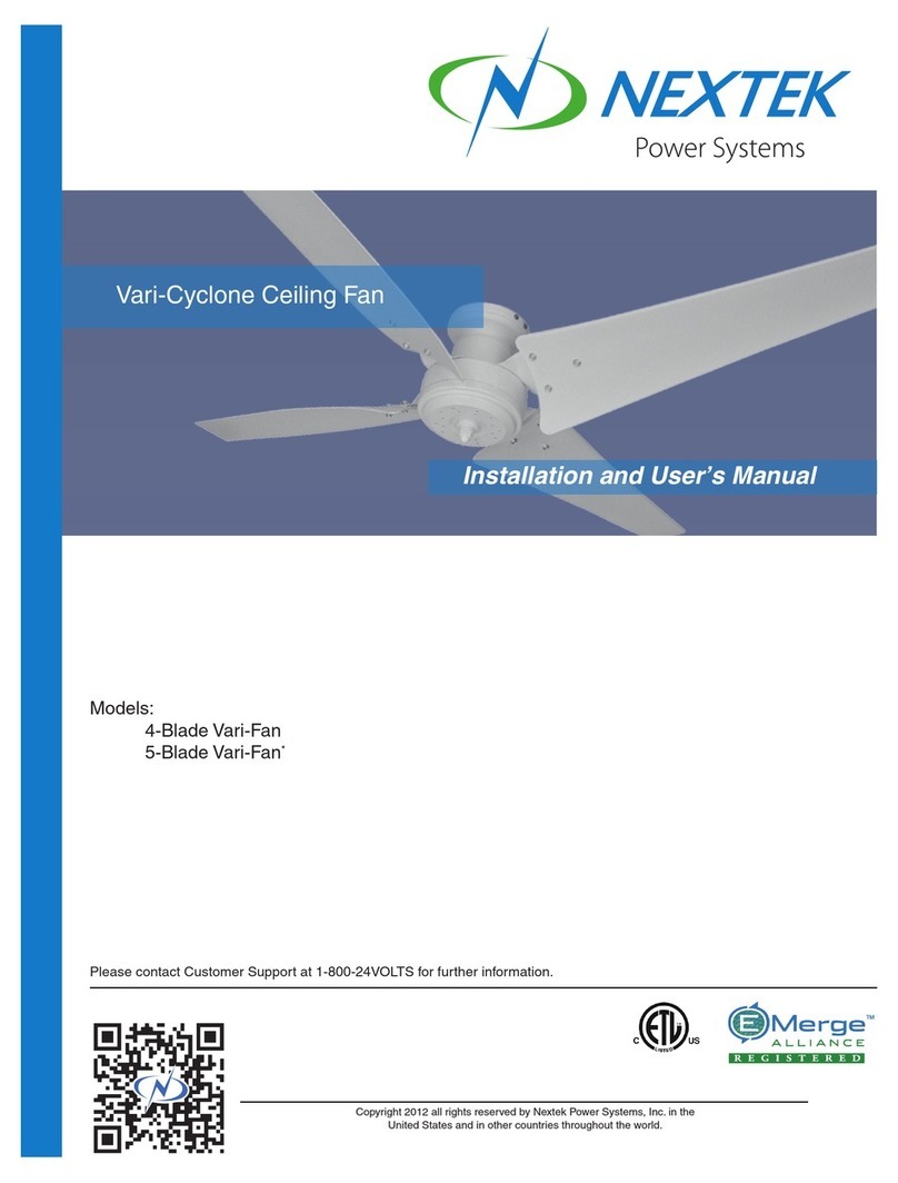
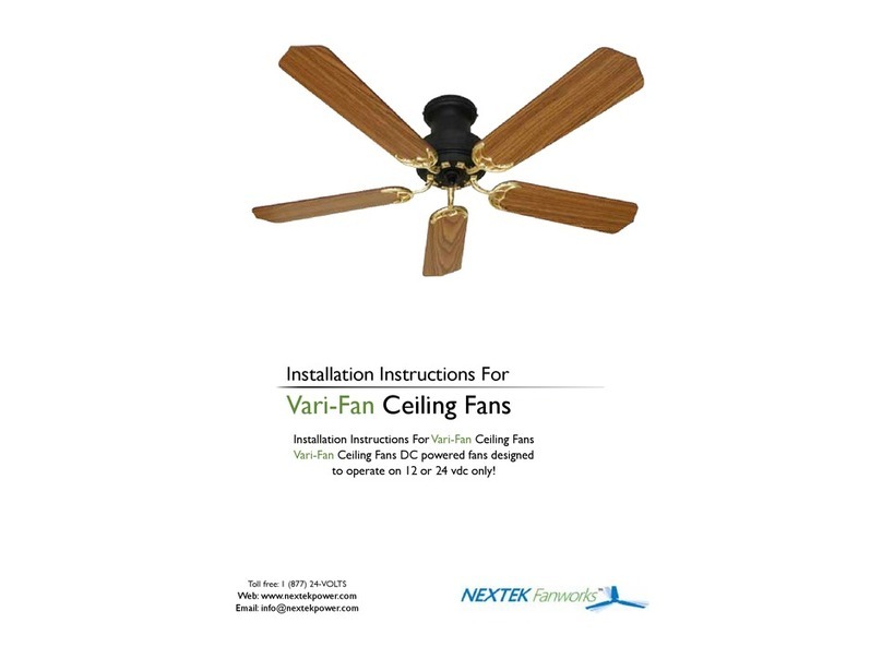
Nextek 4-Blade Vari-Fan User manual

Models:
4-Blade Vari-Fan
5-Blade Vari-Fan*
Rev 010713
Please contact Customer Support at 1-800-24VOLTS for further information.
Vari-Fan Ceiling Fan
Installation and Userʼs Manual
Copyright 2013 all rights reserved by Nextek Power Systems, Inc. in the
United States and in other countries throughout the world.

ABOUT NEXTEK POWER SYSTEMS 3
PRODUCT INTRODUCTION 4
1.0 SAFETY 5
2.0 STANDARDS & REQUIREMENTS 6
3.0 INSTALLATION QUALIFICATIONS 6
4.0 SPECIFICATIONS 7
5.0 NOTES AND WARNIN S 8
6.0 PARTS INFORMATION 9
7.0 INSTALLATION PROCEDURE 10
7.1 Pre-Installation Instructions 10
7.2 Inspection of Fan 10
7.3 Installation of Outlet Box and Rough-In Wiring 10
7.4 Fan Assembly Close Mount Version 11
7.5 Fan Assembly Down Rod Version 13
8.0 PAINTIN INSTRUCTIONS 15
9.0 START UP INFORMATION 16
10.0 TROUBLESHOOTIN 17
Rev. 010713
TABLE OF CONTENTS
For more information: Nextek Power Systems Tel: 313-887-1321 www.nextekpower.com
461 Burroughs Street Toll free: 1 (877) 24-VOLTS
Detroit, Michigan 48202 Fax: 313-887-9433 info@nextekpower.com
2 Copyright 2013 all rights reserved by Nextek Power Systems, Inc. in the United States and in other countries throughout the world.
Models: 4/5-Blade Vari-Fan
Vari-Fan Ceiling Fan Installation Manual

Nextek Power Systems AC/DC integration technology represents a breakthrough in on-
site electrical management, combining the availability of AC power with the quality and
efficiency of a DC supply.
NEXTEK PRODUCT BENEFITS
•Easy conversion of AC lighting fixtures to DC-powered units
•Easy conversion of AC grid power into DC power for commercial building
applications
•Highly efficient management of peak loads
•Future-proof lighting and other systems to be developed
•Nextek Power Systems Direct Coupling® Technology, directly connects clean
power generated at a building to its electronic loads inside cutting down on over-
all power consumption, boosts electricity generated and stored on-site, and
delivers a robust renewable energy ready network.
DISCLAIMER
Nextek Power Systems has made every reasonable effort to ensure the accuracy of the
information in this catalog. Nextek Power Systems does not guarantee that the
information is error free, nor do we make any other representation, warranty or
guarantee that the information is accurate, correct, reliable or current. Nextek Power
Systems, Inc. reserves the right to make any adjustments to the information contained
herein at any time without notice. The specifications in this catalog are for reference
purposes only and are subject to change without notice. Consult Nextek Power Systems
for the latest design specifications. All trademarks are either the exclusive property of
Nextek Power Systems, Inc. or other companies. Copyright © 2013 by Nextek Power
Systems, Inc. in the United States and other countries throughout the world.
ABOUT NEXTEK POWE SYSTEMS
Rev. 010713
Copyright 2013 all rights reserved by Nextek Power Systems, Inc. in the United States and in other countries throughout the world. 3
Models: 4/5-Blade Vari-Fan
Vari-Fan Ceiling Fan Installation Manual

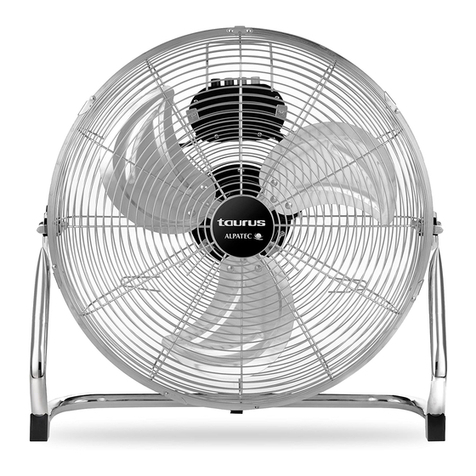
Nextek Vari-Fan DC Powered Ceiling Fans
Features:
• Can be mounted 10” to 48” from ceiling (4”
down rod included, custom rods can be
made)
• Can be assembled with either 4 or 5
blades
• Body is black, but comes with instructions
for easy painting
• Body parts are made from injection
molded, glass filled ABS plastic
• Blade arms are cast metal with a polished brass finish
• Blades are laminated with a light faux wood finish on one side and a dark faux wood
finish on the other side
The Vari-Fan DC Powered Ceiling Fan is the perfect choice for a variety of
indoor/outdoor applications, including homes, enclosed porches, greenhouses,
warehouses, offices, schools and cabins. Everything you need to assemble and mount
a 4- or 5-blade Vari-Fan comes right in the box.
The Vari-Fan is powered by a permanent magnet, TENV (totally enclosed non-
ventilated) motor with long life brushes. The motor draws 0.5 amps at 12 VDC and 0.78
amps at 24 VDC. At 12 VDC the 5-blade fan will run at approximately 60 rpm, moving
1,500 CFM when mounted at least 8 feet above the floor in an open room. At 24 VDC
the 5-blade fan will run at approximately 120 rpm, moving 2,700 CFM when mounted at
least 8 feet above the floor in an open room.
For maximum efficiency use the Nextek Power Systems Speed Control in conjunction
with the Vari-Fan DC Powered Ceiling Fans. The Speed Control makes clockwise and
counter-clockwise rotation possible.
P ODUCT INT ODUCTION
Rev. 010713
4 Copyright 2013 all rights reserved by Nextek Power Systems, Inc. in the United States and in other countries throughout the world.
Models: 4/5-Blade Vari-Fan
Vari-Fan Ceiling Fan Installation Manual

1.1 SAVE THESE INSTRUCTIONS– This manual contains important safety and
operating instructions for the Nextek Vari-Fan Ceiling Fan.
The following symbols are used throughout this manual to indicate potentially
dangerous conditions or mark important safety instructions:
DANGE :
Indicates an imminently hazardous situation which, if not avoided, will
result in death or serious injury.
WA NING:
Indicates a potentially dangerous condition. Use extreme caution when
performing this task.
CAUTION:
Indicates a critical procedure for safe and proper operation of the
controller.
NOTE:
Indicates a procedure or function that is important for the safe and
proper operation of the controller.
1.2 Before using the fan, read all instructions and cautionary markings.
1.3 Electrical hazards are probably the most common hazards throughout the
industry. Virtually all workplaces have electrical installations and use electricity.
1.4 It is very important that all industry employees be familiar with electrical hazards
and know how to protect themselves when working on, near, or with electricity.
In most cases, industry electrical and electronic equipment is designed for both
maximum safety and efficiency. However, potentially hazardous conditions such
as inadvertent contact with hazardous voltages may exist while performing
servicing and maintenance, handling materials, or cleaning.
1.5 The improper use of electrical extension cords and portable electrical
equipment can result in hazardous exposure.
1.6 WA NING - ISK OF ELECT ICAL SHOCK
Read all of the instructions and cautions in the manual before beginning
installation.
1.7 DANGE – TO EDUCE THE ISK OF FI E O ELECT IC
SHOCK, CA EFULLY FOLLOW THESE INST UCTIONS
Rev. 010713
1.0 SAFETY
Copyright 2013 all rights reserved by Nextek Power Systems, Inc. in the United States and in other countries throughout the world. 5
Models: 4/5-Blade Vari-Fan
Vari-Fan Ceiling Fan Installation Manual

1.7.1 Do not disassemble or attempt to repair the fan other than the
troubleshooting procedures listed in this manual.
1.7.2 Disconnect power to the unit before installing, removing, cleaning or
otherwise maintaining the unit.
1.8 INSTALLATION SAFETY PRECAUTIONS
1.8.1 Mount the fan indoors. Prevent exposure to the elements and do not
allow water to enter the fan.
1.8.2 The Vari-Fan is to be connected to DC circuits only
2.0 STANDA DS AND EQUI EMENTS
2.1 All DC cable types must meet all local and national codes
2.2 Shut off all DC circuit breakers or fuses before installing any unit into the field
3.0 INSTALLATION QUALIFICATIONS
3.1 Installation work and electrical wiring of permanently-connected power units
must be performed only by qualified service personnel in accordance with all
applicable codes and standards, including fire-rated construction.
Rev. 010713
1.0 SAFETY
6 Copyright 2013 all rights reserved by Nextek Power Systems, Inc. in the United States and in other countries throughout the world.
Models: 4/5-Blade Vari-Fan
Vari-Fan Ceiling Fan Installation Manual

Rev. 010713
4.0 SPECIFICATIONS
Copyright 2013 all rights reserved by Nextek Power Systems, Inc. in the United States and in other countries throughout the world. 7
Models: 4/5-Blade Vari-Fan
Vari-Fan Ceiling Fan Installation Manual
For maximum efficiency use 20-Watt Solar Panel and the Nextek Power Systems Speed Control
in conjunction with the Vari-Fan DC Powered Ceiling Fans. The Speed Control makes clockwise
and counter-clockwise rotation possible.
The Vari-Fan is powered by a permanent magnet, TENV (totally enclosed non-ventilated) motor with long
life brushes. The motor draws 0.5 amps at 12 VDC and 0.78 amps at 24 VDC. At 12 VDC the 5-blade fan
will run at approximately 60 rpm, moving 1,500 CFM when mounted at least 8 feet above the floor in an
open room. At 24 VDC the 5-blade fan will run at approximately 120 rpm, moving 2,700 CFM when
mounted at least 8 feet above the floor in an open room.
20 WATT SOLA PANEL:
These panels are glass laminated with aluminum frames with junction boxes on the back.
Peak power (watts) 20 Peak power (volts) 17.3 Peak power (amps) 1.2 Nominal voltage 21.7
Length: 24.4 inches (62.1cm) Width: 11.1 inches (28.2cm) Weight: 5.5 lbs. (2.5kg) Shipping weight: 8.5 lbs. (4.2kg)
SPEED CONTROL:
This unit provides an adjustable 12 to 30 VDC from an input of 11 to 24 VDC. It has a voltage
control POT with an On\Off switch to change the fan’s direction. It is overload protected by input
and output self resetting fuses. This unit will fit in a single gang electrical box.
4/5-Blade Vari-Fan
MECHANICAL
Diameter of blade swing 42 inches (1.07 m)
Weight of fan 11 lbs. (4.99 kg)
Shipping weight 12 lbs. (5.44 kg)
ELECTRICAL
Amps 0.5 @ 12 VDC
0.78 @ 24 VDC
RPM 60 @ 12 VDC
120 @ 24 VDC
CFM 1,500 @ 12 VDC
2,700 @ 24 VDC

Rev. 010713
8 Copyright 2013 all rights reserved by Nextek Power Systems, Inc. in the United States and in other countries throughout the world.
Models: 4/5-Blade Vari-Fan
Vari-Fan Ceiling Fan Installation Manual
5.0 NOTES AND WA NINGS
5.1 NOTES:
5.1.1 It is recommended that all Nextek Fanworks DC ceiling fans be used in
conjunction with the Nextek 12/24V Speed Controller.
5.1.2 If operating in a 12V environment, the 12/24V speed control is required.
5.1.3 The Nextek DC ceiling fans can be operated above 24VDC, but not to
exceed 48VDC. A 48VDC Speed Controller can be special ordered. The
12/24V speed control is designed to work only between 12V and 24V.
5.1.4 A Nextek 12.6 watt solar panel is available and perfectly matched for this
DC powered ceiling fan and speed control.
5.1.5 For new installations: This is a low-voltage 12/24V DC-powered device.
Appropriate sizing of a solar panel, battery and battery charge controller
are essential for proper operation. Consult a qualified installer of DC
devices to insure correct configuration.
5.1.6 For installation in existing DC power environment: reat care must be
taken to ensure fan is wired properly in existing DC power environment.
Warranty may be violated if attempting to operate in anything other than
12/24V DC. Please consult a qualified technician.
5.1.7 Failure to wire correctly or install in a non-recommended power
environment may violate your warranty.
5.2 WA NINGS:
5.2.1 To reduce the risk of fire or electrical shock use Nextek 12/24V speed
controls only.
5.2.2 To reduce the risk of personal injury, do not bend the blade brackets
when installing the brackets or cleaning the fan. Do not insert foreign
objects in between rotating fan blades.
5.2.3 To reduce the risk of personal injury, install the fan only to the building
structure according to these instructions, and use only the hardware
supplied.
5.3 CAUTIONS:
5.3.1 Read entire instructions carefully before beginning installation.
5.3.2 To avoid possible electrical shock, be certain electricity is shut off at main
panel before wiring.
5.3.3 All wiring must be in accordance with national and local electrical codes.
If you are unfamiliar with wiring, you should use a qualified electrician.

6.0 PA TS INFO MATION
Rev. 010713
Copyright 2013 all rights reserved by Nextek Power Systems, Inc. in the United States and in other countries throughout the world. 9
6.1 Parts List
01 1 x Mounting Bracket
02 4 x 10/32 x 3/8 P.H. Phillips
03 1 x Mounting cone
04 4 x 10/32 x 3/8” P.H.Phillips
05 1 x Pivot Ball
06 1 x Retaining Pin
07 1 x Down Rod
08 1 x Pin & Clip
09 1 x 10/32 x 3/8 P.H. Phillips
10 4 x 8/32 x 1/2 F.H. Phillips
11 1 x Receptacle
12 1 x Motor Housing
13 1 x Fan Motor
14 1 x Hub
15 1 x 1/4 /20 x 5/16 Set Screw
16 10 x 10/32 x 3/8 P.H. Phillips
17 1 x Retaining Clip
18 1 x Retaining Knob
19 15 x 10/32 x 1/2 P.H. Phillips
20 15 x Washers
21 5 x Fan Blades
22 5 x Blade Arms
Models: 4/5-Blade Vari-Fan
Vari-Fan Ceiling Fan Installation Manual

Rev. 010713
10 Copyright 2013 all rights reserved by Nextek Power Systems, Inc. in the United States and in other countries throughout the world.
7.0 INSTALLATION P OCEDU E
7.1 Pre-Installation Instructions
7.1.1 Select installation site. Check to see that in normal use no object can
come in contact with the rotating fan blades. The mounting site should
also meet the precautions listed in Step 7.3 below.
7.1.2 Installation hardware is included for a standard drywall or plaster ceiling.
You will need a 4" x 1-1/2" or a 4" x 1/2" outlet box and wire nuts (2),
which can be purchased from any hardware store or electrical supply
house.
7.1.3 The fan blades must be mounted
at least 7' above the floor. For
maximum efficiency, they should
not have any obstruction (walls,
posts, etc.) within 24" of the blade
tips. See Figure 1 for mounting
distances.
7.2 Inspection of Fan
7.2.1 Unpack the fan carefully to avoid any damage to the components.
7.2.2 Check for any shipping damage to the motor and the fan blades. If more
than one fan is being installed, keep the matched and balanced fan
blades in sets, as they were shipped. Should one of the fan blades
become damaged during shipment, return all blades in the set for
replacement.
7.2.3 Check contents to be certain it contains a bag of parts.
7.3 Installation of Outlet Box and ough-In Wiring
CAUTIONS:
Your ceiling fan, when operating, can have a weight plus downdraft of up
to 35 lbs. The following precautions must be taken for safety and to
ensure that your fan is securely mounted to the ceiling.
Be certain electricity is “off” at fuse panel when inspecting or repairing
installation site.
All wiring must meet local and national electrical codes.
Do not mount directly to an unsupported ceiling or to an electrical outlet
box. Mounting must support a total weight of 35 lbs.
Models: 4/5-Blade Vari-Fan
Vari-Fan Ceiling Fan Installation Manual

7.3.1 Secure metallic outlet box 4" x 1-1/2" or
4" x 1/2" deep to 2 x 4 cross brace
between two ceiling joists as shown in
Figure 2. The outlet box must be
recessed into the ceiling by 1/16”
minimum. Secure the outlet box to the
cross brace by drilling (2) pilot holes no
larger than the minor diameter of the
wood screws (5/64") and use two #8 x 1-1/2" wood screws and washers.
Use the innermost holes for securing the box. Orient the box so the
outermost holes will be used in Step 4B.
CAUTION:
Do not use a lubricant on screws.
7.3.2 Bring electrical cable into the outlet.
Make certain that wiring motor assembly
meets all national and local electrical
codes. Wire leads should extend at least
6" beyond outlet box for ease in making
connections. See Figure 3.
7.4 Fan Assembly Close Mount Version
7.4.1 Remove mounting bracket (#1) from mounting cone (#3).
Leave the screws in the bracket that match up with the open
hole on each side of mounting cone.
7.4.2 Attach mounting bracket to junction box or
directly to ceiling using screws taped to
mounting bracket. Lead wires through
center hole in bracket.
7.4.3 Remove retaining knob (#18) and clip (#17) from bag found
inside hub (#14).
7.4.4 Align the hub (#14) with the motor shaft (#13).
Align the flat side of the motor shaft to the allen
screw hole. Push hub onto shaft until 3/8” (1cm)
of the shaft protrudes from the hub. Tighten set
screw using allen wrench included with fan.
NOTE: To prevent wobble, make sure the FLAT of the motor shaft is
aligned with the FLAT of the center of hub. The set screw should be
tightened against the center of the FLAT of the motor shaft.
Rev. 010713
7.0 INSTALLATION P OCEDU E
Copyright 2013 all rights reserved by Nextek Power Systems, Inc. in the United States and in other countries throughout the world. 11
Models: 4/5-Blade Vari-Fan
Vari-Fan Ceiling Fan Installation Manual

7.4.5 Push retaining clip (#17) onto motor shaft unit until it is firmly
against the hub.
WA NING: Failure to install the retain clip tightly against the
hub as described may cause separation of the hub during fan operation.
Serious injury may result. Consult a qualified installer if in any doubt
about installation procedures.
7.4.6 Push retaining knob (#18) onto motor shaft until it is firmly
against the hub.
7.4.7 Lift completed motor and hub assembly to
mounting bracket on ceiling, and slip one hole on
side of mounting cone over hook on bracket.
7.4.8 With motor and assembly hanging from hook, connect fan wires to the
house wires using three (3) wire nuts included with fan. Connect white
wire of fan to the negative power house wire and the black wire of the fan
to the positive power house wire. The green wire should be connected to
the ground wire on the mounting bracket. Fan should operate in a
counter-clockwise direction for downward draw (summer). For upward
draw (winter), use the reverse button on the Speed Controller.
7.4.9 After wires are connected, remove fan from hook, and slip
mounting cone over mounting bracket. Align the open
holes of cone with the two screws, and rotate until cone
will stay in place. Then replace the other two screws in cone and tighten
all four screws firmly.
7.4.10 Turn on power, and check that motor shaft is turning in a counter
clockwise direction. Turn power off.
7.4.11 Assemble blade arm (#22) and fan blades (#21) using the 15
screws and washers (#20) that are in bag with blade arms.
7.4.12 Once the blades and arms are assembled,
attach the assemblies to the hub using the bag
of 10 screws (#16). The inside hole pattern on
the hub is for four (4) blades. The outside hole
pattern on the hub is for five (5) blades.
7.4.13 Turn on your fan
12 Copyright 2013 all rights reserved by Nextek Power Systems, Inc. in the United States and in other countries throughout the world.
Vari-Fan Ceiling Fan Installation Manual
Models: 4/5-Blade Vari-Fan
Rev. 010713
7.0 INSTALLATION P OCEDU E

7.5 Fan Assembly Down od Version
7.5.1 Remove mounting bracket (#1) from mounting cone. (#3)
Leave the screws in the bracket that match up with the open
hole on each side of mounting cone.
7.5.2 Attach mounting bracket to junction box or
directly to ceiling using screws taped to
mounting bracket. Lead wires through center
hole in bracket.
7.5.3 Remove the four screws (#04) holding the
mounting cone (#3) to top of fan. Remove cone
from top of fan.
7.5.4 Put down rod (#07) through mount cone (pivot
ball (#05) end of rod remains in cone).
7.5.5 Feed wires from receptacle through bottom of
down rod (#07) and out through the pivot ball
end.
7.5.6 Remove retaining pin and retaining clip (#08)
from receptacle.
7.5.7 Slip down rod into receptacle, and align holes of rod with hole in
receptacle.
7.5.8 Re-insert pin through receptacle/down rod assembly and attach clip.
7.5.9 Tighten screw on side of receptacle.
7.5.10 Align the hub (#14) with the motor shaft (#13). Align the flat
side of the motor shaft to the allen screw hole.
Push hub onto shaft until 3/8" (1cm) of the
shaft protrudes from the hub. Tighten set screw
using allen wrench included with fan.
NOTE: To prevent wobble, make sure the FLAT of the motor shaft is
aligned with the FLAT of the center of hub. The set screw should be
tightened against the center of the FLAT of the motor shaft.
7.5.11 Push retaining clip (#17) onto motor shaft unit until it is firmly
against the hub.
WA NING: Failure to install the retain clip tightly against the hub as
described may cause separation of the hub during fan operation. Serious
injury may result. Consult a qualified installer if in any doubt about
installation procedures.
Copyright 2013 all rights reserved by Nextek Power Systems, Inc. in the United States and in other countries throughout the world. 13
Vari-Fan Ceiling Fan Installation Manual
Models: 4/5-Blade Vari-Fan
Rev. 010713
7.0 INSTALLATION P OCEDU E

7.5.12 Push retaining knob (#18) onto motor shaft until it is firmly
against the hub.
7.5.13 Lift completed motor and hub assembly to
mounting bracket on ceiling, and slip one hole
on side of mounting cone over hook on bracket.
7.5.14 With motor and assembly hanging from hook,
connect fan wires to the house wires using three (3) wire nuts included
with fan. Fan should only be operated in a counter-clockwise direction.
Connect white wire of fan to the negative power house wire and the black
wire of the fan to the positive power house wire. The green wire should
be connected to the ground wire on the mounting bracket.
7.5.15 After wires are connected, remove fan from hook, and
slip mounting cone over mounting bracket. Align the
open holes of cone with the two screws, and rotate until
cone will stay in place. Then replace the other two
screws in cone and tighten all four screws firmly.
7.5.16 Turn on power, and check that motor shaft is turning in a counter
clockwise direction. Turn power off.
7.5.17 Assemble blade arm (#22) and fan blades (#21) using the
15 screws and washers (#20) that are in bag with blade
arms.
7.5.18 Once the blades and arms are
assembled, attach the assemblies to the
hub using the bag of 10 screws (#16). The
inside hole pattern on the hub is for four
(4) blades. The outside hole pattern on the
hub is for five (5) blades.
7.5.19 Turn on your fan.
14 Copyright 2013 all rights reserved by Nextek Power Systems, Inc. in the United States and in other countries throughout the world.
Vari-Fan Ceiling Fan Installation Manual
Models: 4/5-Blade Vari-Fan
Rev. 010713
7.0 INSTALLATION P OCEDU E

8.1 Painting
8.1.1 The Vari-Fan can be easily painted using an acrylic based spray paint.
8.1.2 Dark colors (red, blue, green, or brown) should take only one coat of
paint.
8.1.3 Light colors (white, yellow, or pastels) may take two or more coats. Follow
the instructions on the can of spray paint for applying multiple coats.
8.1.4 To disassemble the Vari-Fan, look at the exploded drawing in Parts
Information (6.0). This will show you how the fan comes apart. Be sure to
use a bag or cup for storing screws and pins.
8.1.5 There are four (4) parts that are normally painted: the mounting cone
(part #03), the down rod (part #07), motor housing (part #12), and the
hub (part #14). Be sure to remove the set screw from the hub.
8.1.6 The receptacle (part #11) and the pivot ball (part #5) are normally left
black.
8.1.7 Using soft wire, make 4 long “S” hooks so each piece may be hung while
painting and drying.
8.1.8 Follow the instructions on your can of spray paint for proper spraying
technique and drying times required.
8.1.9 Once the painted parts are dry, you may re-assemble the fan following
the diagram in Parts Information.
Copyright 2013 all rights reserved by Nextek Power Systems, Inc. in the United States and in other countries throughout the world. 15
Vari-Fan Ceiling Fan Installation Manual
Models: 4/5-Blade Vari-Fan
Rev. 010713
8.0 PAINTING

9.1 Start Up Procedures
9.1.1 All Nextek Fanworks DC-powered ceiling fans should be used in
conjunction with the Nextek 12/24V Speed Controller.
9.1.2 If operating in a 12V environment, the 12/24V Speed
Controller is required.
9.1.3 All Nextek Fanworks DC-powered ceiling fans can be
operated above 24VDC, but not to exceed 48VDC. A 48VDC
Speed Controller can be ordered.
9.1.4 A Nextek 12.6 watt solar panel is available and is perfectly matched to
this DC-powered ceiling fan and Speed Controller.
9.1.5 New Installations: Appropriate sizing of a solar panel, battery and battery
charge controller are essential for proper operation. Consult a qualified
installer of DC devices to ensure correct configuration.
9.1.6 Existing Environments: reat care must be taken to ensure fan is wired
properly in existing DC power environments. Warranty may be violated if
attempting to operate in anything other than 12/24 VDC. Please consult a
qualified technician.
9.1.7 Failure to wire correctly, or installation in non-recommended power
environments may violate your warranty.
CAUTION
9.2.1 Read the entire ceiling fan instruction manual carefully before beginning
installation. (See above for download location.)
9.2.2 To avoid possible electric shock, be certain electricity is shut off at main
panel before wiring.
9.2.3 All wiring must be in accordance with national and local electrical codes.
If you are unfamiliar with wiring, you should use a qualified electrician.
16 Copyright 2013 all rights reserved by Nextek Power Systems, Inc. in the United States and in other countries throughout the world.
Vari-Fan Ceiling Fan Installation Manual
Models: 4/5-Blade Vari-Fan
Rev. 010713
9.0 STA T UP P OCEDU E

Copyright 2013 all rights reserved by Nextek Power Systems, Inc. in the United States and in other countries throughout the world. 17
Vari-Fan Ceiling Fan Installation Manual
Models: 4/5-Blade Vari-Fan
Rev. 010713
10.0 T OUBLESHOOTING
The following are tips that may help fix a problem that you are having with a Nextek
Power Systems Fanworks DC powered ceiling fan.
P OBLEM P OCEDU E
FAN DOESN’T RUN Check all connections to make sure you have power, use a volt meter or
multi tester to confirm that the voltage is correct. If fan still doesn’t run, try
connecting the fans leads directly to the battery (no switches or speed
controls) If fan still won’t run, please contact Nextek Power Systems
Fanworks, not your dealer.
FAN MOTOR IS HOT TO
THE TOUCH
Turn off fan immediately, and contact Nextek Power Systems Fanworks.
FAN MAKES “CLICKIN ”
NOISE
The “clicking” noise is usually a bur on one or both brushes. First try
reversing the fan (i.e.: make it run backwards) this can be done by reversing
the polarity of the fans wires at the battery. If your fan has a speed control
but no reversing switch, reverse the leads that run from the speed control to
the fan. In either case, let the fan run at least 24 hours in reverse, then try
running the fan in forward and see if the noise stops.
A second option, if your fan is not too high up, is to take a broom handle
and give a sharp upward rap to the decorative nut at the center of the fan
hub. (Do this while the fan is running)
Please note: Fans in summer cottages or in places where the fan is not run
for long periods of time are more prone to developing a burr on the brushes.
Before starting fan, gently spin the blades by hand, and then turn on fan.
If problem persists, please contact Nextek Power Systems Fanworks.
MY FAN WOBBLES
WHEN RUNNIN
Most fans mounted with a down rod will have a slight wobble (less than 1
inch from the center) depending on how long the down rod is.
All Nextek Power Systems Fanworks fans come from the factory with
balanced blades and blade arms.
Make sure that the when the hub was placed on the fan shaft, the flat on
the shaft matched the flat on the hub’s center hole.
Check that all the blade arms have the same pitch. (Lay them in line on a
flat surface and check that all the blade arms lay at the same angle.) If the
pitch on one of the blade arms is different, try twisting the arm until it
matches the rest of the arms.
Most large hardware stores—Home Depot, Lowes, Ace, etc, that sell ceiling
fans—have blade balancing kits. These are inexpensive and have easy-to-
understand instructions, and may be an alternative if the above ideas don’t
work.

18 Copyright 2013 all rights reserved by Nextek Power Systems, Inc. in the United States and in other countries throughout the world.
Vari-Fan Ceiling Fan Installation Manual
Models: 4/5-Blade Vari-Fan
Rev. 010713
P OBLEM P OCEDU E
MY FAN MAKES A
RUBBIN SOUND WHEN
RUNNIN
Turn your fan off, and when the blades have stopped turning, spin the fan
with your hand, if you hear the rubbing sound, it is most likely that the fan’s
hub is rubbing against the motor housing.
Loosen the hub’s set screw; remove the decorative knob covering the fan’s
motor shaft. Using a flat bladed screwdriver, pry the safety push nut away
from the hub (about 1/8 inch) Try spinning the fan again, if the rubbing
sound is gone, then re-tighten the set screw and replace the decorative
knob.
MY FAN’S BLADES
SEEM TO O UP AND
DOWN AS THE FAN
SPINS
Turn fan off, gently rotate hub by hand, look for the high and low movement
of the blades. rab the hub at the high spot with one hand, with your other
hand, grab the low spot, then “gently” push the low side of the hub up while
pulling down on the high side. Spin the hub again and see if the up/down
wobble is gone, if not, repeat the procedure until problem is fixed.
10.0 T OUBLESHOOTING

For more information: Nextek Power Systems Tel: 313-887-1321
461 Burroughs Street Toll free: 1 (877) 24-VOLTS
Detroit, Michigan 48202 Fax: 313-887-9433
www.nextekpower.com info@nextekpower.com
Other manuals for 4-Blade Vari-Fan
2
This manual suits for next models
1
Table of contents
Other Nextek Fan manuals
