Aprilaire 8145A User manual

1
READ AND SAVE THESE INSTRUCTIONS
VENTILATION CONTROLLER
FILTER COVER
LOW PRESSURE PORT
LOW PRESSURE PORT
HIGH PRESSURE PORT
HIGH PRESSURE PORT
INLET COLLAR AND
NORMALLY CLOSED
POWER DAMPER
INLET COLLAR AND
NORMALLY CLOSED
POWER DAMPER
OUTLET COLLAR
OUTLET COLLAR
SURFACE MOUNT
BRACKET LOCATION
JOIST MOUNT
BRACKET LOCATION
INSTALLATION & OPERATING
INSTRUCTIONS
Model 8145A
Fresh Air VentilatorVentilation

2
SAFETY INSTRUCTIONS
WARNING
1. 120 Volts may cause serious injury from electric shock. Disconnect electrical power before starting installation or servicing.
Leave power disconnected until installation/service is completed.
2. Sharp edges may cause serious injury from cuts. Use care when cutting plenum openings and handling duct work.
CAUTION
1. Read all instructions before beginning installation.
2. Improper installation may cause property damage or injury. Installation, service, and maintenance must be performed by a
qualied service technician.
TABLE OF CONTENTS
Safety Instructions � � � � � � � � � � � � � � � � � � � � � � � � � � � � � � � � � � � � � � � � � � � � � � � � � 2
Introduction and Compliance Statement � � � � � � � � � � � � � � � � � � � � � � � � 3
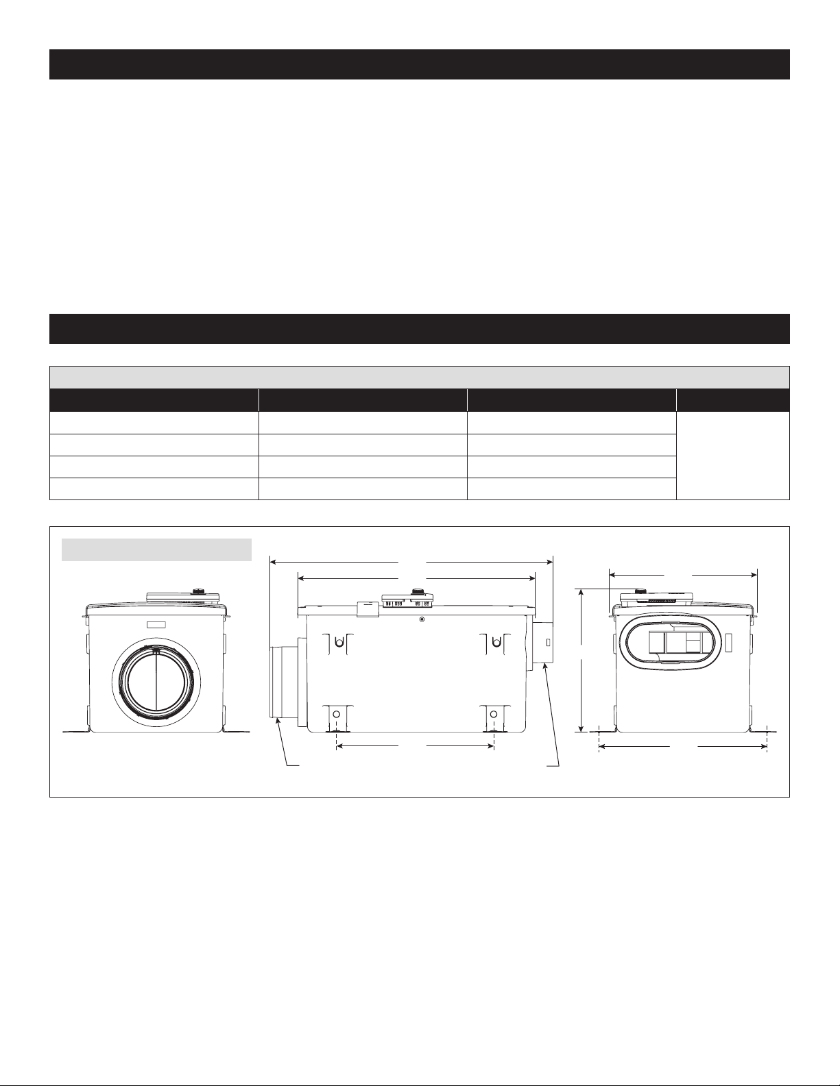
Specications � � � � � � � � � � � � � � � � � � � � � � � � � � � � � � � � � � � � � � � � � � � � � � � � � � � � � � 3
Install Electrical Outlet � � � � � � � � � � � � � � � � � � � � � � � � � � � � � � � � � � � � � � � � � � � � � 4
Ventilator Location and Orientation� � � � � � � � � � � � � � � � � � � � � � � � � � � � � � � 4
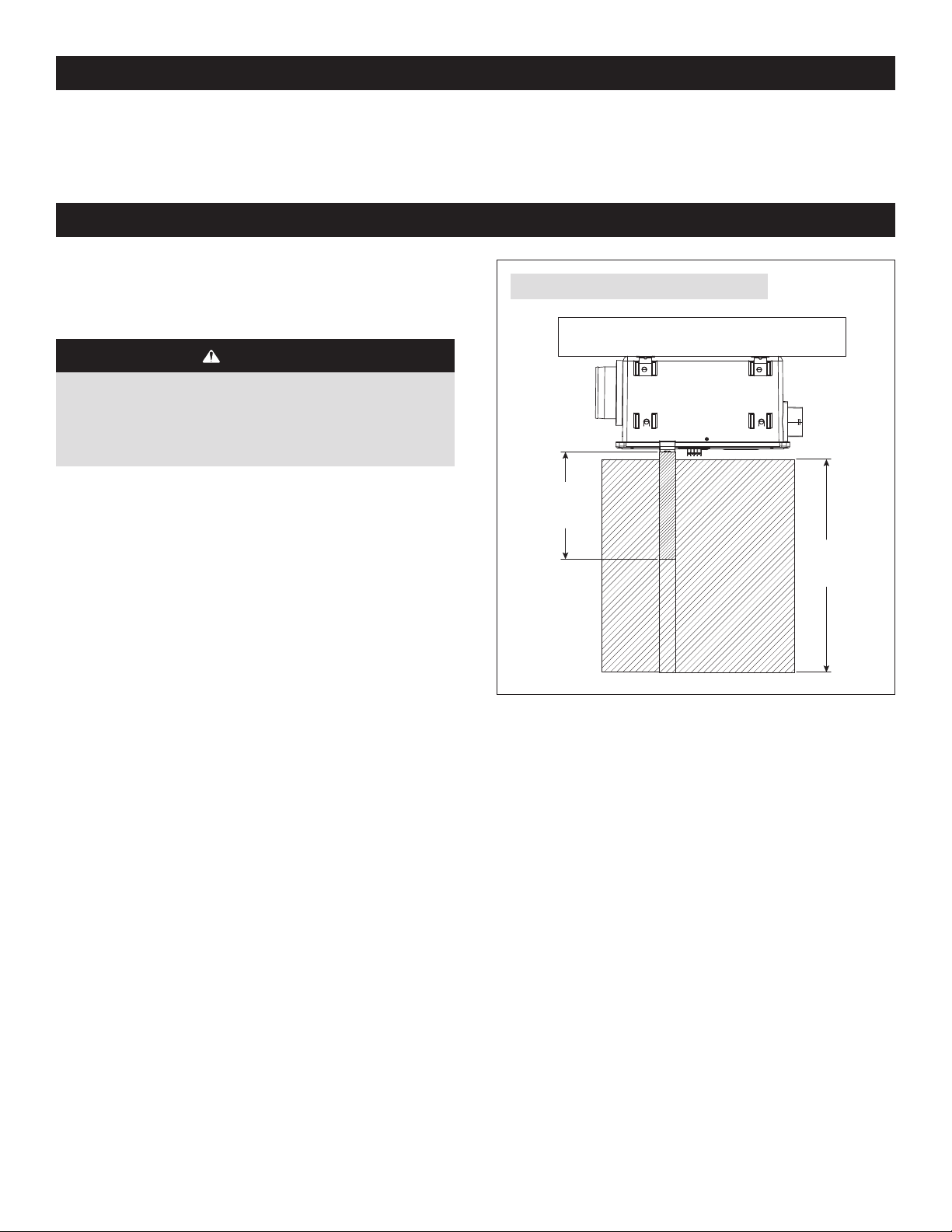
Mount the Ventilator � � � � � � � � � � � � � � � � � � � � � � � � � � � � � � � � � � � � � � � � � � � � � � � 5
Mount Intake Hood � � � � � � � � � � � � � � � � � � � � � � � � � � � � � � � � � � � � � � � � � � � � � � � � � 6
Install Ductwork � � � � � � � � � � � � � � � � � � � � � � � � � � � � � � � � � � � � � � � � � � � � � � � � � � � � 6
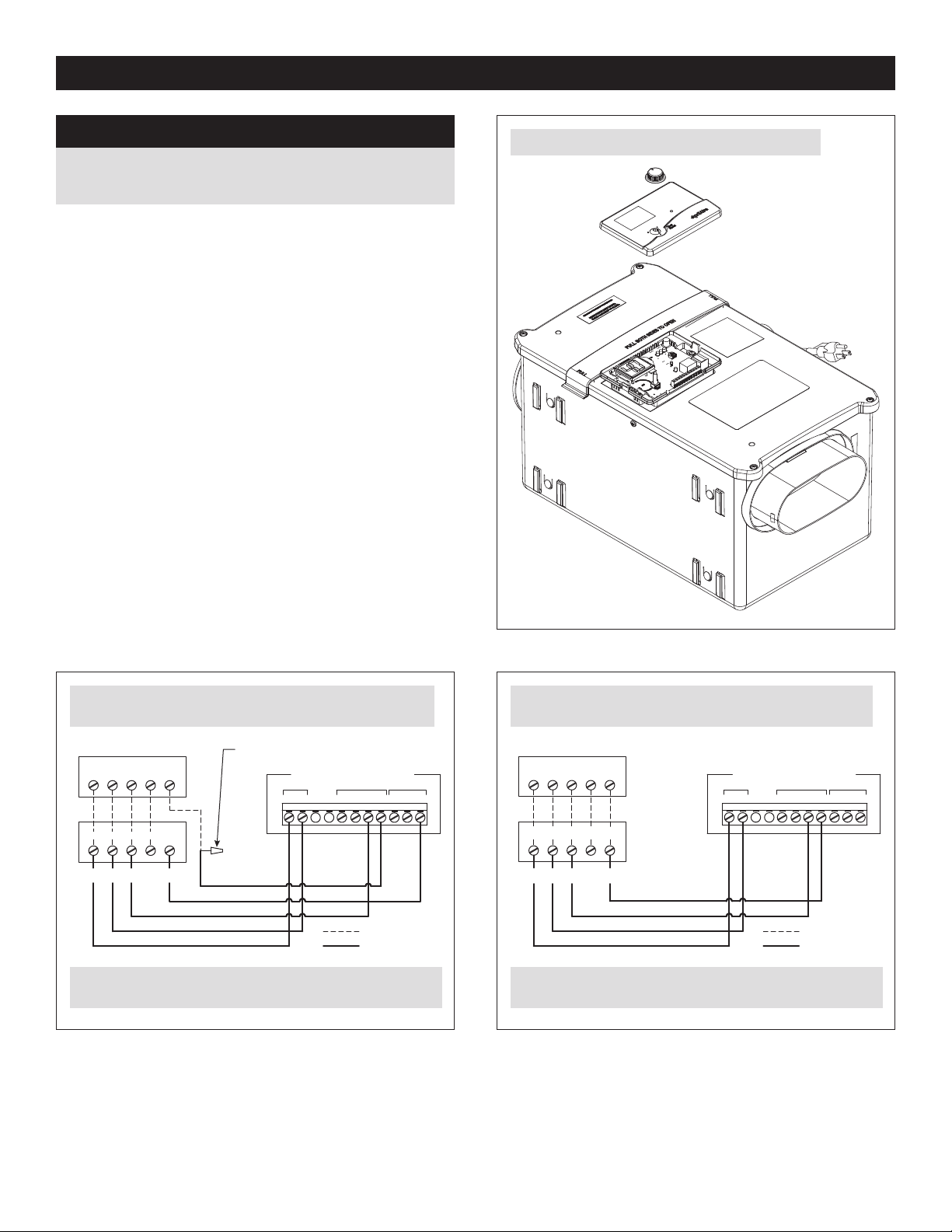
Wiring the Control to the HVAC System � � � � � � � � � � � � � � � � � � � � � � � � � � � 7
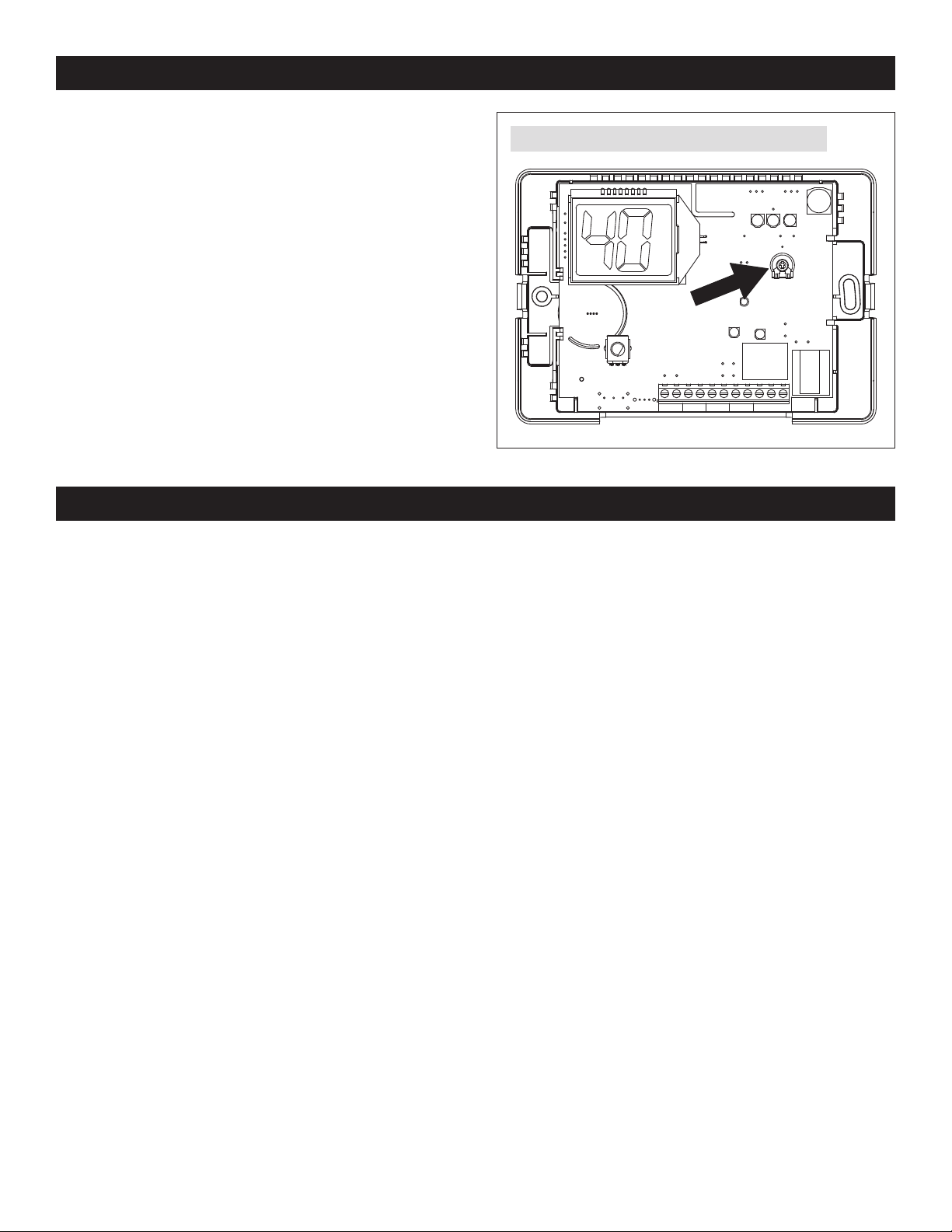
Set Up � � � � � � � � � � � � � � � � � � � � � � � � � � � � � � � � � � � � � � � � � � � � � � � � � � � � � � � � � � � � � � � 8
Test� � � � � � � � � � � � � � � � � � � � � � � � � � � � � � � � � � � � � � � � � � � � � � � � � � � � � � � � � � � � � � � � � � 8
Measure Delivered Airow � � � � � � � � � � � � � � � � � � � � � � � � � � � � � � � � � � � � � � � � � 9
Determine Ventilation Time Setting � � � � � � � � � � � � � � � � � � � � � � � � � � � � � � 10
Start Up and Sequence of Operation � � � � � � � � � � � � � � � � � � � � � � � � � � � � � 11
Filter Cleaning � � � � � � � � � � � � � � � � � � � � � � � � � � � � � � � � � � � � � � � � � � � � � � � � � � � � � � 11
Internal Schematics� � � � � � � � � � � � � � � � � � � � � � � � � � � � � � � � � � � � � � � � � � � � � � � 12
Limited Warranty � � � � � � � � � � � � � � � � � � � � � � � � � � � � � � � � � � � � � � � � � � � � � � � � � � 12

3
INTRODUCTION AND COMPLIANCE STATEMENT
The Model 8145A Fresh Air Ventilator is designed to bring in precisely the right amount of outdoor air into today’s efciently designed
homes� Duct the inlet of the ventilator to an outdoor air intake and duct the discharge to the HVAC system, then simply plug the unit in,
set the amount of needed ventilation and select the desired temperature limits�
When properly installed and set, the Model 8145A Fresh Air Ventilator will meet the mechanical ventilation requirements of:
Energy Star Certied Homes
EPA Indoor airPLUS
2012-2018 International Residential Code (IRC)
2012-2018 International Energy Conservation Code (IECC)
California Energy Commission Title 24
ASHRAE Standard 62�2-2010
ASHRAE Standard 62�2-2013 & 2016
SPECIFICATIONS
TABLE 1 – SPECIFICATIONS
External Static Pressure (“w.c.) Airow (CFM) Efcacy (CFM/watt) Voltage
0�0 210 5�2
120 VAC
1 phase
60 Hz
0�2 180 4�4
0�4 150 3�5
0�6 120 2�8
23.41
19.66
13.00
INLET: ROUND COLLAR
FOR 6” DIAMETER DUCT
OUTLET: OVAL COLLAR
FOR 6” DIAMETER DUCT
12.25
13.90
11.85
90-2713
FIGURE 1 – DIMENSIONS (INCHES)

4
VENTILATOR LOCATION AND ORIENTATION
If the outlet of the ventilator is not ducted, or if small sections of
collapsible duct (i.e. ex duct) are attached to the outlet, then
the ventilator must be mounted in a location which minimizes
interference with moving parts (see CAUTIONS below)�
CAUTION
1. Mount the blower with the lowest, exposed moving parts
at least 8 feet (2.4 m) above oor or grade level.
2. Mount the blower at least 3.3 feet (1.0 m) from any
accessible opening of the duct.
Choose a location for the ventilator that is within 6 feet of the
outlet into which the ventilator will be plugged� Allow space for
lter removal and service as shown in FIGURE 2�
The ventilator can be mounted in any orientation�
12”
FILTER
ACCESS
24”
FAN
ACCESS
90-2514
FIGURE 2 – CLEARANCES FOR SERVICING
INSTALL ELECTRICAL OUTLET
Install a standard NEMA 5-15 receptacle suitable for the location, near where the ventilator will be installed� The ventilator comes
equipped with a 6-foot power cord with a standard 3-prong plug�

5
MOUNT THE VENTILATOR
1. Select the appropriate brackets, large or small, for mounting the ventilator (see
FIGURE 3)� If mounting to the wall or hanging from joists, use the four small mounting
brackets� If mounting on or in between the oor joists, install all four smaller brackets
for 13” on center joists, or two small and two longer brackets for 16” on center joists�
2. Snap the brackets into the proper locations as shown in FIGURE 4� Use the mounting
locations nearest the cover for mounting between oor joists or hanging from rafters.
Use the mounting locations near the bottom of the unit for surface mounting (i�e� to a
at wall, ceiling surface or bottom of joists).
3. Screw the ventilator brackets into joists or a strong platform using the #10 x 3/4”
screws provided. The ventilator weighs approximately 15 pounds, so do not secure
into drywall alone�
BETWEEN JOISTS
HANGING
INSTALLATION SURFACE MOUNT
90-2514
FIGURE 4 – MOUNTING BRACKET POSITIONING
90-2514
FIGURE 3 – BRACKETS

6
MOUNT INTAKE HOOD
Install a weather tight hood with a bird screen�
Cut a hole in the exterior wall that is large enough to t 6” insulated exible duct through with minimal compression of the insulation.
Pull the duct through the hole and attach the ex duct to the collar of the hood. Use metal foil tape or a plastic zip-tie to secure the
duct to the collar� Pull the insulation and vapor barrier over the duct and tape it to the collar�
IMPORTANT: The end of the insulation must be sealed to prevent condensation from forming inside the insulation. If a plastic zip-
tie is used to secure the insulation to the hood collar, also tape the end to seal it against condensation problems.
Press the hood against the outside wall and secure in place with screws; seal around the perimeter of the hood with caulk�
INSTALL DUCTWORK
Install 6” diameter exible, insulated
duct from the round inlet collar of the
unit to the intake hood and from the
oval outlet collar of the unit to the HVAC
system� Duct the outlet of the ventilator
to the return side of the HVAC system
(refer to FIGURE 5)�
IMPORTANT: The end of the
insulation must be sealed to prevent
condensation from forming inside
the insulation. If a plastic zip-tie
is used to secure the insulation to
the hood collar, also tape the end
to seal it against condensation
problems.
FILTER
FURNACE/AIR HANDLER
AIR FLOW
FRESH AIR
VENTILATOR
FRESH AIR INTAKE DUCT
FRESH AIR
OUTSIDE
WALL
FRESH AIR
INTAKE HOOD
WITH
SCREEN
FRESH AIR
INTAKE HOOD
WITH
SCREEN
TYPICAL BASEMENT INSTALLATION
FRESH AIR
VENTILATOR
GABLE END WALL, BAND JOIST, OR PORCH SOFFIT
FRESH AIR
FRESH AIR INTAKE DUCT
RETURN MIXING BOX FURNACE/AIR
HANDLER
FILTER
AIR FLOW
TYPICAL ATTIC INSTALLATION
90-2514
FIGURE 5 – DUCTING IN UPFLOW AND HORIZONTAL HVAC SYSTEMS

7
WIRING THE CONTROL TO THE HVAC SYSTEM
NOTICE
Disconnect power to HVAC system during wiring to avoid
electrical shorts.
1. Remove the control knob and cover as shown in FIGURE 6.
Set aside in a safe place until all wiring has been completed�
2. Run a 4 or 5 conductor cable between the control and the
HVAC system�
3. Wire to the HVAC system in accordance with FIGURE 7 or
FIGURE 8�
VENTILATION CONTROL
R C USED
NOT ODT W G VENT GF
R C W Y G
R C W Y G
THERMOSTAT
HVAC SYSTEM CONTROL
WIRE NUT – FIELD SUPPLIED
EXISTING WIRE
NEW WIRING
GFVENTGWODT
NOT
USEDCR
VENTILATION CONTROL
R C W Y G
GYWCR
THERMOSTAT
HVAC SYSTEM CONTROL
EXISTING WIRE
NEW WIRING
90-2714
FIGURE 6 – REMOVE CONTROL KNOB AND COVER
FIGURE 7 – PREFERRED – VENTILATOR TURNS ON THE HVAC
SYSTEM BLOWER AS NEEDED
DO NOT REMOVE THE PRE-INSTALLED YELLOW OR BLACK
WIRES WHEN WIRING TO THE HVAC SYSTEM.
DO NOT REMOVE THE PRE-INSTALLED YELLOW OR BLACK
WIRES WHEN WIRING TO THE HVAC SYSTEM.
FIGURE 8 – ALTERNATE – VENTILATOR DOES NOT TURN ON
THE HVAC SYSTEM BLOWER
90-2001 90-2001

8
TEST
After all ducting and wiring is complete, plug in the ventilator, restore power to the HVAC system and make sure the switch controlling
the outlet into which the ventilator is plugged is turned on� Turn the thermostat to the OFF mode to ensure that wiring the HVAC system
has been done correctly� Rotate the Vent Time setting knob to Test/Reset:
1. The display will show “- -“, the green “Active Ventilation” led will blink�
2. The ventilator blower will start�
3. If the ventilator was properly wired to turn on the HVAC unit blower with ventilation, the HVAC blower will turn on�
4. After one minute the test will end and the display will blink and show the rmware revision level. Return the knob to the OFF position
until the desired Time Setting is determined�
RCODT WGVENT Gf
90-2005
FIGURE 9 – ADJUST HIGH/LOW TEMPERATURE LIMIT
SET UP
The control can be set up to prevent ventilation during the
hottest or coldest periods of the day� When the outdoor
temperature exceeds the high value or falls below the low
value, ventilation will stop and additional ventilation will be
brought in at a later time – See START UP AND SEQUENCE OF
OPERATION for details�
1. Turn the vent time setting knob to “OFF”�
2. Remove the knob then remove the cover to adjust the high/
low temperature limit�
3. Use a small at head screwdriver to turn the potentiometer
to select:
A – No limit, time only
B – 105°F high limit, 20°F low limit
C – 100°F high limit, 30°F low limit
D – 95°F high limit, 40°F low limit

9
MEASURE DELIVERED AIRFLOW
1. Make sure the ventilator is plugged in and the integral control is wired to the HVAC system�
2. Use 1/4” exible tubing to attach a pressure gauge set to “w.c. (sometimes shown as “in. w.g.” or “in. H2O”) to the inlet and outlet
pressure ports on the ventilator� The pressure gauge should have as small a range as possible to get a meaningful measurement
– a range of 1.0” w.c. should be sufcient. Connect the high or “+” port of the gauge to the outlet pressure port on the ventilator, and
the low or “-” port of the gauge to the inlet pressure port on the ventilator� See FIGURE 10�
3. Turn on the ventilator by turning the control knob to 60�
4. Use the label on the cover of the ventilator, or TABLE 2, to convert the pressure reading to delivered airow. If the pressure reading
falls between listed values, either use the lower value or interpolate between values: CFM = Lower Value + [(Higher Value – Lower
Value) * 10 * (Pressure Reading – Lower Value Pressure)]. The following is an example:
a. Measured Pressure Reading is 0�34” w�c�
b. TABLE 2 lists 200 CFM @ 0�3” w�c� and 170 @ 0�4” w�c�
c. Either use 170 CFM or interpolate:
CFM = 200 - [(200-170) *10 * (0.34-0.3)] = 200 - [(30) *10 *(0�04)] = 200 - 12 = 188 CFM
Interpolating will demonstrate higher delivered airow, but requires a calculation to be done.
TABLE 2 – DELIVERED AIRFLOW CORRESPONDING TO MEASURED
PRESSURE AT VENTILATOR PRESSURE PORTS
Measured Pressure (“w.c.) Delivered Airow (CFM)
0�1 255
0�2 225
0�3 200
0�4 170
0�5 145
0�6 115
0�7 90
INLET
OUTLET
Hi
-+
Lo
90-2719
FIGURE 10 – MEASURE PRESSURE AT INLET AND OUTLET
PRESSURE PORTS

10
DETERMINE VENTILATION TIME SETTING
CALCULATING AIRFLOW REQUIREMENT
1. The MINIMUM ventilation requirement is calculated using
ASHRAE 62�2-2010�
ASHRAE Airow in CFM = [House Area in Sq. Ft. x 0.01] +
[(Number of Bedrooms +1) x 7.5]
NOTE: Use ‘Number of Bedrooms + 1’ or ‘Number of
Occupants’, whichever is larger�
2. TABLE 3 shows the calculated airow values to the nearest
5 CFM�
3. Record the required CFM�
TABLE 3 – CFM REQUIRED
House
Sq. Ft.
Number of Bedrooms
2 3 4 5 6 7
1000 35 40 50 55 65 70
1500 40 45 55 60 70 75
2000 45 50 60 65 75 80
2500 50 55 65 70 80 85
3000 55 60 70 75 85 90
3500 60 65 75 80 90 95
4000 65 70 80 85 95 100
4500 70 75 85 90 100 105
5000 75 80 90 95 105 110
MEASURE VENTILATION AIR (CFM) DELIVERY RATE AND SELECT VENT TIME
1. Measure the outdoor air ow (CFM) through the duct that is bringing in only outdoor air.
2. Use the CFM Delivered along with the CFM required to nd the Cycle Time per hour setting from TABLE 4. For example if the
ventilator is providing 120 CFM, and the requirement is 70 CFM, set the time to 35 minutes�
3. Use the control knob to set the vent time to the determined minutes per hour� NOTE: knob can be set halfway between printed
numbers to achieve 5 minute increments�
TABLE 4 – CYCLE TIME SETTING (MINUTES) FOR AIRFLOW DELIVERED VS� AIRFLOW REQUIRED FOR 1 HOUR CYCLE
CFM Delivered
CFM Required
20 30 40 50 60 70 80 90 100 110
60 20 30 40 50 60
80 15 25 30 40 45 55 60
100 15 20 25 30 35 40 50 55 60
120 15 15 20 25 30 35 40 45 50 55
140 15 15 15 20 25 30 35 40 45 50
160 15 15 15 20 25 25 30 35 40 45
180 15 15 15 20 20 25 30 30 35 40
200 15 15 15 15 20 25 25 30 30 35
220 15 15 15 15 20 20 20 25 30 30

11
FILTER CLEANING
Normally, the fresh air lter will need to be removed and cleaned every six months, but check it after the rst three months following
installation to determine if more or less frequent cleaning will be necessary. After cleaning the lter inside the ventilator, clean off
the screen at the fresh air intake hood on the outside of the house� The most common cause of reduced ventilation is a clogged air
intake hood�
START UP AND SEQUENCE OF OPERATION
Set the Ventilation Time knob to the setting that was determined in the previous section� The ventilator will turn on with the HVAC
equipment for the set number of minutes during the one-hour cycle period� If the HVAC equipment does not turn on enough, the
ventilator will turn on, and will turn on the HVAC system blower if wired to do so, at the end of the one-hour cycle period to ensure
the desired ventilation time is met. The rst time it turns on, it will stay on for ve minutes to get an accurate air temperature
measurement� If the air temperature is within the range that is set (see SET UP), the ventilator will turn on for the amount of time
selected within the one-hour cycle period�
If the air temperature is outside of the set range, then no additional ventilation will occur for another hour, and the cycle period will
automatically adjust to four hours� When the ventilator starts again, it will sample the air temperature and if in range, will meet the set
amount of ventilation during the four-hour cycle period. For example, if the Vent Time was set to 25 minutes per hour and the rst time
the ventilator came on it measured an air temperature above the high limit setting, it would turn off after ve minutes. The control will
automatically change the cycle period to four hours and work to provide the additional 95 total minutes of ventilation (25 min/hr *
4 hours = 100 minutes, minus the ve minutes of the rst air sampling) during the four-hour cycle period.
If the air temperature is still out of range, the control will automatically switch to an 8-hour cycle period, then a 12-hour cycle period
and nally a 24-hour cycle period. During 8, 12 and 24 hour cycle periods, the total ventilation time increases to compensate for
ventilation effectiveness as dened in ASHRAE Standard 62.2-2010. When the cycle period automatically adjusts to 24-hours, the
control will turn on ventilation to meet the requirements even if the temperature is outside of the set limits�
To clean the ventilator lter
(see FIGURE 11):
1. Flex the outside edges of
the lter door to disengage
it from the housing�
2. Lift the lter door to remove
the lter from the ventilator.
3. Use water to rinse the
lter and shake the excess
moisture off the lter.
4. Replace the lter in the
ventilator and press the
outside edges of the lter
door to snap it in place�
FILTER DOOR
FIGURE 11
90-2715

12
LIMITED WARRANTY
Your AprilAire® Fresh Air Ventilator is expressly warranted for ve (5) years from date of installation to be free from defects in materials or workmanship.
AprilAire’s exclusive obligation under this warranty shall be to supply, without charge, a replacement for any component which is found to be defective within such
ve (5) year period and which is returned not later than thirty (30) days after said ve (5) year period by you to either your original supplier or to AprilAire, Madison,
Wisconsin 53701, together with the model number and installation date of the ventilator�
THIS WARRANTY SHALL NOT OBLIGATE APRILAIRE FOR ANY LABOR COSTS AND SHALL NOT APPLY TO DEFECTS IN WORKMANSHIP OR MATERIALS FURNISHED BY YOUR INSTALLER AS
CONTRASTED TO DEFECTS IN THE VENTILATOR ITSELF�
IMPLIED WARRANTIES OF MERCHANTABILITY OR FITNESS FOR A PARTICULAR PURPOSE SHALL BE LIMITED IN DURATION TO THE AFORESAID FIVE YEAR PERIOD� APRILAIRE’S LIABILITY
FOR INCIDENTAL OR CONSEQUENTIAL DAMAGES, OTHER THAN DAMAGES FOR PERSONAL INJURIES, RESULTING FROM ANY BREACH OF THE AFORESAID IMPLIED WARRANTIES OR THE
ABOVE LIMITED WARRANTY IS EXPRESSLY EXCLUDED� THIS LIMITED WARRANTY IS VOID IF DEFECTS(S) RESULT FROM FAILURE TO HAVE THIS UNIT INSTALLED BY A QUALIFIED HEATING
AND AIR CONDITIONING CONTRACTOR� IF THE LIMITED WARRANTY IS VOID DUE TO FAILURE TO USE A QUALIFIED CONTRACTOR, ALL DISCLAIMERS OF IMPLIED WARRANTIES SHALL
BE EFFECTIVE UPON INSTALLATION�
Some states do not allow limitations on how long an implied warranty lasts or the exclusion or limitation of incidental or consequential damages so the above
exclusion or limitations may not apply to you.
This warranty gives you specic legal rights and you may also have other rights which vary from state to state.
WARRANTY REGISTRATION
Visit us online at aprilaire.com to register your AprilAire product� If you do not have online access, please mail a postcard with your name, address, phone number,
email address, product purchased, model number, date of purchase, and dealer name and address to: AprilAire, P.O. Box 1467, Madison, WI 53701.
Your warranty registration information will not be sold or shared outside of this company.
B2209888A • 10016215 • 4.22
© 2022 AprilAire | aprilairepartners.com | 800.334.6011
AprilAire reserves the right to change specications without notice.
INTERNAL SCHEMATICS
RED
GRN
BLU
BRN
GRN
L2-WHT
L1-BLK
BLK
WHT
YLW
YLW
ORG
N
L
120 VAC
CON3
CON2
CON3
ORG
WHT
RED
BLU
CAPPED RED & WHITE WIRES ARE LOCATED INSIDE THE FILTER DOOR TO POWER THE CONTROL (R & C TERMINALS) FROM
THE POWER PCB ASSEMBLY. USE ONLY IF THE VENTILATON CONTROLLER WILL NOT BE WIRED TO THE HVAC SYSTEM.
M
M
BLOWER
RUN CAPACITOR
CHASSIS GROUND
GND
CHASSIS
GROUND
DAMPER
MOTOR
POWER PCB ASSEMBLY
VENTILATION CONTROL
R C USED
NOT ODT W G VENT Gf
FIGURE 12 – MODEL 8145A INTERNAL SCHEMATIC
90-2716
MANUFACTURING
USE ONLY
Table of contents
Other Aprilaire Fan manuals

Aprilaire
Aprilaire 8145NC User manual

Aprilaire
Aprilaire 8100 User manual

Aprilaire
Aprilaire 8142A User manual

Aprilaire
Aprilaire ARNHPF Manual

Aprilaire
Aprilaire 8144NC User manual

Aprilaire
Aprilaire 8142 User manual

Aprilaire
Aprilaire 8192A User manual

Aprilaire
Aprilaire 8100 User manual

Aprilaire
Aprilaire 8100 User manual

Aprilaire
Aprilaire 8190FF User manual