nfortec DYS User manual

INSTRUCTIONS MANUAL
MANUAL DE INSTRUCCIONES
RGB GAMING TOWER
DYS

205mm 340mm
412mm
TECHNICAL SPECIFICATIONS
ESPECIFICACIONES TÉCNICAS
MODEL DYS
DIMENSIONS (L x W x H) 340mm x 205mm x 412mm
WEIGHT 4,9Kg
MATERIAL Steel 0,6mm SPCC, tempered glass
FANS LOCATION
Front: 3x 120mm (2x RGB included)
2x 140m
Rear: 1x 120mm (1x RGB included)
Top: 2x 120mm
2x 140mm
EXPANSION SLOTS x4
FRONT I/O
USB 3.0 x1
USB 2.0 x2
Headphone/Microfone x1
Power
LED RGB Control
DUST FILTER
1x Top (Magnetic)
1x Bottom
MOTHERBOARD TYPE MicroATX, ITX
POWER SUPPLY ATX up to 180mm (not included) bottom position
VGA (GPU) Up to 330mm (not included)
CPU COOLER Up to 160mm (not included)
MODELO DYS
DIMENSIONES (L x An x Al) 340mm x 205mm x 412mm
PESO 4,9Kg
MATERIAL Acero 0,6mm SPCC, cristal templado
UBICACIÓN DE
VENTILADORES
Parte delantera: 3x 120mm (2x RGB incluidos)
2x 140mm
Parte trasera: 1x 120mm (1x RGB incluido)
Top: 2x 120mm
2x 140mm
RANURAS DE EXPANSION x4
E/S FRONTAL
USB 3.0 x1
USB 2.0 x2
Auricular/Microfono x1
Encendido/Apagado
LED RGB Control
FILTROS ANTIPOLVO
1x Parte superior (Magnético)
1x Parte inferior
TIPO DE PLACA BASE MicroATX, ITX
FUENTE DE
ALIMENTACION
Formato ATX hasta 180mm (no incluida) colocada en la
parte inferior
TARJETA GRÁFICA (GPU) Hasta 330mm (no incluida)
DISIPADOR CPU Hasta 160mm (no incluido)

PC CASE GENERAL DIAGRAM
DIAGRAMA DE INFORMACIÓN GENERAL
Magnetic Dust filter Front mesh panel HDD/SSD enclosure bays
Filtro de polvo magnético Panel frontal mallado Bahías para discos duros HDD
y SSD
1 4 7
Side tempered glass 120mm RGB Fans Front panel I/O
Cristal templado lateral Ventiladores RGB 120mm Panel frontal de E/S
2 5 8
Back metal side PSU enclosure bay PCI expansion bays
Lateral trasero metálico Bahía independiente para fuente
de alimentación
Ranuras de expansión PCI
3 6 9
1
2
45
9
3
8
7
6
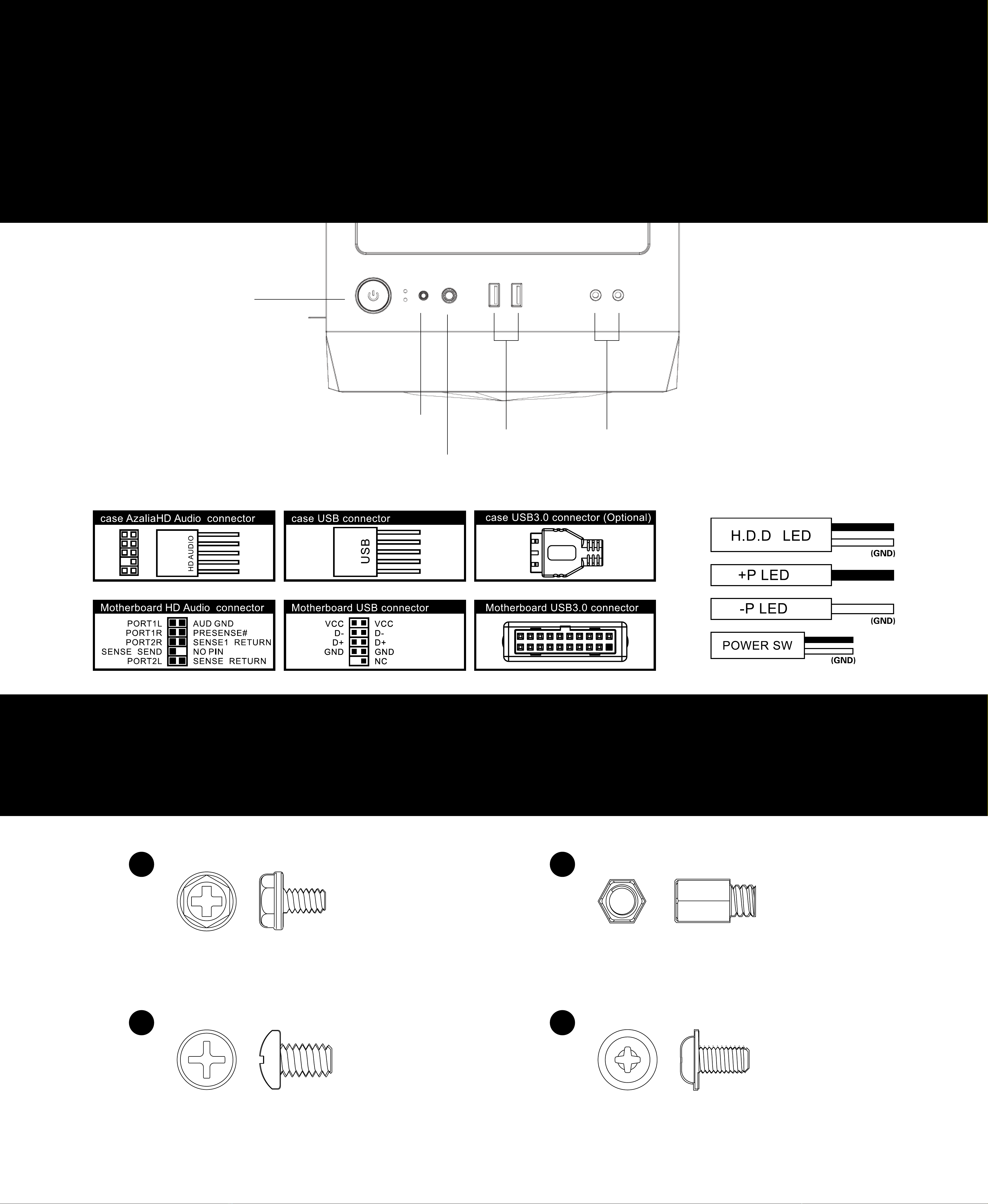
FRONT PANEL I/O AND
MOTHERBOARD CONNECTORS
PANEL FRONTAL DE E/S Y CONECTORES PARA PLACA BASE
ACCESORY BAG
ACCESORIOS PARA INSTALACION
Power
Reset
LED Button
USB3.0 HD AUDIO
PSU screws
HDD screws Motherboard Screws
Motherboard standos
x 7
x 6 x 12
x 6
Tornillos para Fuente de alimentación
Tornillos para disco duro Tornillos para placa base
Soportes para placa base
1
3 4
2
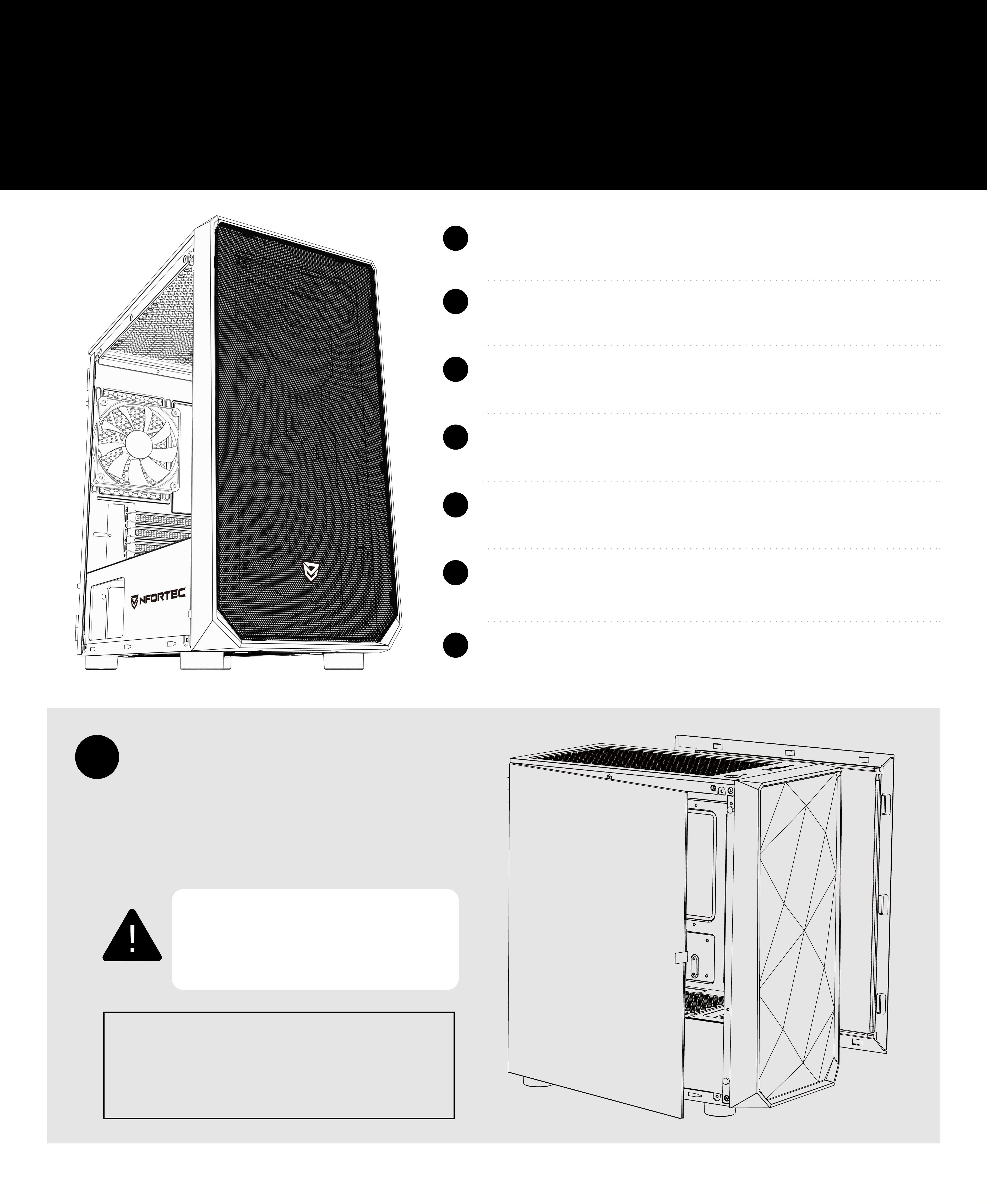
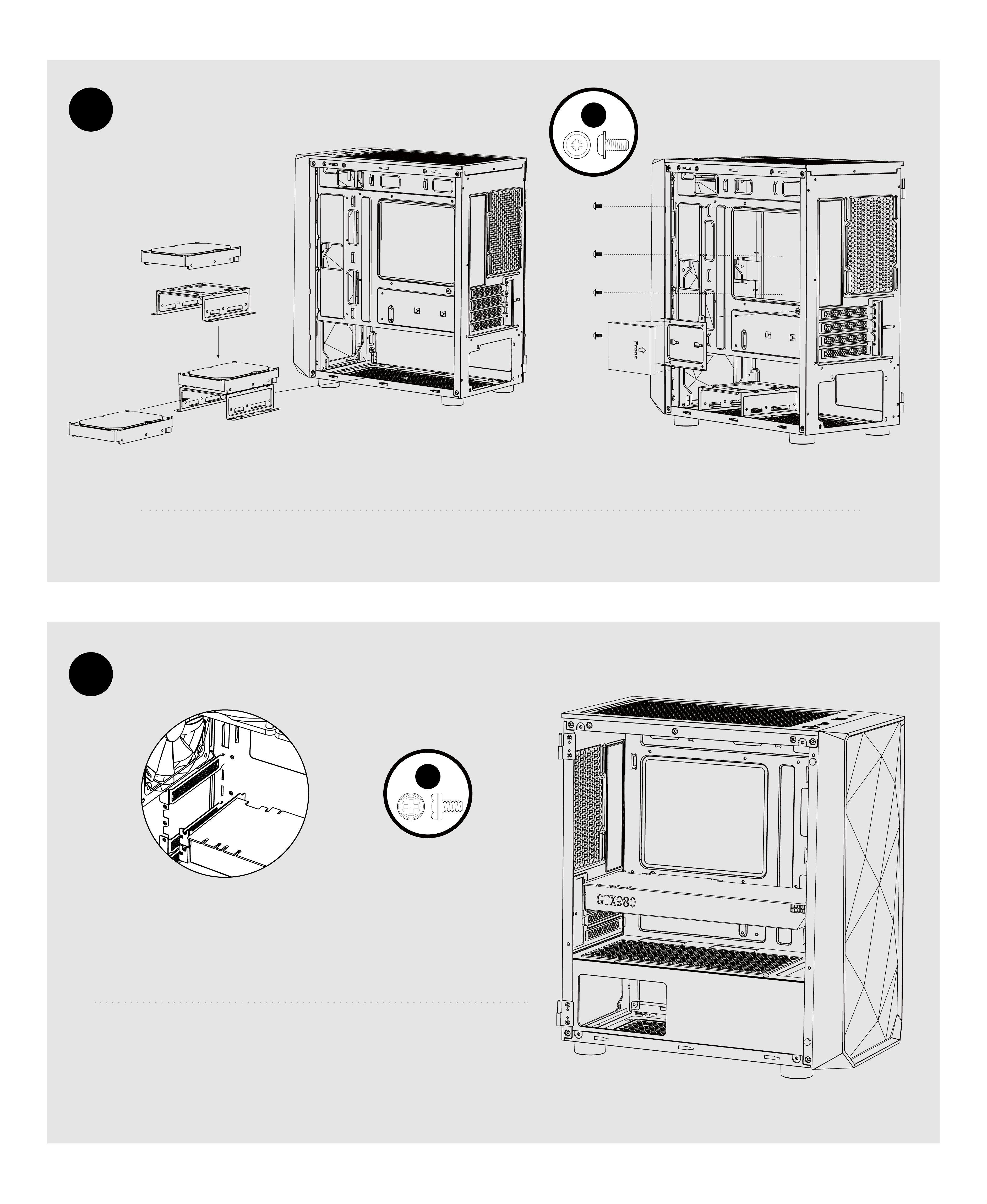
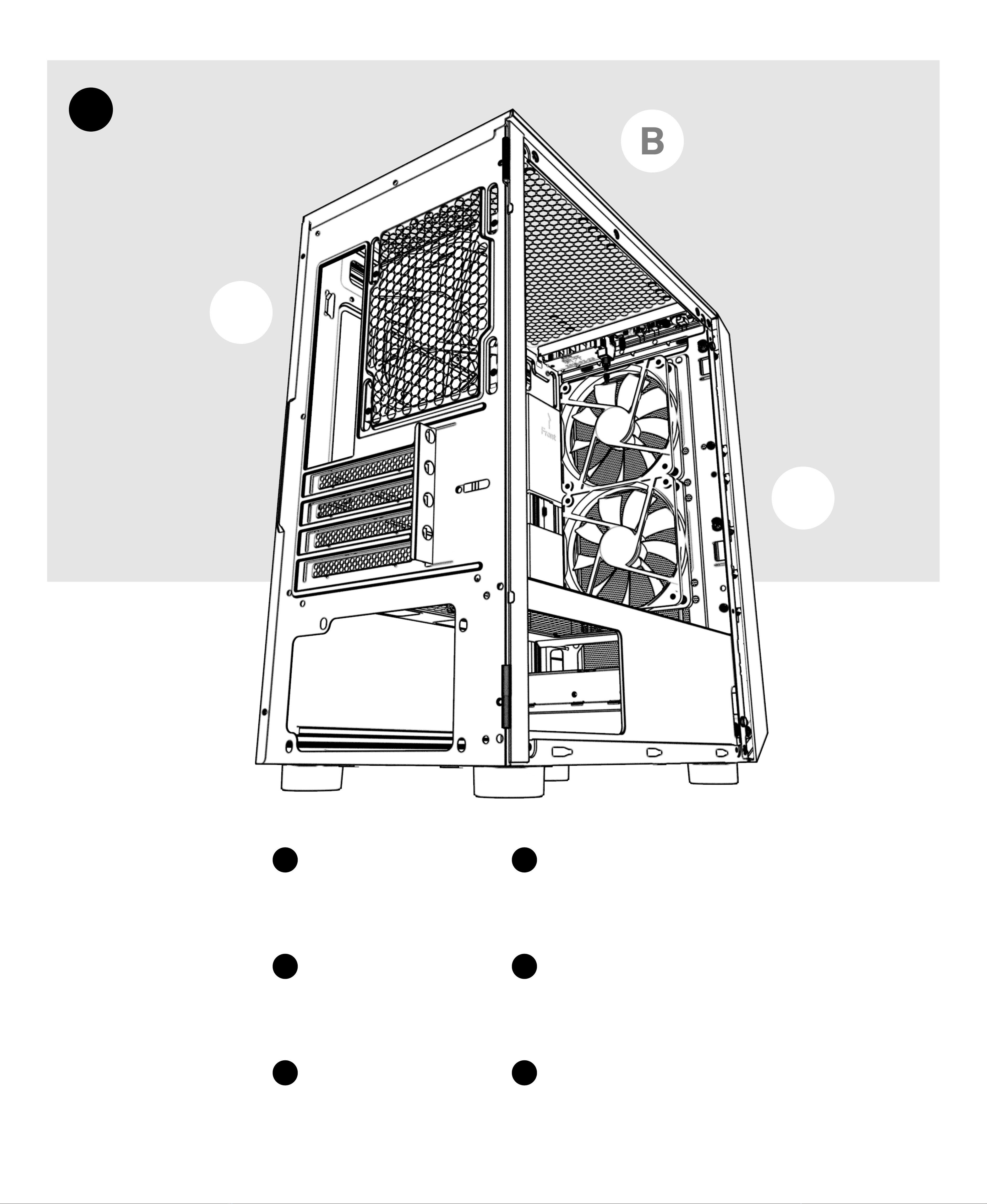
BASIC INSTALLATION
INSTALACIÓN BÁSICA
Disassemble the side panel and the front panel.
Install the power supply.
Install the motherboard.
Install HDD/SSD.
Install VGA card and disassemble the expansion slot.
Install fan and radiator (optional).
A-RGB Sync Installation.
Desmontar los paneles laterales y el panel frontal.
Instalación de la fuente de alimentación.
Instalación de la placa base.
Instalación de discos duros HDD/SSD.
Instalación de tarjeta gráfica y desmontar el slot de expansión PCI.
Instalación de ventiladores y/o radiadores (opcional).
Instalación cable para sincronización A-RGB.
Take out the screws before disassembling
side panel.
Quitar los tornillos de ambos paneles laterales antes de
desmontar el panel lateral.
Open the side panel glass to 90° and then lift
up to take out the hinges.
Abrir el panel lateral de cristal hasta los 90° mínimo y
luego levantar hacia arriba para sacarlo de las bisagras.
A
A
B
C
D
E
F
F
Special attention to the tempered
glass side panel. Handle with care.
Precaución al desmontar el panel de cristal
templado. Manejar con cuidado.

B
C
Make sure the screw holes for PSU and the PC case are aligned before screwing.
Make sure that the motherboard aims at the
copper cylinder and install the standoffs (No.2)
before screwing in with the No.4 screws.
Asegúrate que los huecos para los tornillos de la fuente de alimentación se alinean de manera correcta
con los de la torre antes de atornillar.
Asegúrate que la placa base se alinea con los huecos
marcados en la torre e instala los alzadores de cobre
(No.2) antes de atornillar la placa base a la torre con
los tornillos No.4
MiniITX
MicroATX
1
2
12
24
1
D
E
Take o the hard disk enclosure for both HDD and SSD and install it with No.4 screws
Remove the bale marked in the picture, make sure
the VGA card aims at the motherboard slot and
then fix VGA card and case with No.1 screw.
Desmonta el soporte para los discos HDD y SSD e instálalos con los tornillos No.4
Retira el embellecedor que necesites alineando con la
ranura PCI de la placa base, luego instala la tarjeta gráfica y
asegúrala a la torre con el tornillo No.1
4
1
F
B
A
C
FRONT FRONTAL
TOP SUPERIOR
REAR TRASERO
Fans → 3x 120mm
→ 2x 140mm
Radiator up to 240mm
Ventiladores → 3x 120mm
→ 2x 140mm
Radiador hasta 240mm
Fans → 2x 120mm
→ 2x 140mm
Radiator up to 240mm
Ventiladores → 2x 120mm
→ 2x 140mm
Radiador hasta 240mm
Fans → 1x 120mm
Radiator up to 120mm
Ventiladores → 1x 120mm
Radiador hasta 120mm
A A
B B
C C
G
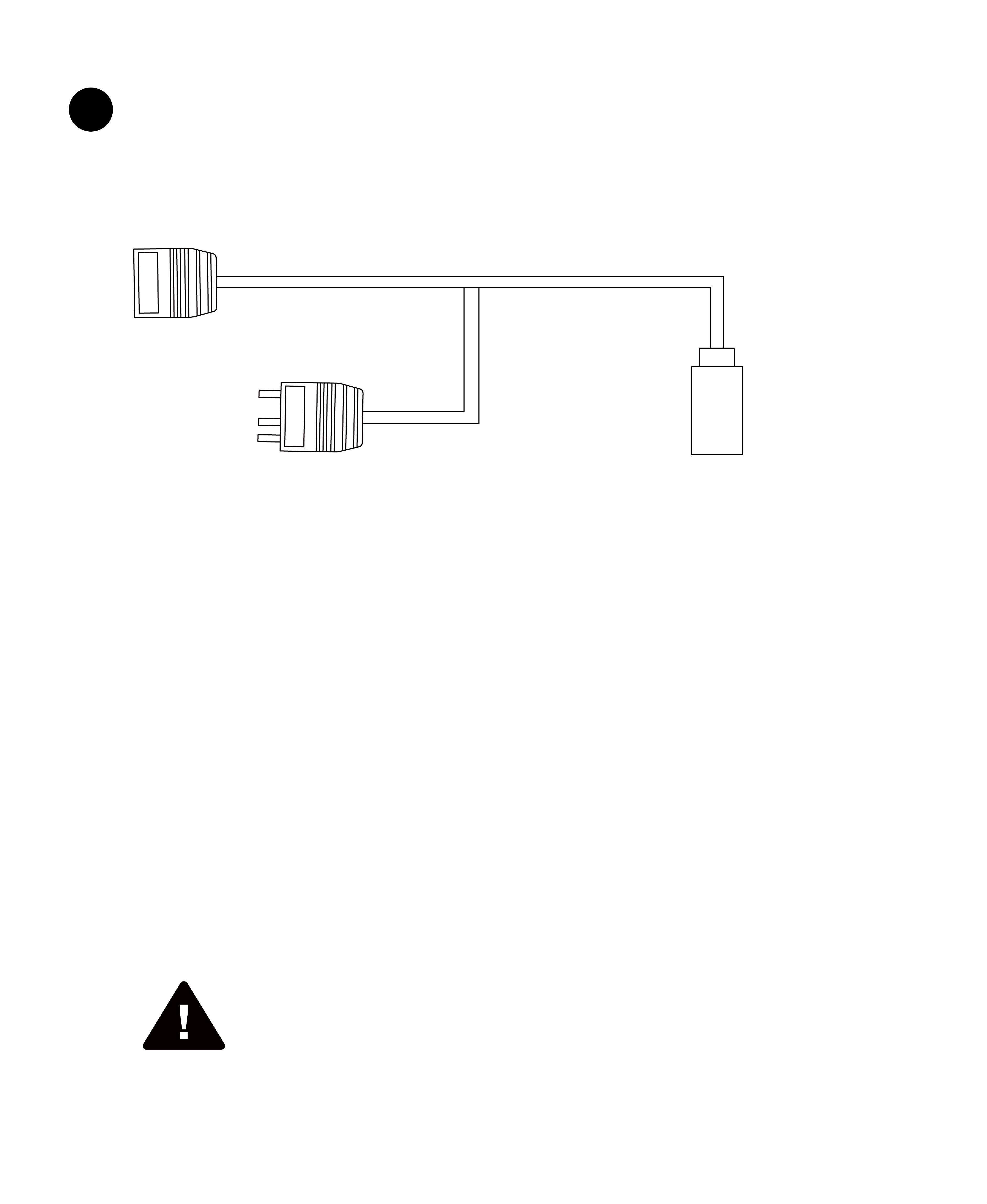
5V 3PIN A-RGB TO MOTHERBOARD
5V 3PIN A-RGB BRIDGE RESET SW TO CONTROL COLOUR MODES
BY CASE LED/RESET BUTTON
IF NOT SYNC WITH CONTROLLER HUB OR
MOTHERBOARD
CONECTOR A PLACA BASE DE 5V 3PIN A-RGB
CONECTOR PUENTE PARA OTROS
DISPOSITIVOS A-RGB
CONECTOR A RESET SW DE LA CAJA/TORRE
PARA CONTROLAR LOS MODOS DE COLOR EN
CASO DE NO CONECTAR LA SINCRONIZACION A
PLACA BASE O A UNA CONTROLADORA EXTERNA
To synchronize the lighting with the motherboard, connect the 3pin 5v A-RGB female
cable to the motherboard (check manufacturer's manual). There is a male connector in
case you want to synchronize additional devices.
In case of not having synchronization on the motherboard, connect the
SW cable to the front RESET/LED connector to be able to change the
dierent lighting modes.
Para sincronizar la iluminación con la placa base, conectar el cable hembra de 3pin 5v A-RGB a la placa
base (revisar manual del fabricante). Dispone de un conector macho en caso de querer sincronizar
dispositivos adicionales.
En caso de no disponer de sincronización en la placa base, conectar el cable SW al
conector del frontal RESET/LED para poder cambiar los distintos modos de iluminación.

RGB GAMING TOWER
DYS
Table of contents


