Niagara ECO-IQ N9195 Manual

®
ECO•IQ™#N9195
5-2 Programmable Electronic Thermostat Heat/Cool
Termostato electrónico programable de calefacción/enfriamiento 5-2
INSTALLATION & OPERATING
INSTRUCTIONS (PAGES 1-24)
INSTALACIÓN E INSTRUCCIONES
DE OPERACIÓN (PAGES 25-48)

2
Compatible with low voltage single stage gas, oil or electric heating or cooling systems and single stage heat
pumps. For use on 24VAC systems (not to exceed 30VAC) and 250mv to 750mv millivolt heating only systems.
WARNING!
• To prevent electrical shock and/or equipment damage, disconnect electric power to system at main fuse or circuit
breaker box until installation is complete.
• Do not use this thermostat on applications with voltages above 30VAC. Wiring must conform to all local and
national building/electrical codes and ordinances.
• Do not short (jumper) across terminals on the gas valve or at the system control to test the installation. This will
damage the thermostat and void the warranty.
• This thermostat is equipped with automatic compressor protection to prevent damage due to short cycling. The
short cycle protection provides a 5-minute delay between heating (heat pump models) or cooling cycles to prevent
the compressor from being damaged.
• Do not switch the system to cool if the outdoor temperature is below 50°F (10°C). This may damage the cooling
system and may cause personal injury. This thermostat should be used only as described in this manual.

3
SPECIFICATIONS
Electrical Rating 24 Volt AC (18-30 VAC)
1 Amp Maximum per Terminal
2 Amps Total Load
Control 1 Heat / 1Cool Single Stage Heat Pump
Set Point Range 45°F – 90°F (7.0°C – 32.0°C)
Program 5 - 2 (Mon-Tue-Wed-Thur-Fri) & (Sat-Sun)
Set Points Morn, Day, Eve, Night
Advanced Recovery Yes
Accuracy +/- 1°F (.5°C)
Terminations RC, RH, C, G, Y, W, B, O
Power 24VAC

4
INSTALLATION
REMOVING THE EXISTING THERMOSTAT
1. CAUTION: Make certain the power to the system has been disconnected.
2. Remove the cover of the old thermostat and locate the wires that are connected to the terminal board.
IMPORTANT: Before removing these wires, NOTE (ON A PIECE OF PAPER) THE COLOR OF EACH WIRE AND THE
CORRESPONDING TERMINAL MARKING ON THE OLD THERMOSTAT.
3. Remove the wires from the terminals. Remove the old thermostat and mounting base from the wall.
INSTALLING THE NEW THERMOSTAT
1. CAUTION: Make certain the power to the system has been disconnected.
2. If this is a new installation, locate the thermostat 4 to 5 feet above the oor in accordance with applicable codes.
Select a location that provides good airow. Avoid locations in direct sunlight, near sources of heat, or near air vents.
NOTE: The display is designed to be best viewed from a front downward angle.
3. Remove the back plate of the thermostat by gently depressing the bottom locking tab and swinging the back plate
up and away.
4. Place the back plate against the wall in the desired mounting location with the thermostat wires protruding from the
wall through the large rectangular hole in the back plate.
5. Mark placement of the (2) mounting holes (oval shaped holes in back plate) on the wall, remove the back plate, and
drill (2) 3/16” holes.
6. Tap supplied plastic anchors into the holes.

5
INSTALLATION
7. Secure the back plate to the wall with the supplied screws making certain the thermostat wires have been inserted
through the large rectangular hole in the back plate.
8. Carefully attach the thermostat wires to the appropriate connections on the terminal board on the back plate. Use the
notes taken from step 2 of “Removing The Existing Thermostat” to determine their location on the new thermostat.
Reference wiring diagrams are available in the back of this manual.
9. Carefully place the thermostat body face down on a soft surface to expose the main circuit board. Reference circuit
diagram in the back of this manual. Gently set the following switches in the correct position for the application:
• GAS / ELECTRIC (SW2): Congures the thermostat to either gas/oil or electric heating systems. For electric, set the
switch to HE. For gas, set the switch to HG.
• C / F (SW1): Sets the display in either Celsius or Fahrenheit.
• NORM / HP (SW5): Congures the thermostat for normal heating/cooling systems or heat pump systems
(single stage).
• ON/OFF (ARM): Switch should always be set to ON to avoid any system problems.
10. Attach the thermostat body to the back plate by resting the top of the thermostat body on the two clips on the upper
portion of the back plate. Then gently press the front body into place until the bottom locking tab snaps into place.
NOTE: The terminal board pins must be properly aligned with the sockets on the terminal board (on the back plate) in
order for the front body to properly snap into place.
11. Set the SYSTEM switch, located on the front face, to the OFF position.
12. Set the FAN switch, located on the front face, to the AUTO position.

6

7
SWITCH FUNCTION DEFAULT SETTING
System (COOL – OFF – HEAT) Select system mode from Cool, Off or Heat. OFF
Fan (AUTO – ON) Select fan operation from Auto or On. Auto
KEY FUNCTION
Increase temperature Press and hold both keys to access
Key Lock Setting mode.
Decrease temperature
TIME/DAY 1. Enter Time setting mode and select hour, minute and day setting.
2. Select program time in Program setting mode.
3. Set Day in Vacation hold.
PROGRAM 1. Enter Program setting mode and select program.
2. Hold 3 seconds to reset all programs to Energy Star default.
VACATION 1. Enable Vacation hold.
2. Review Vacation hold if it is set beforehand.
RUN 1. Return to Normal mode.
2. In Normal mode, press RUN for 1 second to cancel Vacation or Temporary hold.
3. In Normal mode, press RUN and PROGRAM to enter the conguration menu.
RESET Resets the thermostat to factory default settings.
CONTROLS
8
9
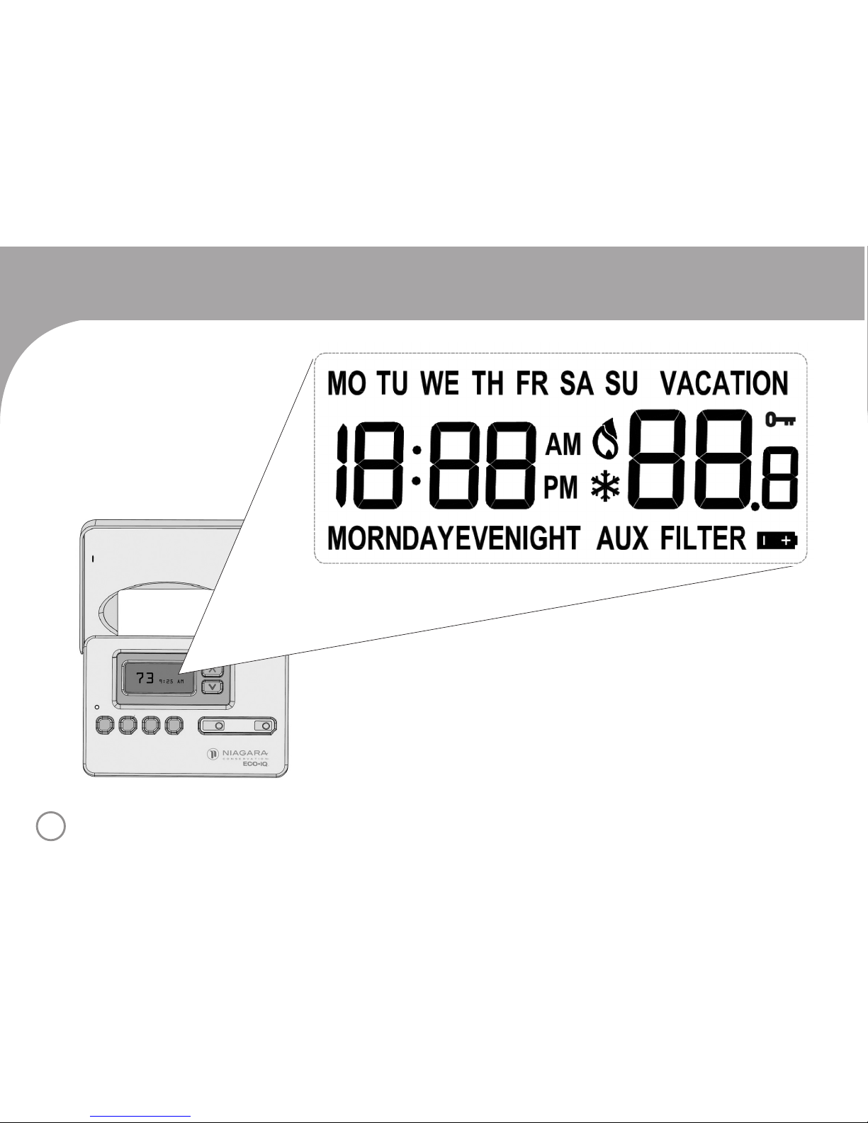
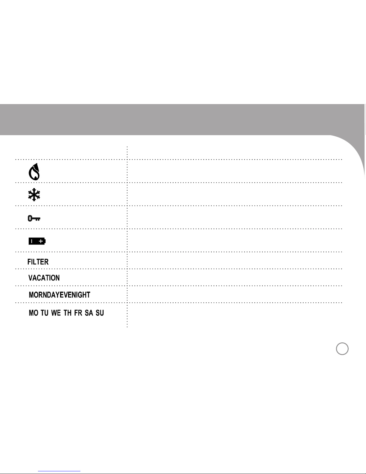
LCD DISPLAY
ICON INDICATES
Heating system is being activated
A/C cooling system is being activated
Key Lock mode is activated
Battery levels
Change lter reminder
Vacation mode
Indicates timeframe of current day (Morning, Day, Evening, Night)
Indicates day of week (Monday, Tuesday, Wednesday, Thursday, Friday,
Saturday, Sunday)

10
TESTING THE NEW THERMOSTAT
WARNING!
• Do not switch the system to cool if the outdoor temperature is below 50°F (10°C). This may damage the cooling
system and may cause personal injury.
• This thermostat is equipped with automatic compressor protection to prevent damage due to short cycling.
The short cycle protection provides a 5-minute delay between heating (heat pump models) or cooling cycles
to prevent the compressor from being damaged.If the Heat/Cool icon is ashing, this indicates the system is
in the delay period.
1. Restore the system power. The LCD (liquid crystal display) will
alternately display the time and room temperature. The LCD will
illuminate at the touch of the red or blue arrow keys. LCD will
return to its normal state after 10 seconds.
2. Set the fan switch to the ON position. The system blower
should start.
3. Set the fan switch to the AUTO position. The system blower
should stop.
4. Set the system switch to the HEAT position and depress the red
arrow key until the temperature set point is at least 3 degrees
above the room temperature. The LCD will display a ame icon
to indicate the thermostat is activating the heating system. The
system should start within several seconds (the system blower
may not come on immediately).
INSTRUCTIONS
Image shows display altering between time and a
room temperature of 70°
Image shows room temperature of 71° and Heat set
point of 75° as the display alternates every 3 seconds.

11
5. Set the system switch to the OFF position. The system should
shut down within several seconds. The LCD will again alternately
display the time and room temperature.
6. Set the system switch to the COOL position and depress the
blue arrow key until the temperature set point is at least 3
degrees below the room temperature. The LCD will display a
snowake icon to indicate the thermostat is activating the A/C
system. The cooling system should start within several seconds.
WARNING: Do not perform this test if the outdoor temperature
is below 50°F.
7. Set the system switch to the OFF position. The system should
shut down within several seconds. The LCD will again alternately
display the time and room temperature.
INSTRUCTIONS
PROGRAMMING & OPERATING THE NEW THERMOSTAT
Setting the Time & Day
1. With the thermostat in set at either COOL, OFF, or HEAT, depress the TIME/DAY key. The hour will ash.
Using the red/blue arrow keys, set the correct hour.
2. Depress the TIME/DAY key a second time. The minutes will ash. Using the red/blue arrow keys, set the
correct minutes.
3. Depress the TIME/DAY key a third time. The day will ash. Using the red/blue arrow keys, set the correct
day. The display will stop blinking after 15 seconds and the time and day settings will be stored.
Image shows room temperature of 76° and A/C set
point of 73° as the display alternates every 3 seconds.

12
SETTING THE HEATING & COOLING PROGRAMS
The thermostat includes a factory set program that will adjust the temperature 4 times per day (MORN, DAY, EVE,
NIGHT) Monday through Friday and Saturday/Sunday. This program can be customized using the steps below.
Factory Set Program
PROGRAM SYSTEM Monday - Friday Saturday, Sunday
MORN Heat 6:00a: 68°F (20°C) 6:00a: 68°F (20°C)
Cool 6:00a: 78°F (26°C) 6:00a: 78°F (26°C)
DAY Heat 8:00a: 60°F (16°C) 8:00a: 60°F (16°C)
Cool 8:00a: 85°F (29.5°C) 8:00a: 85°F (29.5°C)
EVE Heat 4:00p: 68°F (20°C) 4:00p: 68°F (20°C)
Cool 4:00p: 78°F (26°C) 4:00p: 78°F (26°C)
NIGHT Heat 10:00p: 60°F (16°C) 10:00p: 60°F (16°C)
Cool 10:00p: 82°F (28°C) 10:00p: 82°F (28°C)
INSTRUCTIONS

13
CUSTOMIZING THE PROGRAM
1. Set the System switch to the HEAT or COOL position and the Fan switch to either the AUTO or ON position.
NOTE: In AUTO, the system blower will run only when the A/C or heat is running. In ON, the system blower will
operate continuously.
2. Depress the PROGRAM key. LCD will display an image similar to the following.
The set point temperature will blink and the time will be displayed.
3. Use the red/blue arrow keys to select the set point temperature for the Morning program Mon – Fri.
4. While the temperature is still blinking, press the TIME/DAY key to set the time for the Morning program. The time in
the LCD will blink. Use the red/blue arrow keys to select the correct time.
5. Set the remaining Day, Evening, and Night times and temperatures for the Mon – Fri. and Sat/Sun periods:
• Depress the PROGRAM key to select the desired period.
(Each depression of this key cycles the menu to the next period.)
• Depress the Time/Day key to switch between time settings and temperature settings at each period.
• Use the red/blue arrow keys to increase/decrease the time and temperature settings.
• The settings are automatically stored 15 seconds after the last touch of a key. NOTE: If the programming at any
period is not completed and the display stops blinking, depress the PROGRAM key as necessary to cycle back
to the desired period to be programmed.
• This procedure is required for both the COOL and HEAT system settings
INSTRUCTIONS
Set point temperature blinking.

14
TEMPORARY HOLD
1. Use the red/blue arrow keys to temporarily raise or lower the set point temperature at any time during normal
operation. The temperature will hold at the new level UNTIL the next program period begins at which point the
thermostat will return to the program temperature.
NOTES: To view the time remaining on vacation hold, depress the VACATION key at any time. To return the thermostat
back to normal program mode at any time, depress the RUN key for 1 second.
VACATION HOLD
1. The thermostat can be set to hold a single specic temperature for
up to 30 consecutive days. Upon activation, the thermostat will hold
the temperature until the duration period times out at which point the
thermostat will return to program mode. To activate this feature, depress
the VACATION key. The LCD will display the duration in days and the
set point temperature.
2. Use the red/blue arrow keys to adjust the set-point temperature to the
desired level.
3. Depress the TIME/DAY key to select the duration of the hold period (up
to 30 days). After 10 seconds from the last touch of a key, the thermostat
will store the setting and the LCD will return to its normal setting.
INSTRUCTIONS
Image shows day1
holding at 73°F
Image shows day25
holding at 71°F

15
CHANGE SET TEMPERATURE
1. The system switch must be set to COOL or HEAT to adjust the set temperature.
2. If the or key is pressed once and released, the set temperature will increase or decrease by one degree.
Press and hold the or key to scroll to desired temperature and release.
3. Changing the set temperature automatically puts the thermostat in Temporary hold.
4. Changing the set temperature does not affect the programmed Temporary or Vacation hold.
INSTRUCTIONS
KEY LOCK FEATURE
Setting the Key Lock
Follow the steps below to set a 3-digit passcode to lock or unlock the thermostat.
1. Press and hold the UP and DOWN keys at the same time for 3 seconds to enter the Key Lock Setting mode.
2. “- - -“ will appear on the LCD with a ashing “key” icon.
Press the UP or DOWN keys to select the rst digit [e.g. “3 - -”], then press PROG to move to the next digit
and repeat until your 3-digit code is displayed. To change a digit, press PROG to cycle through.
3. Press RUN to save. The 3-digit code ashes twice, remains on the screen for 2 seconds and then returns to
normal time mode.
Key Lock Setting mode
with ashing key icon.

16
Disable or Resetting the Key Lock
To disable the Key Lock feature or change the code, the user must disable the LOCK rst.
1. Press and hold UP and DOWN key together for 2-3 seconds to enter Key Lock Setting mode
2. “- - - “ will appear on the LCD with “lock” icon ashes
3. Enter the 3-digit code created to lock the thermostat. Press the UP or DOWN keys to select the rst digit, then press
PROG to move to the next digit and repeat until your 3-digit code is displayed.
4. If the code matches, the key will be unlocked and the code “ - - -” ashes twice and remains on the screen for 2
seconds and then returns to normal time mode. If the code does not match, the wrong input code will remain for 2
seconds without ashing.
5. The universal code to unlock is “5 5 5”. This can be used to unlock any 3-digit code and resets the key lock
feature.
UNDERSTANDING ADDITIONAL FEATURES
• Advanced Recovery Mode: This feature minimizes the time required to achieve a comfort setting after set back
period. During normal operation, the thermostat will gradually change to the set point temperature prior to the
actual program time. Advanced Recovery Mode ensures that the room is at the desired temperature at the desired
time by intelligently initiating the temperature adjustment in advance. Note: This feature can be deactivated by
changing the ARM switch on the circuit board to off.
• High Temperature Protection: While in the HEAT position, if the room temperature reaches 93°F (34°C), the
thermostat will automatically shut off. In the unlikely event the room temperature reaches 99°F (37°C), a mechanical
bimetal switch will shut off the thermostat.
INSTRUCTIONS
17
• Low Temperature Protection: While in the HEAT position, if the room temperature drops below 40°F (4°C), the
thermostat will automatically initiate a call for heat.
• Compressor Protection: To protect the system compressor(s) from damage, the thermostat features a 5-minute
delay. After the cooling system (or heat pump turns off), the thermostat will not allow it to re-start until the 5 minute
delay expires. A blinking snowake/ame indicates this feature has been activated. Once the 5 minute delay
expires, the snowake/ame will illuminate continuously and the system will be able to re-start when called upon.
NOTE: For the purpose of unit installation, this delay can be overridden by depressing the RESET button. This will
erase any programmed settings.
• System Reset: The thermostat can be reset to factory software settings including the program. All user entered
settings will be lost. The reset will also override the 5 minute compressor protection feature. To reset the thermostat,
gently press the reset button on the front panel using a paper clip or similar small pointed object.
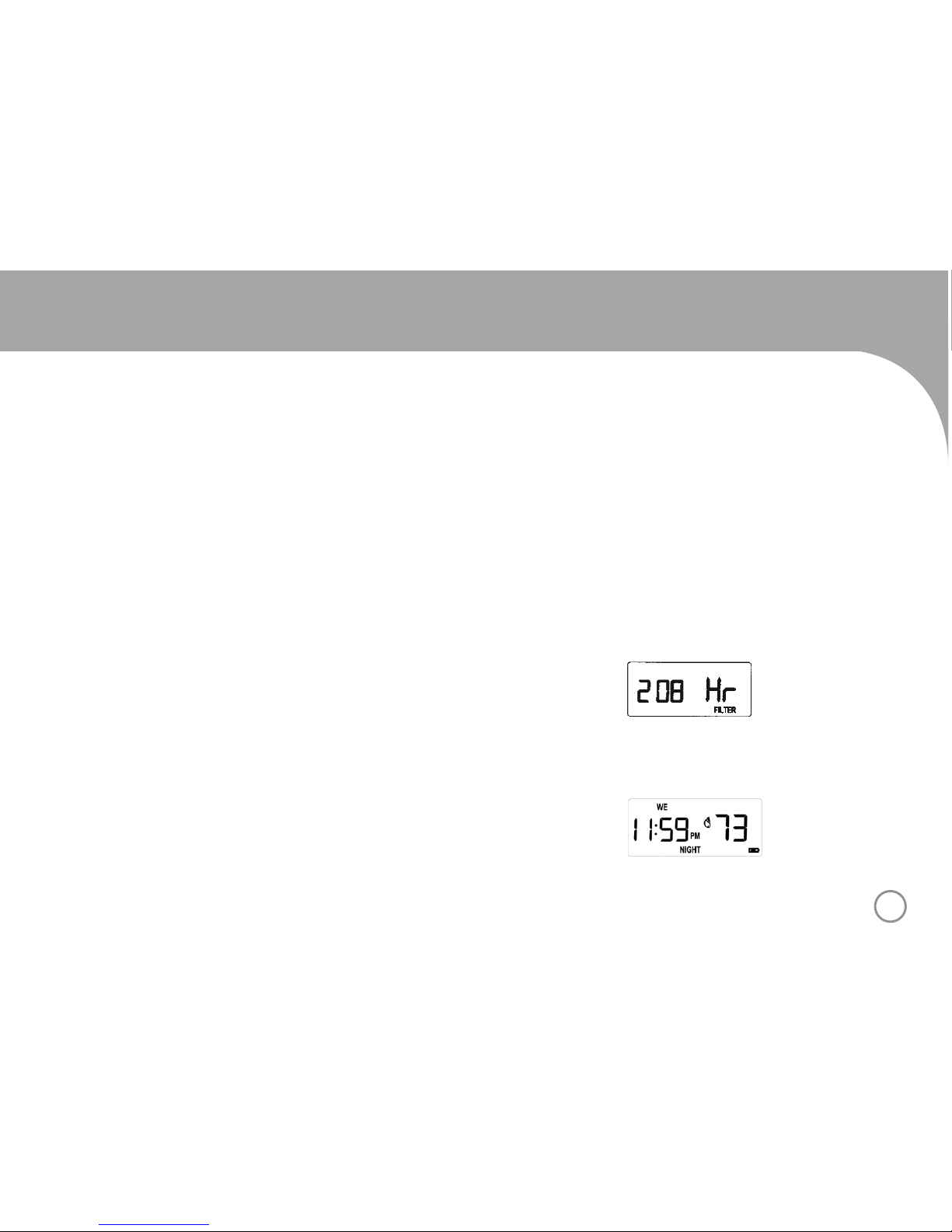
• Filter Change Reminder: The thermostat features a reminder for the
user to change the heating/cooling system lter(s). When the system fan
is operating, the internal thermostat timer is activated. When the timer
reaches 500 hours, the lter icon will appear in the LCD. To view the time,
depress the PROGRAM and RUN keys simultaneously. The time in hours
will be displayed. To reset the lter icon from this position, depress and
hold the PROGRAM key for 3 seconds. The counter will reset to 000 Hr.
• Low-Battery Detection: Battery voltage is sampled every 4 seconds.
When the battery voltage drops to a certain level, the low battery warning
will appear.
FEATURES
Image shows the lter counter at 208
hours. The lter icon illuminates in the
primary display at 500 hours.
Image shows battery icon appears
in lower right corner of display.

18
TROUBLESHOOTING
SYMPTOM CORRECTIVE ACTION
Display is Blank Check thermostat wiring & connections.
Check circuit breaker/fuse panel.
No heat Set system switch to HEAT and raise set point above room temperature.
If ame icon is blinking, allow the 5 minute compressor lock-out to expire. Check
thermostat wiring and connections. Check pilot light or HSI system on furnace.
No Cool Set system switch to COOL and lower set point below room temperature.
If snowake icon is blinking, allow the 5 minute compressor lock-out to expire.
Check thermostat wiring & connections.
System turns on/off too
frequently or not enough
Adjust the differential setting on the thermostat.
A high differential decreases cycle rate and a low differential increases cycle rate.
Display is not illuminated Touch the up or down arrow key. Display will illuminate for 10 seconds.
Room temperature and
set point disagree
Normal (depending on differential setting). Check for drafts that could quickly
change the room temperature before the system is able to correct it.
System fan runs
continuously
Set fan switch to AUTO. Check thermostat wiring & connections.
19
TROUBLESHOOTING
SYMPTOM CORRECTIVE ACTION
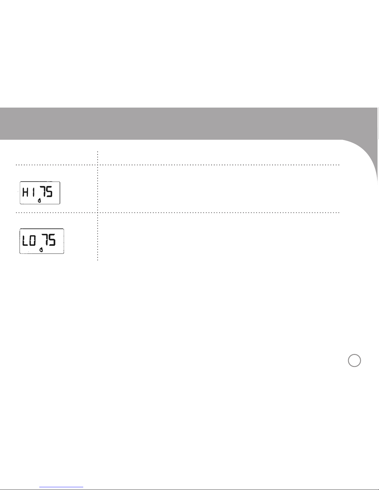
‘HI’ is displayed Reduce room temperature or allow a newly installed thermostat to acclimate.
HI indicates a room temperature reading greater than 90°F (32°C).
‘LO’ is displayed Increase room temperature or allow a newly installed thermostat to acclimate.
LO indicates a room temperature reading less than 45°F (7°C).

20
WIRING DIAGRAMS
TERMINALS
Terminal
Non-Heat Pump
4-wire System*
Non-Heat Pump
5-wire System
2-wires millivolt
Heat System
Single Stage Heat
Pump System*+
RC— Cooling 24VAC — —
RH24VAC Heating 24VAC Millivolt Heating 24VAC
C24VAC Common 24VAC Common Transformer Common 24VAC Common
GFan Fan — Fan
YCooling Cooling — Compressor
WHeating Heating Millivolt Heating —
B—— —Reverse Valve
(heat energized)
O———Reverse Valve
(cool energized)
*Connect RCand RH+Connect W and Y (user supplied)
Table of contents
Other Niagara Thermostat manuals


