NIBE-BIAWAR HK 200M User manual
15.02.2017
25957
HK 200M
Installation manual
Indoor unit
cooperating with air
heat pumps
HK 200M
HK 200M
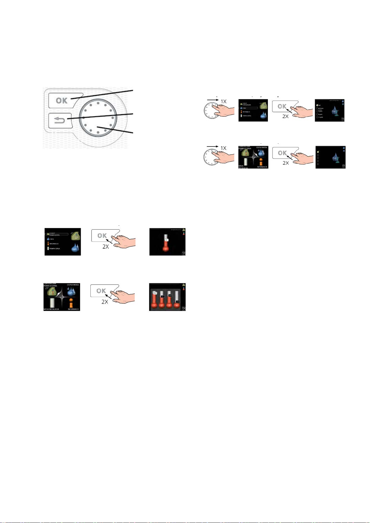
Navigation
Room temperature setting
Detailed description of button functions to be found in
section Display.
Moving about the menu and inputting various settings
has been specied in the Menu Selection section.
The room temperature setting mode is selected by
pressing the OK button twice from the start mode lev-
el in the main menu. More information to be found in
section Room temperature setting.
SMO 20
SMO 40
In order to temporarily increase hot water volume rst
turn the control knob to mark menu 2 (icon present-
ing water drop) and press the OK button twice. More
information to be found in section Setting hot water
output
If there are any distortions to the heat comfort, before
contacting the installation technician, you can per-
form some activities yourself.Appropriate instructions
can be found in section Cancelling the settings.
Increase hot water volume
If the heat comfort is distorted
Ok button
(conrm/select)
Back Button (back/
cancel/exit)
Regulation knob
(move/increase/decrease)
Abbreviated manual
SMO 20
SMO 40

3List of contents |HK 200M
List of contents
1 Important information _______ 4
Safety information4
2 Supply and handling ________ 6
Transport ______________________________ 6
Assembly ______________________________ 6
Supplied elements _______________________ 6
Cover removal __________________________ 6
3 Construction of the internal mod-
ule _________________________ 7
4 Pipe connections ___________ 9
General information ______________________ 9
Dimensions and pipe connections __________ 12
Connection of inner unit__________________ 13
Connection options______________________ 15
5 Electrical connections ______ 16
General information _____________________ 16
Connections___________________________ 17
Settings ______________________________ 24
6 Start-up and regulation _____ 25
Preparations___________________________ 25
Filling and venting ______________________ 25
Start-up and acceptance _________________ 26
7 Control __________________ 27
Display _______________________________ 27
System menu__________________________ 27
8 Maintenance service _______ 28
Servicing activities ______________________ 28
9 Distorted heat comfort______ 29
10 Accessories _____________ 29
11 Technical data____________ 30
Dimensions and layout of connections ______ 31
Technical data _________________________ 31
Diagram of electrical connections __________ 32
4HK 200M
1 Important information
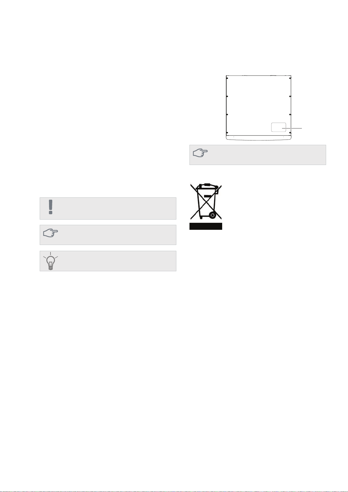
Information regarding
safety Serial number
Symbols
Marking
HK 200M features the CE mark and re protection
IP21.
The CE mark con rms that NIBE-BIAWAR has taken
care for product conformity with applicable regula-
tions of relevant EU Directives. The CE is required
for most products sold in the EU, regardless of their
place of manufacture.
IP21 means that items with the diameter greater or
equal to 12.5 mm cannot permeate inside causing
damage, and that the product has been secured
against vertically falling water drops.
The device can be operated by children aged over
8 and persons with physical, sensory, or mental dis-
abilities, and without any experience or knowledge
about its operation, if supervised or trained in safe
operation, and if they understand the risks related
to its operation. The device must not serve as a toy
for children. Activities related to cleaning and basic
maintenance must not be performed by unsupervised
children.
Rights to introduce structural changes reserved.
©NIBE-BIAWAR 2016
This manual contains installation and maintenance proce-
dures for specialists.
The serial number is located at the top of HK 200M.
IMPORTANT
This symbol informs about the risk to the device or a
person
CAUTION
This symbol points to important information to be not-
ed when operating the device.
ADVICE
This symbol shall mean tips to make product operation
easier.
CAUTION
When contacting the installation technician, always
provide the product serial number (14 digits).
Serial
number
Waste disposal
Information for particular countries
Disposal of the packaging shall be the
responsibility of the installation techni-
cian installing the product, or a special
waste management facility.
Incorrect disposal of the product by the user is sub-
ject to administrative penalties under applicable reg-
ulations.
Installation manual
This installation manual must be submitted to the Cli-
ent.
Do not dispose of decommissioned prod-
ucts together with regular household
wastes. Hand them over to a specialist
facility.
dealing with waste disposal or salesperson offering
such services.
Chapter 1 | Important information

5HK 200M
Description Notes Signature Date
Heating medium
Installation rinsing
Installation venting
Diaphragm expansion vessel
Particulate lter
Safety valve
Cut-off valves
Pressure in the heating system
Connection according to the
drawing
Hot water
Cut-off valves
Mixing valve
Safety valve
Power supply
Communication connection
Circuit fuses
Fuses,
internal module
Building fuses
temperature sensor
outdoor
Room sensor
Energy meter
Emergency switch
Switch
differential
Thermostat emergency mode
setting
Miscellaneous
Connected to
Installation acceptance
The heating system must be accepted before start-up. Acceptance must be done by a person with appropriate
qualications. Complete the card in the operating manual by entering the installation data.
Checklist
Chapter 1 | Important information

6HK 200M
2 Supply and operation
Transport
Assembly
HK200M indor device must betransportedandstored
vertically in a dry place. HK 200M can be, however,
carefully placed on the rear side of the casing when
carrying the device into the building.
Leave 800 mm free space at the front of the mod-
ule. All maintenance works on HK 200M can be done
from the front.
Side covers are installed for permanent, therefore,
they cannot be disassembled.
• HK 200M must be set on a solid waterproof base
that would keep the weight of the indoor unit. The
regulated legs of the heat pump allow for levelling
and stable setting of the device.
• Because HK 200M is equipped with condensate
drain, the installation site of the indoor module
must be furnished with a oor drain with a dis-
charge to the sewer system. 1. Remove screws at the bottom edge of the front
cover.
2. Tilt the cover at the bottom edge and lift.
Installation site
IMPORTANT
Leave 10 – 25 mm free space between the indoor
module and the back wall for cables and piping.
800 mm
Cover removal
1
2
Chapter 2 | Supply and operation
20-40 mm
Elements supplied
Safety valve
with a manometer
Wrench size 13
7HK 200M
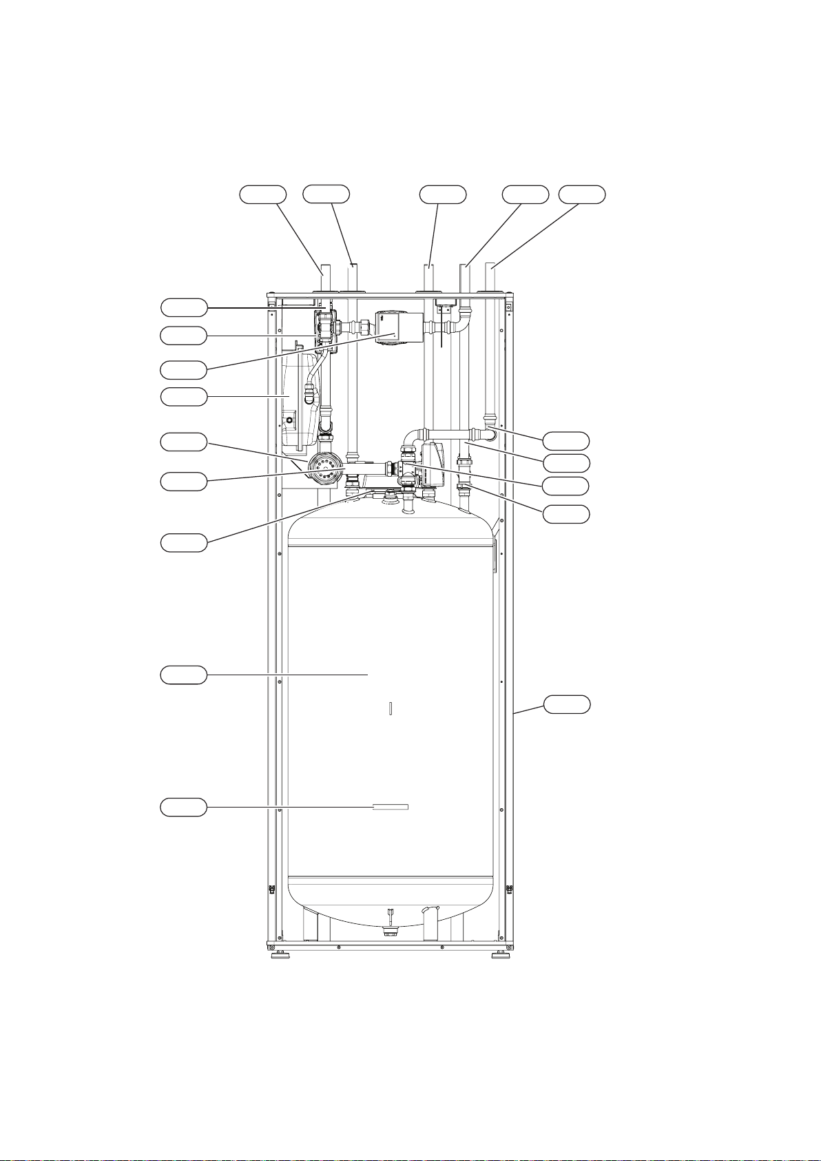
3 Indoor module structure
Chapter 3 | Indoor module structure
HK 200M
EB2
XL11
QN12
QN10
GP12
CM1
EB1
XL3 XL8
XL4 XL1
EB15
BT71
BT6
BT64
BT63
BT7
BT25
BT3

8HK 200M
EMERGENCY
Brown
Black
N
PWM
GND
K1
K2
K3
L
N
PE
BT64 BT63 BT25 BT71BT6
GP12
X1 X2
GP12
L
N
PE
PE
L3
L2
L1
L
N
SMO 400V 3N AC 50Hz
QN12
Brown
Black
N
QN10
BT7
F1
LEGEND
X1 X2
Chapter 3 | Indoor module structure
K1-K3
T1
X3
AA8
F3
Pipe connections
XL1 Connection, heating medium, supply
XL3 Connection, hot water
XL4 Connection, cold water
XL8 Connection, supply of the heating medi-
um from the external unit
XL11 Connection, safety group,
manometer
HVAC elements
CM1 Diaphragm expansion vessel, closed,
heat medium
QN10 Isolation valve, domestic hot water / cen-
tral heating
QN12 Isolation valve, cooling/heating
GP12 Circulation pump
Sensors
BT3 Temperature sensor, heating medium re-
turn
BT6 Temperature sensor, hot water loading
BT7 Temperature sensor, top of the hot water
heater
BT25 Temperature sensor, heating medium
supply
BT63 Temperature sensor, heating medium
supply downstream the submersible heat-
er
BT64 Temperature sensor, cooling medium
supply
BT71 Temperature sensor, heating medium re-
turn
Electrical elements
X1 Terminal block for low
voltage
X2 Terminal block for low
voltage
X3 Terminal block for high
voltage
K1-K3 Submersible heater contact
T1 Thermostat, standby mode
AA8 Titanium anode card
F3 Temperature limiter
F1 Circuit breaker
EB1 Submersible heater
Miscellaneous
EB15 HK 200M
PF3 Serial number
EB2 Hot water tank

9HK 200M
4 Pipe connections
General information
The piping installation must be executed according to
the applicable standards and directives.
HK 200M indoor unit, with NIBE Monoblock outdoor
air heat pump, and NIBE SMO controller form a com-
plete heating system.
The system can cooperate with a low- and medi-
um-temperature heating system. Recommended
temperature of the heating medium at minimum de-
signed outdoor temperature DOT must not exceed
55°C on supply, and 45°C on return circuit from the
heating system, whereas HK 200M can achieve even
65°C when using a ow-through heating module or
another peak heat source.
Excess medium owing out of the safety valve must
be discharged via a pipe to a oor drain. The over-
ow pipe must be slanted at the entire length from the
safety valve, and must be secured against freezing.
In order to achieve maximum system efciency, we
recommend the installation of HK 200M as close to
the heat pump as possible.
The HK 200M module is not equipped with cut-off
valves, which must be installed outside the indoor
module to make future maintenance easier. The HK
200M module can be connected to the central heat-
ing, cooling, and domestic hot water installation. In-
stall the supplied safety valve and the manometer.
HK 200M is equipped with a diaphragm expansion
vessel for a heating circuit of 10 I. Initial pressure of
the expansion vessel must be set appropriately to
the maximum height (H) between the vessel and the
highest heater, see the drawing. The initial pressure
of 0.5 bar (5 mvp) shall mean maximum permissible
height difference of 5 m.
If the standard initial pressure in the diaphragm ex-
pansion vessel is too low, it can be raised by lling the
vessel through the valve installed.
Any change to the initial pressure affects the dia-
phragm expansion vessel’s capacity to support the
increase in water volume.
IMPORTANT
All places in the heating system located high must be
equipped with vents.
IMPORTANT
Pipelines must be rinsed before connecting the indoor
module so that possible dirt does not damage its ele-
ments.
IMPORTANT
As long as heating circuits in the system have not been
led with the heating medium, do not set the switch
(SF1) in the SMO module in position “I” or “ ”. The
compressor in the heat pump and the ow-through
heating module can be damaged.
Capacities of the indoor unit and the
heating system
System requirements
The inner capacity of HK 200M for the purposes of
calculating the diaphragm expansion vessel in the
domestic hot water installation totals 180 l. The ca-
pacity of the diaphragm expansion vessel must con-
stitute at least 5% total capacity.
Minimum required conguration:
In order to assure correct operation, the capacity of
the heating system must meet the requirements for
the installation. If this condition has not been met, in-
stall an additional buffer tank. (NIBE UKV).
CAUTION
In this case a diaphragm expansion vessel of the
DHW installation must have the capacity of 10l. The
diaphragm expansion vessel at the domestic hot water
installation is not required. It is, however, required to
install a safety valve with opening pressure of 6 bar.
IMPORTANT
All connections require free ow, hence a discharge
valve must be installed.
Chapter 4 | Pipe connections
10 HK 200M
P
P
HK 200 S
HK 200 M
P
The HK 200M indoor unit is equipped with a coil water
heater, diaphragm expansion vessel , safety group,
electric heater, isolation valves, plate heat exchang-
er, metering instruments, and an electronic circulation
pump. Together with the heat pump NIBE Monoblok
and NIBE SMO module, it forms a complete heating
system.
The F2030, F2040 8 kW; F2040 12 kW, F2120 8
kW; F2120 12 kW, F2120 16 kW outdoor unit pro-
vides heat for heating the domestic hot water and
supplying the heating system while using free ener-
gy in the outdoor air, efciently operating within the
range of low temperatures up to -20°C.
The connection of the outdoor unit and indoor unit
HK 200M with a system of pipes lled with a cooling
medium secures the connection against freezing in
the event of any power outages. The control of sys-
tem operation is the function of SMO 20 or SMO 40
module.
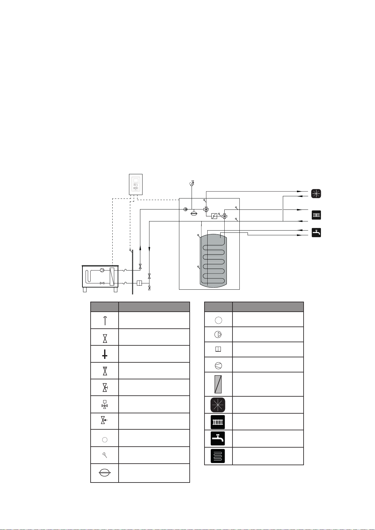
Installation diagram
Chapter 4 | Pipe connections
Symbol Meaning
Vent
Cut-off valve
Water tap
Non-return valve
Balancing valve
Three-way valve
Safety valve
Thermometer
Temperature sensor
Diaphragm expansion
vessel
T
P
T
P
T
P
T
P
T
P
T
P
T
P
T
P
T
P
T
P
Symbol Meaning
Manometer
Circulation pump
Particulate lter
T
P
Compressor
T
P
Heat exchanger
Cooling
Central heating system
Domestic hot water
Heating systems
Floor heating
T
P
T
P
T
P
T
P
T
P
T
P

11HK 200M
Indoor HK 200M module
• It is recommended that the HK 200M module
should be installed in a room with a oor drain, at
best in a utility room or a boiler house.
• The oor must be solid, concrete at best.
• The HK 200M module must be set with its back
to the outer wall, at best in a room where noise is
not a problem. If possible, do not place the device
near a wall of a bedroom or another room where
noise might be a problem.
• The device can be leveled using regulated legs.
• Pipes must be led in such a way that they are not
adjacent to the bedroom or living room.
• Remember to leave about 800 mm free space at
the front and 500 mm over the device to provide
for future maintenance.
1. Connect HK 200M module to the heating system,
cold, and hot water pipelines.
2. Use hydraulic connections to connect the outdoor
and indoor unit.
3. Connect the current meter, outdoor temperature
sensor, centralized current control, and cables
between HK 200S, AMS 10 and SMO 20/40.
4. Connect power supply to module HK 200M.
5. Proceed according to start-up instructions in
chapter Start-up and regulation.
Recommended order of assembly
Chapter 4 | Pipe connections

12 HK 200M
Dimensions and pipe connections
Chapter 4 | Pipe connections
20-40
1600 95
XL11
XL10
XL3 XL5 XL4 XL2 XL1
XL9
XL8
PF3
300 155
45
95 90
120
85 65 55
600
610
315
70
Pipe connections
XL1 Connection, Heating medium supply
Ø22 mm
XL2 Connection, Heating medium return
Ø22 mm
XL3 Connection, hot water Ø22 mm
XL4 Connection, cold water Ø22 mm
XL5 Connection, circulation Ø15 mm
XL8 Connection, supply of the heating medi-
um from the external unit Ø22 mm
XL9 Connection, discharge of the heating me-
dium to the external unit Ø22 mm
XL10 Connection, cooling Ø22 mm
XL11 Connection, safety group
Ø22 mm, manometer
Other information
PF3 Serial number plate
65
13HK 200M
Compatible heat pumps
air/water by NIBE with module
HK 200M
Connection of the heating system
HK 200M indoor module can cooperate with Mono-
blok type outdoor units.
Compatible NIBE Monoblok heat pumps include:
An external heat source, e.g. a gas or oil boiler, can
be connected to (XL1) (input) and (XL2) (output) at
HK 200M.
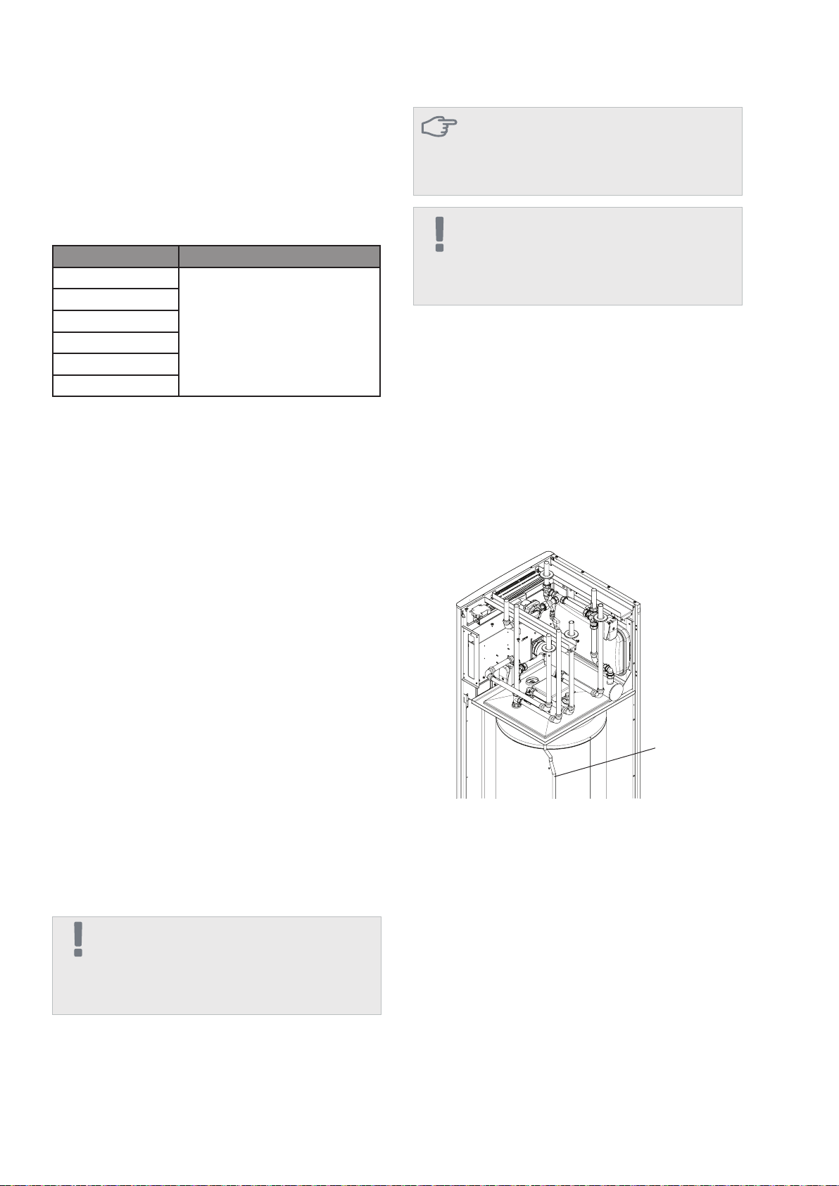
The HK 200M module over the domestic hot water
tank features a drain tray from where condensate
is discharged via a hose. The hose drains all con-
densate away from the device to minimize the risk
of damage. If necessary, the hose can be extended.
Condensate
hose
Pipe connections of the heating system are to be
made at the top.
• All the required protections and cut-off valves
must be installed as close to the HK 200M mod-
ule as possible.
• Where necessary, install the vents.
• Safety valve with a nanometer at the central heat-
ing circuit and the safety valve at the hot water
system must be installed on relevant conductors
XL 11 and XL 4. In order to prevent ooding,
safety valve must be equipped with an over ow
pipe. The over ow pipe must be slanted at the
entire length from the safety valve, and must be
secured against freezing.
• When connecting to the installation where all
heaters have been equipped with thermostat
valves, install a discharge valve or remove sever-
al thermostats to assure appropriate ow.
IMPORTANT
The term “heating system”, as used in this installation
and operation manual, shall mean the heating or cool-
ing system supplied with a hot or cold medium from
the HK 200M module for heating or cooling purposes.
Connecting an external heat source
Condensate elimination
More information to be found at www.nibe.eu and
in relevant installation manuals for accessories used.
ChapterAccessories can serve to check the list of ac-
cessories to be used with HK 200M.
Chapter 4 | Pipe connections
Symbol Application
F2030
all versions
F2040 8 kW
F2040 12 kW
F2120 8kW
F2120 12kW
F2120 16kW
Connection of indoor unit
IMPORTANT
It is permitted that between the safety valve installed
on the pipe supplying cold water and XL4 connection,
there is a T-pipe with a drain valve and a T-pipe with a
diaphragm expansion vessel.
CAUTION
Directly on the pipe supplying cold water to the hot
water tank, safety valve must be absolutely installed
with opening pressure of 6 bar, which would protect
the tank against excessive pressure increase.

14 HK 200M
• The outdoor unit can be connected to the indoor
unit according to one of the system solutions to
be downloaded from website www.nibe.eu.
• The part of the outdoor unit with the indoor unit
that remains outdoors must be made using exi-
ble hoses supplied with the outdoor unit.
• We should install other elements supplied with
the outdoor unit.
• All outdoor pipes must be thermally insulated with
a pipe lining with at least 20mm thickness.
• Install cut-off and drain valves to allow for emp-
tying the outdoor unit in case of long power out-
ages.
• The supplied exible hoses act as vibration ab-
sorbers. Flexible hoses must be installed to form
elbows that would attenuate vibrations.
Connection between the outdoor and in-
door unit
Chapter 4 | Pipe connections
IMPORTANT
If the supply pump is controlled from the outside, it
must work even if the outdoor unit does not operate, to
prevent damage as a result of freezing.

15HK 200M
Connection to the heat pump
Connection when operating without a
heat pump
Connection of hot and cold water
All outdoor pipes must be thermally insulated with a
pipe lining with at least 20mm thickness.
HK 200M is not equipped with cut-off valves, which
must be installed outside the indoor module to make
future maintenance easier.
When connecting to the installation where all heaters/
oor heating pipes have been equipped with thermo-
stat valves, in order to assure appropriate ow, install
a discharge valve or a buffer in the parallel layout, or
remove several thermostats.
Connect the input pipe from the heat pump (XL8) to
output pipe XL9 of the heat pump.
The installation of the mixing valve is necessary
if factory settings are changed in a way where the
temperature can exceed 60°C. When changing the
factory settings, follow the national regulations in this
respect. The setting is entered in menu 5.1.1.
Connection of the heating system
The system can be extended by additional circuits ac-
cording to the capacity of the applied control module:
SMO 20 or SMO 40.
Additional accessories, capacity and connection
method have been specied in the manual for SMO
20 and SMO 40, in chapters Accessories and Elec-
trical connections.
Cooling system connection
Cooling is controlled by sensor BT64 and isolation
valve QN12. If cooling is needed, the isolation valve
changes the direction, and opens from the cooling
circuit side.
Optional connections
Chapter 4 | Pipe connections
P
P
P
P
P
HK 200 M
Connection options

16 HK 200M
5 Electrical connections
General information
The entire electrical equipment, apart from outdoor
temperature sensors, room sensors, and current in-
tensity meters, has been connected according to fac-
tory settings.
• Disconnect the indoor module before performing
tests of electrical system insulation in the build-
ing.
• If the building is equipped with a differential
switch, HK 200M must be equipped with a
separate switch.
• The diagram of indoor module connections can
be found in section „Diagram of electrical connec-
tions”.
• Do not lay communication and signal cables to
external contacts near high-voltage cables.
• Minimum cross-section of communication and
signal cables to external contacts must total 0.5
mm² with the length of up to 50 m, for example
EKKX or LiYY, or similar.
• Minimum cross-section of power supply cables
must total 0from 2.5 mm² to 4 mm².
• For cabling in HK 200M, use cable passes UB1
and UB2 (as marked in the drawing). In UB1 and
UB2, cables are input through the entire indoor
module from the back wall towards the front wall.
IMPORTANT
As long as the heating circuits have not been lled with
the heating medium, and if the central heating system
has not been vented, the switch (SF1) in SMO cannot
be set in positions „I” or „ ”. Otherwise, the tempera-
ture limiter, thermostat and ow-through heater can be
damaged.
X1 Terminal block for low
voltage
X2 Terminal block for high
voltage
X3 Terminal block for high
napięcia
K1-K3 Submersible heater contact
T1 Thermostat, standby mode
F3 Temperature limiter
AA8 Titanium anode card
F1 Circuit breaker
UB1 Cable pass
UB2 Cable pass
F3-SF2 Reset
X1
X2
LEGEND
Chapter 5 | Electrical connections
K1-K3
T1
X3
F1
AA8
F3
UB2 UB1
IMPORTANT
The electrical installation and maintenance service
must be performed under the supervision of a quali ed
power technician with relevant quali cations. Before
starting any maintenance works, power supply must
be cut off using an automatic switch. The electrical in-
stallation and cabling must be executed according to
applicable regulations.
IMPORTANT
If the power supply cable is damaged, it can only be
replaced by authorised service, its technician, or other
quali ed person, to avoid danger or damage.
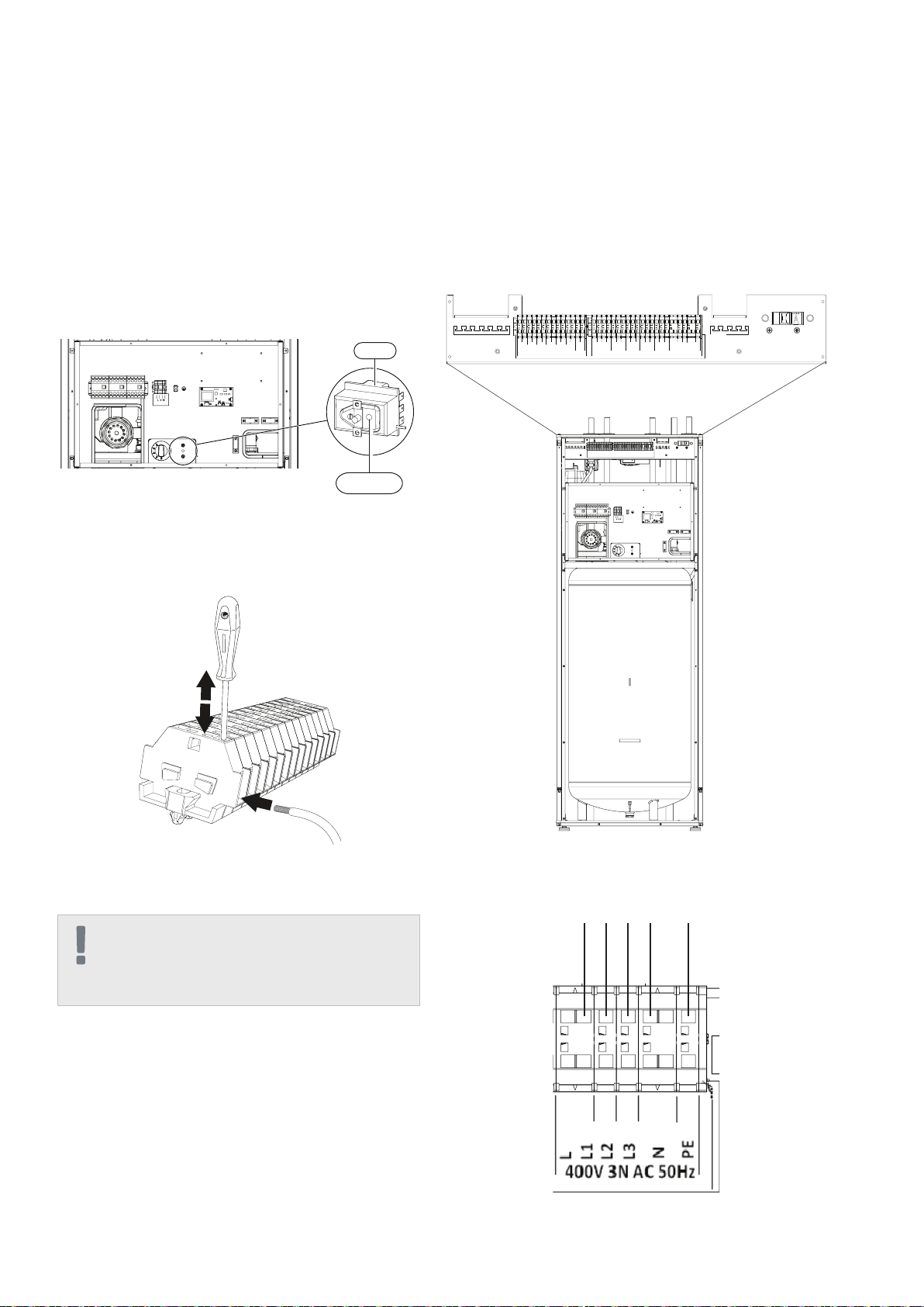
17HK 200M
Temperature limiter (F3) is accessible behind the front
cover. Temperature limiter is reset by strong press-
ing of the button (F3-SF2) using a small screwdriver.
Press the button, max. 15 N (approx. 1.5 kg).
Resetting
Cable blockade
Use an appropriate tool to release/block cables in the
internal module clamps.
The power supply is to be connected to clamp (X2)
via the input at the back of the unit. The cable must be
dimensioned according to the applicable standards.
HK 200M must be connected to the power supply 400
V 3N AC 50Hz as speci ed on the clamp (X2).
Connection
Connections
IMPORTANT
In order to prevent interferences, do not lay unshielded
communication and/or signal cables to external con-
tacts at the distances lower than 20 cm from high-volt-
age cables.
Power supply connection
Temperature limiter
Temperature limiter (F3) cuts off the power supply of
the electrical heating module if the temperature in-
creases to the range of approximately 87 °C, and can
be reset manually.
F3
F3-SF2
L1 L2 L3 NPE
Circuit breaker
The system for automatic regulation of the heating,
circulation pump, and their cabling at HK 200M are
secured internally with a circuit breaker (F2).
Chapter 5 | Electrical connections
EMERGENCY
Brown
Black
N
PWM
GND
K1
K2
K3
L
N
PE
BT64 BT63 BT25 BT71BT6
GP12
X1 X2
GP12
L
N
PE
PE
L3
L2
L1
L
N
SMO 400V3N AC 50Hz
QN12
Brown
Black
N
QN10
BT7
2
1
3
18 HK 200M
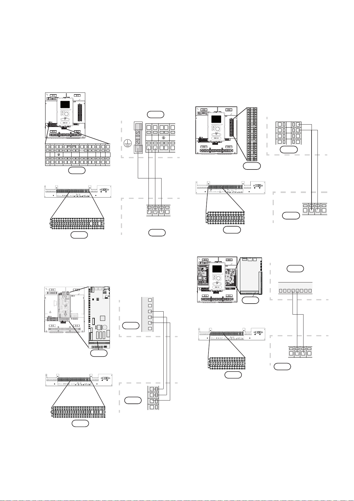
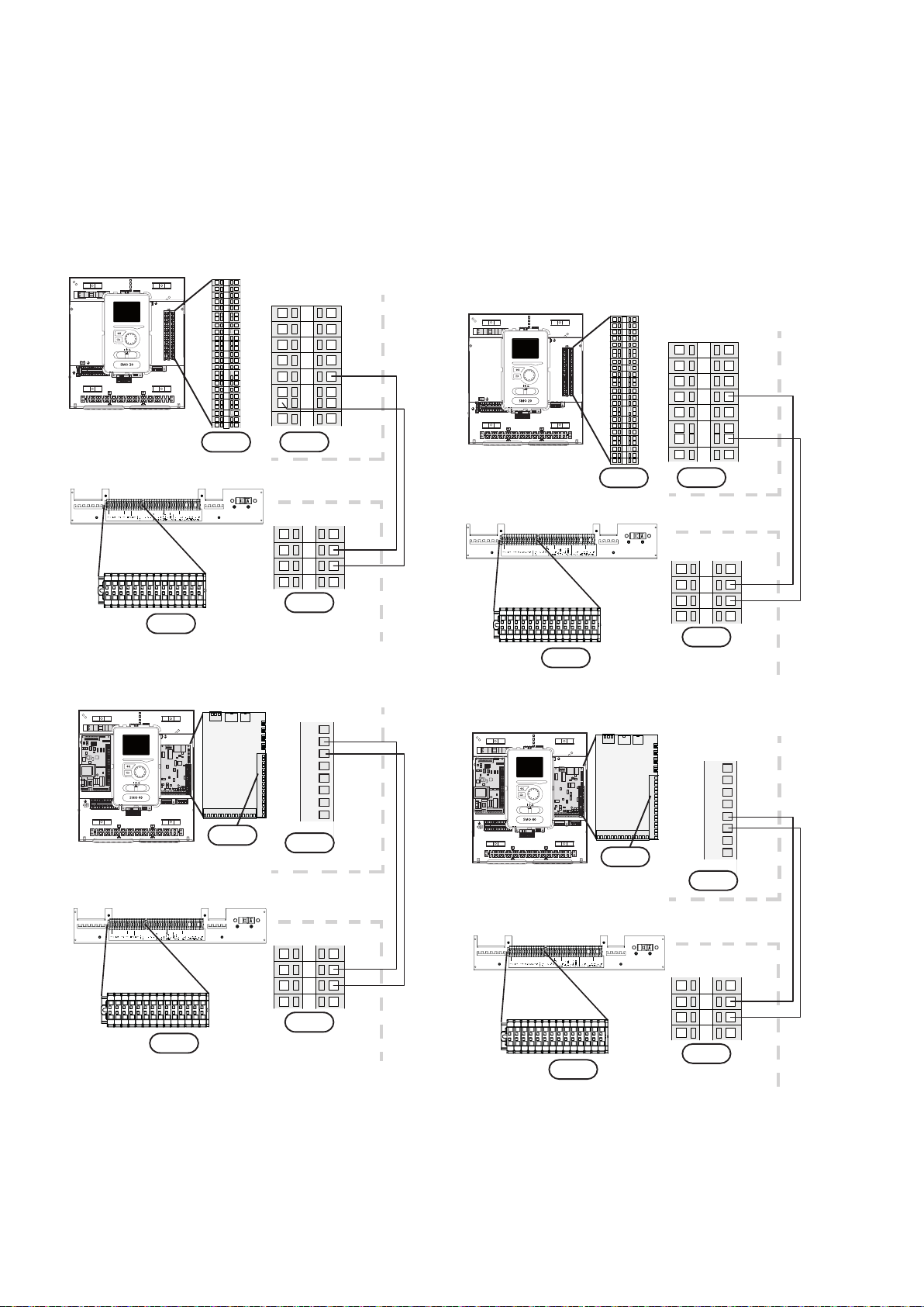
ConnectionsbetweenHK200MandSMO20/40
SMO 20/40 must be connected via the cut-off switch
with minimum contact-point gap of 3 mm. Minimum
cable cross-section is to be adjusted to the amperage
of fuses applied.
Connect the circulation pump (GP12) to clamps X4:5
(PE), X4:6 (N) and X4:7 (230 V) at the top board
(AA2), according to the drawing.
Power supply connection
Connecting the circulation pump
1NL
X1
LEK
L N 1 1 0 2 3 4PE
21 20 19 18 17 1615 14 13 12 11 10 9 8 7 6 5 4 3 2 1
X1
1 1NL 0 EP 2 3 4
X2
L
HK 200M
HK 200M
SMO 20
SMO 40
SMO 20/40
N PE
SMO
X2
PE
L
N
HK 200M
SMO20
SMO 40
987654
AA2-X4
X2
GP12
LEK
L N 1 1 0 2 3 4PE
AA2-X4
SMO20/40
L
N
PE
HK 200M
X2
Chapter 5 | Electrical connections
SMO 20
SMO 40
Connect the control signal (GP12) for SMO 20 to
clamps X2:1 (PWM) and X2:2 (GND), while for SMO
40 to clamps X4:8 and X4:7, according to the draw-
ing.
2
1
4
3
SMO
Externt
HK 200M
SMO20
SMO20
X2
PWM
GND
LEK
L N 1 1 0 2 3 4PE
21 20 19 18 17 1615 14 1312 11 10 9 8 7 6 5 4 3 2 1
X2
5
6
7
2
1
8
9
13
12
4
3
11
10
19
20
21
14
18
16
17
15
X1
PWM
GP12
GND
HK 200M
X1
Externt
HK 200M
SMO40
PWM
GND
X1
PWM
GND
5 467891011
AA3-X4
SMO40
L N 1 1 0 2 3 4PE
1 2 3 4
LEK AA3-X4
GP12
HK 200M
X1
19HK 200M Chapter 5 | Electrical connections
SMO 20
SMO 20
SMO 40
SMO 40
Temperature sensor, hot water loading DHW temperature sensor
Temperature sensor, hot water loading (BT6) is locat-
ed at the bottom part on the DHW heater.
The sensor must be connected - for SMO 20 to clamps
X2:5 and X2:6, while for SMO 40 to clamps X6:7 and
X6:8. Use a two-wire cable with the cross-section of
at least 0.5 mm².
Temperature sensor in the top part of the DHW heater
(BT7) indicates water temperature at the top part of
the tank.
The sensor must be connected - for SMO 20 to clamps
X2:4 and X2:6, while for SMO 40 to clamps X6:15
and X6:16.Use a two-wire cable with the cross-sec-
tion of at least 0.5 mm².
5
6
7
2
1
4
3
HK 200M
SMO20
X2
X1
BT6
LEK
L N 1 1 0 2 3 4PE
21 20 19 18 17 1615 14 13 12 11 10 9 8 7 6 5 4 3 2 1
X2
5
6
7
2
1
8
9
13
12
4
3
11
10
19
20
21
14
18
16
17
15
SMO20
HK 200M
X1
HK 200M
SMO40
X1
BT6
6
7
8
9
10
11
12
13
AA3-X6
SMO40
L N 1 1 0 2 3 4PE
1 2 3 4
LEK AA3-X6
HK 200M
X1
5
6
7
2
1
4
3
HK 200M
SMO20
X2
X1
BT7
LEK
L N 1 1 0 2 3 4PE
21 20 19 18 17 1615 14 13 12 11 10 9 8 7 6 5 4 3 2 1
X2
5
6
7
2
1
8
9
13
12
4
3
11
10
19
20
21
14
18
16
17
15
SMO20
HK 200M
X1
HK 200M
SMO40
X1
BT7
11
12
13
14
15
16
17
18
AA3-X6
SMO40
L N 1 1 0 2 3 4PE
1 2 3 4
LEK AA3-X6
HK 200M
X1

20 HK 200MChapter 5 | Electrical connections
Temperature sensor, on
supply pipeline
Temperature sensor on cooling supply (BT25) must
be connected for SMO 20 to clamps X2:8 and
X2:10, while for SMO 40 to clamps X6:5, X6:6. Use
a two-wire cable with the cross-section of at least 0.5
mm².
9
10
11
6
8
7
HK 200M
SMO20
X2
X1
LEK
L N 1 1 0 2 3 4PE
21 20 19 18 17 16 15 14 13 12 11 10 9 8 7 6 5 4 3 2 1
X2
5
6
7
2
1
8
9
13
12
4
3
11
10
19
20
21
14
18
16
17
15
BT25
HK 200M
X1
HK 200M
SMO40
X1
BT25
4
5
6
7
8
9
10
11
AA3-X6
SMO40
L N 1 1 0 2 3 4PE
1 2 3 4
LEK AA3-X6
HK 200M
X1
SMO 20
SMO 40
Temperature sensor on the supply pipeline at
the heating module upstream the isolation valve
(QN10)
Temperature sensor on the pipeline downstream the
heating module (BT63) must be connected in SMO
20 to clamps X2:9 and X2:10, while in SMO 40 to
AUX clamps, e.g.: X6:13 and X6:14, and then turn on
sensor power supply - see SMO40 installation man-
ual. Use a two-wire cable with the cross-section of at
least 0.5 mm².
9
10
11
6
8
7
HK 200M
SMO20
SMO20
X2
X1
BT63
LEK
L N 1 1 0 2 3 4PE
21 20 19 18 17 16 15 14 13 12 11 10 9 8 7 6 5 4 3 2 1
X2
5
6
7
2
1
8
9
13
12
4
3
11
10
19
20
21
14
18
16
17
15
SMO20
HK 200M
X1
HK 200M
SMO40
X1
BT63
L N 1 1 0 2 3 4PE
1 2 3 4
LEK AA3-X6
SMO40
7
8
9
10
11
12
13
14
AUX3
AUX2
AUX1
AA3-X6
HK 200M
X1
SMO 20
SMO 40
Table of contents
Other NIBE-BIAWAR Heat Pump manuals

Popular Heat Pump manuals by other brands

Hillphoenix
Hillphoenix CO2One manual

alphainnoTec
alphainnoTec LWC Series operating manual

Glowworm
Glowworm Envirosorb 5 installation manual

Grandaire
Grandaire R4H3 Series installation instructions

Sunsystem
Sunsystem TDA Series Installation and operation manual

OCEANAIRE
OCEANAIRE 2OACH1211 Engineering, installation and service manual


Daikin Altherma
Daikin Altherma EHVH04SU18CB6W installation manual

Trane
Trane Axiom GEHB Installation operation & maintenance

Trane
Trane 4TTR7 Series Installer's guide

HTW
HTW RSJ Series Owners and installation manual

Lennox
Lennox Magic-Pak PWC182 Installation and maintenance instructions

Toshiba
Toshiba HWT-601XWHM3W-ETR Service manual