NIBE-BIAWAR HK 200S User manual

16.10.2018
25959
Installation and operating manual
Indoor unit
Cooperating with air
heat pumps
HK 200S
HK 200S-6
HK 200S-6

HK 200S
HK 200S-6
Navigation
Room temperature setting
Detailed description of button functions to be found in
section Display.
Moving about the menu and inputting various settings
has been specied in the Menu Selection section.
The room temperature setting mode is selected by
pressing the OK button twice from the start mode lev-
el in the main menu. More information to be found in
section Room temperature setting.
SMO 20
SMO 40
In order to temporarily increase hot water volume rst
turn the control knob to mark menu 2 (icon presenting
water drop) and press the OK button twice. More
information to be found in section Setting hot water
output
If there are any distortions to the heat comfort, before
contacting the installation technician, you can per-
form some activities yourself.Appropriate instructions
can be found in section Canceling the settings.
Increase hot water volume
If the heat comfort is distorted
Ok button
(conrm/select)
Back Button (back/
cancel/exit)
Regulation knob
(move/increase/decrease)
Quick Guide
SMO 20
SMO 40

3List of contents |HK 200S
HK 200S-6
List of contents
1 Important information _______ 4
Information regarding safety ____________4
2 Supply and operation________ 6
Transport___________________________6
Assembly___________________________6
Included items_______________________6
Removal of the covers_________________6
3 Indoor module structure _____ 7
HK 200S / HK 200S-6 _________________7
4 Pipe connections ___________ 9
General pipe connections ______________9
Dimensions and pipe connections_______12
Connection options __________________13
5 Electrical connections ______ 19
General information__________________19
Connections________________________20
Settings ___________________________28
6 Start-up and regulation _____ 29
Preparations _______________________29
Filling and venting ___________________29
Start-up and acceptance______________30
7 Control __________________ 31
Display____________________________31
System menu_______________________31
8 Service___________________ 32
Maintenance service _________________32
9 Distorted heat comfort______ 33
10 Accessories _____________ 33
11 Technical data____________ 34
Dimensions and layout of connections ___34
Technical data ______________________35
Performance _______________________36
Energy labelling_____________________37
Data for energy efciency of the package _37
Diagram of electrical connections, 3x400V_41

4HK 200S
HK 200S-6
1 Important information
Information regarding
safety Serial number
Symbols
Marking
HK 200S / HK 200S-6 features the CE mark and wa-
ter protection IP21.
The CE mark con rms that NIBE-BIAWAR has taken
care for product conformity with applicable regula-
tions of relevant EU Directives. The CE is required
for most products sold in the EU, regardless of their
place of manufacture.
IP21 means that items with the diameter greater or
equal to 12.5 mm cannot access inside causing dam-
age, and that the product has been secured against
vertically falling water drops.
The device can be operated by childred aged over 8
and persons with physical, sensoric, or mental dis-
abilities, and without any experience or knowledge
about its operation, if supervised or trained in safe
operation, and if they understand the risks related
to its operation. The device must not serve as a toy
for children. Activities related to cleaning and basic
maintenance must not be performed by unsupervised
children.
Rights to implement design changes are reserved.
©NIBE-BIAWAR 2018
This manual contains installation and maintenance proce-
dures for specialists.
The serial number is located at the top of HK 200S /
HK 200S-6
IMPORTANT
This symbol informs about the risk to the device or a
person
CAUTION
This symbol points to important information to be not-
ed when operating the device.
ADVICE
This symbol shall mean tips to make product opera-
tion easier.
CAUTION
When contacting the installation technician, always
provide the product serial number (14 digits).
Serial
number
Waste disposal
Information for particular countries
Disposal of the packaging shall be the
responsibility of the installation techni-
cian installing the product, or a special
waste management facility.
Incorrect disposal of the product by the user is sub-
ject to administrative penalties under applicable regu-
lations.
Installation manual
This installation manual must be submitted to the Cli-
ent.
Do not dispose of decommissioned prod-
ucts together with regular household
wastes. Hand them over to a specialist
facility.
dealing with waste disposal or salesperson offering
such services.
Chapter 1 | Important information

5HK 200S
HK 200S-6
Description Notes Signature Date
Heating medium
Installation rinsing
Installation venting
Diaphragm expansion vessel
Particulate lter
Safety valve
Cut-off valves
Pressure in the heating system
Connection according to the drawing
Hot water
Cut-off valves
Mixing valve
Safety valve
Power supply
Communication connection
Circuit fuses
Fuses, internal module
Building fuses
Temperature sensor outdoor
Room sensor
Energy meter
Emergency switch
Switch differential
Thermostat emergency mode setting
Miscellaneous
Connected to
Installation acceptance
The heating system must be accepted before start-up. Acceptance must be done by a person with appropriate
qualications. Complete the card in the operating manual by entering the installation data.
CHECKLIST
Chapter 1 | Important information

6HK 200S
HK 200S-6
2 Supply and operation
Transport
Assembly
HK 200S / HK 200S-6 heat pump must be transported
and stored vertically in a dry place. HK 200S / HK 200S-6
can be, however, carefully placed on the rear side of the
casing when carrying the device into the building.
Leave 800 mm free space at the front of the heat pump.
All maintenance works on HK 200S / HK 200S-6 can be
done from the front.
Side covers are installed for permanent, therefore,
they cannot be disassembled.
• HK 200S / HK 200S-6 must be set on a solid wa-
terproof base that would keep the weight of the
indoor unit. The regulated legs of the heat pump
allow for levelling and stable setting of the device.
• Because HK 200S / HK 200S-6 is equipped with
condensate drain, indoor unit installation site
must be furnished with a oor drain with a dis-
charge to the sewer system. 1. Remove screws at the bottom edge of the front
cover.
2. Tilt the cover at the bottom edge and lift.
Installation site
IMPORTANT
Leave 10 – 25 mm free space between the indoor
module and the back wall for cables and piping.
800 mm
Removal of the covers
1
2
Chapter 2 | Supply and operation
20-40 mm
Included items
Safety valve
with pressure gauge
Wrench size 13

7HK 200S
HK 200S-6
3 Indoor module structure
HK 200S/ HK 200S-6
Chapter 3 | Indoor module structure
XL10
XL11
QN12
QN10
GP12
EP2
CM1
EB1
XL4 XL13 XL14 XL3 XL2
XL1
BP4
EB15
BT15
BT71
BT6
EB2
BT64
BT63
BT7
BT12
BT3
BT25

8HK 200S
HK 200S-6
K1-K3
T1
F1
F2
AA23
AA8
X3
F3
LEGEND
Chapter 3 | Indoor module structure
X1 X2
Pipe connections
XL1 Connection, heating medium, supply
XL2 Connection, heating medium, return
XL3 Connection, cold water
XL4 Connection, hot water
XL10 Connection, cooling
XL11 Connection, safety group,
manometer
XL13 Connection, liquid cooling medium
XL14 Connection, gas cooling medium
HVAC elements
CM1 Diaphragm expansion vessel, closed
QN10 Isolation valve, domestic hot water / cen-
tral heating
QN12 Isolation valve, cooling/heating
GP12 Circulation pump
EP2 Heat exchanger
Sensors
BP4 Pressure sensor, high pressure
BT3 Temperature sensor, heating medium re-
turn
BT6 Temperature sensor, hot water loading
BT7 Temperature sensor, top of the hot water
heater
BT12 Temperature sensor, condenser outlet
BT15 Temperature sensor, liquid
BT25 Temperature sensor, heating medium
supply
BT63 Temperature sensor, heating medium
supply downstream the submersible heat-
er
BT64 Temperature sensor, cooling medium
supply
BT71 Temperature sensor, heating medium re-
turn
Electrical elements
X1 Coupling
X2 Coupling
X3 Coupling
K1-K3 Submersible heater switch
T1 Thermostat - emergency mode
AA23 Communication card
AA8 Titanium anode card
F3 Temperature limiter
F1 Circuit breaker
(to external module)
F2 Circuit breaker
(to internal module)
EB1 Submersible heater
Other
EB15 HK 200S / HK 200S-6
PF3 Serial number
EB2 Domestic hot water tank
EMERGENCY
SMO SMO AMS 10-6

9HK 200S
HK 200S-6
4 Pipe connections
General pipe connections
The piping installation must be executed according to
the applicable standards and directives.
HK 200S / HK 200S-6 indoor unit NIBE SPLIT out-
door air heat pump, and controller NIBE SMO form a
complete heating system.
The system can cooperate with a low- and medium-
temperature heating system. Recommended temper-
ature of the heating medium at minimum designed
outdoor temperature DOT must not exceed 55°C on
supply, and 45 °C on return circuit from the heating
system, whereas HK 200S / HK 200S-6 can achieve
even 65 °C when using a ow-through heating mod-
ule or another peak heat source.
Excess medium owing out of the safety valve must
be discharged via a pipe to a oor drain. The over-
ow pipe must be slanted at the entire length from the
safety valve, and must be secured against freezing.
In order to achieve maximum system efciency, we
recommend the installation of HK 200S / HK 200S-6
as close to the heat pump as possible.
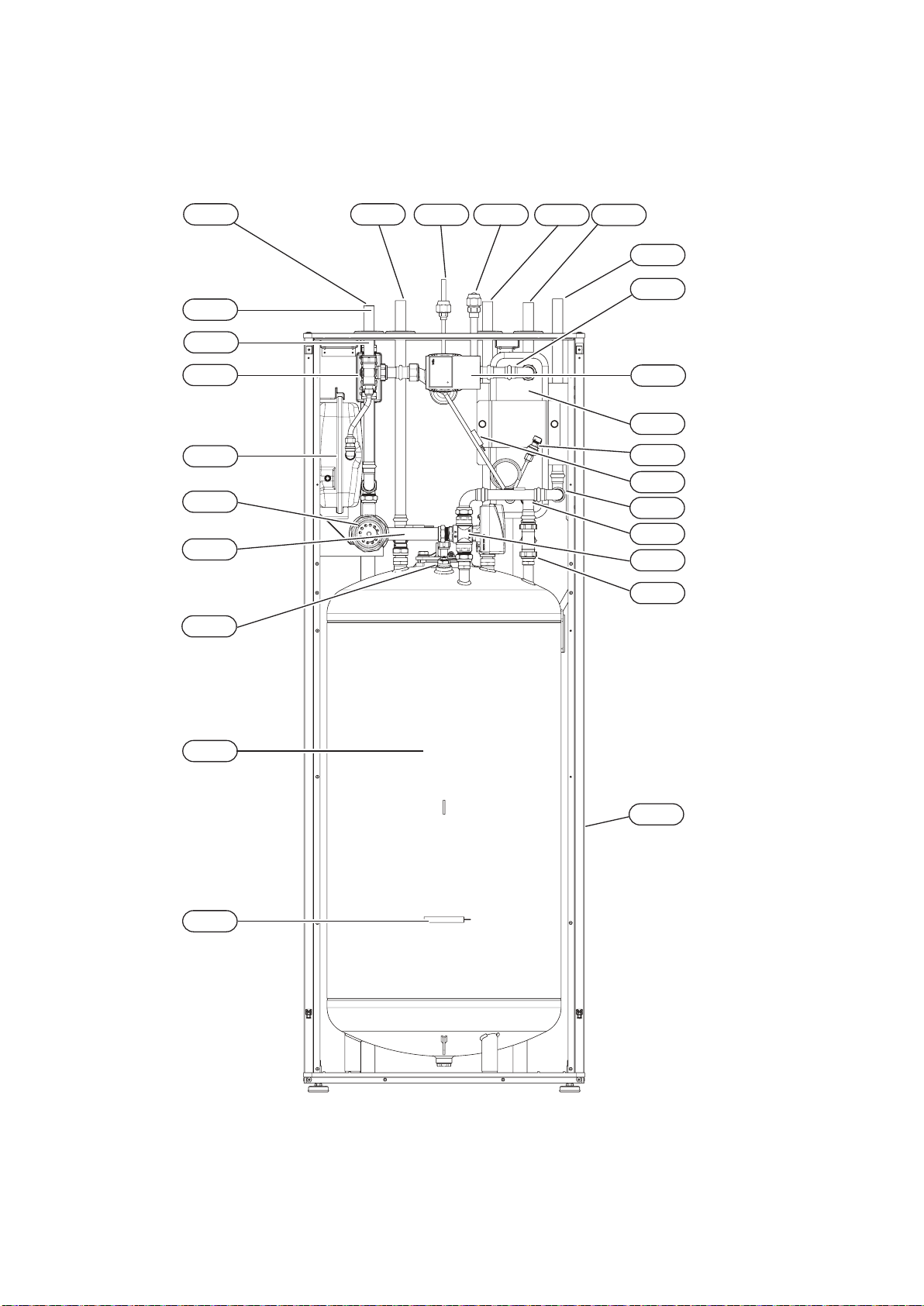
The HK 200S / HK 200S-6 module is not equipped
with cut-off valves, which must be installed outside
the indoor module to make future maintenance eas-
ier. The HK 200S / HK 200S-6 module can be con-
nected to the central heating, cooling, and domestic
hot water installation. Install the supplied safety valve
and the manometer.
HK 200S / HK 200S-6 is equipped with a diaphragm
expansion vessel for a heating circuit of 10 I. Initial
pressure of the expansion vessel must be set appro-
priately to the maximum height (H) between the ves-
sel and the highest heater, see the drawing. The ini-
tial pressure of 0.5 bar (5 mvp) shall mean maximum
permissible height difference of 5 m.
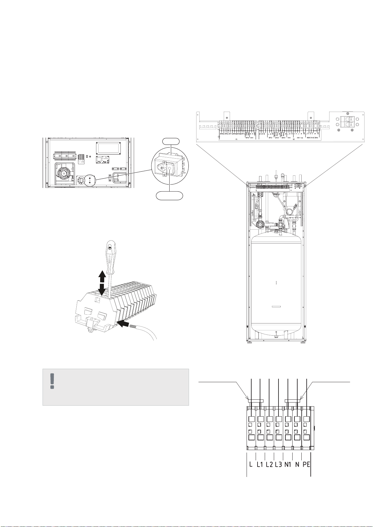
If the standard initial pressure in the diaphragm ex-
pansion vessel is too low, it can be raised by lling the
vessel through the valve installed.
Any change to the initial pressure affects the dia-
phragm expansion vessel’s capacity to support the
increase in water volume.
IMPORTANT
All places in the heating system located high must be
equipped with vents.
IMPORTANT
Pipelines must be rinsed before connecting the indoor
module so that possible dirt does not damage its ele-
ments.
IMPORTANT
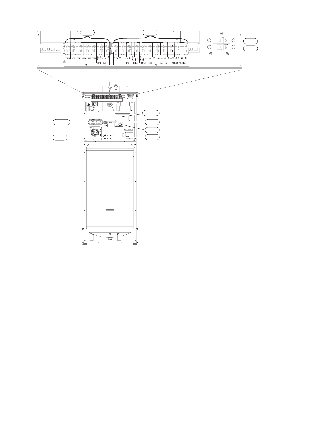
As long as heating circuits in the system have not been
lled with the heating medium, do not set the switch
(SF1) in the SMO module in position “I” or “ ”. The
compressor in the heat pump and the ow-through
heating module can be damaged.
Capacities of the indoor unit and the
heating system
System requirements
The inner capacity of HK 200S / HK 200S-6 for the
purposes of calculating the diaphragm expansion
vessel in the domestic hot water installation totals
180 l. The capacity of the diaphragm expansion ves-
sel must constitute at least 5% total capacity.
Minimum required conguration:
In order to assure correct operation, the capacity of
the heating system must meet the requirements for
the installation. If this condition has not been met, in-
stall an additional buffer tank.
CAUTION
In this case a diaphragm expansion vessel of the
DHW installation must have the capacity of 10l. The
diaphragm expansion vessel at the domestic hot water
installation is not required. It is, however, required to
install a safety valve with opening pressure of 6 bar.
IMPORTANT
All connections require free ow, hence a discharge
valve must be installed.
Chapter 4 | Pipe connections

10 HK 200S
HK 200S-6
Symbol Meaning
Vent
Cut-off valve
Water tap
Non-return valve
Balancing valve
Three-way valve
Safety valve
Thermometer
Temperature sensor
Diaphragm expansion
vessel
P
P
HK 200S-6
HK 200 M
P
XL10
XL1
XL2
The HK 200S / HK 200S-6 indoor unit is equipped with a coil
water heater, diaphragm expansion vessel , safety group,
electric heater, isolation valves, plate heat exchanger, meter-
ing instruments, and an electronic circulation pump. Together
with the outdoor unit of air heat pump NIBE SPLIT and NIBE
SMO module, it forms a complete heating system.
The AMS 10 outdoor unit provides heat for heating the do-
mestic hot water and supplying the heating system while
using free energy in the outdoor air, efciently operating
within the range of low temperatures up to -20°C.
The connection of the outdoor unit and indoor unit HK
200S / HK 200S-6 with a system of pipes lled with
a cooling medium secures the connection against
freezing in the event of any power outages. The con-
trol of system operation is the function of SMO 20 or
SMO 40 module.
Installation diagram
Chapter 4 | Pipe connections
T
P
T
P
T
P
T
P
T
P
T
P
T
P
T
P
T
P
T
P
Symbol Meaning
Manometer
Circulation pump
Particulate lter
T
P
Compressor
T
P
Heat exchanger
Cooling
Central heating system
Domestic hot water
Relief valve
T
P
T
P
T
P
T
P
T
P
HK 200S

11HK 200S
HK 200S-6
Indoor HK 200S / HK 200S-6 module
• It is recommended that the HK 200S / HK 200S-6
module should be installed in a room with a oor
drain, at best in a utility room or a boiler house.
• The oor must be solid, concrete at best.
• The HK 200S / HK 200S-6 module must be set
with its back to the outer wall, at best in a room
where noise is not a problem. If possible, do not
place the device near a wall of a bedroom or an-
other room where noise might be a problem.
• The device can be leveled using regulated legs.
• Pipes must be led in such a way that they are not
adjacent to the bedroom or living room.
• Remember to leave about 800 mm free space at
the front and 220 mm over the device to provide
for future maintenance.
1. Connect HK 200S / HK 200S-6 module to the
heating system, cold, and hot water pipelines.
2. Install the cooling medium pipes.
3. Connect the outdoor temperature sensor, and
cables between HK 200S / HK 200S-6 and SMO
20/40.
4. Connect power supply to module HK 200S / HK
200S-6.
5. Proceed according to start-up instructions in
chapter Start-up and regulation.
Recommended order of assembly
Chapter 4 | Pipe connections

12 HK 200S
HK 200S-6
Chapter 4 | Pipe connections
Dimensions and pipe connections
XL11
XL10
XL4
XL14XL13 XL4
XL5
XL5
XL3
XL3
XL2
XL2
XL1
XL1
XL14
XL13
Pipe connections
XL1 Connection,HeatingmediumsupplyØ22mm
XL2 Connection, Heating medium return Ø22 mm
XL3 Connection, cold water Ø22 mm
XL4 Connection, hot water Ø22 mm
XL5 Connection, circulation Ø15 mm
XL10 Connection, cooling Ø22 mm
XL11 Connection, safety group
Ø22 mm, manometer
XL13 Liquid cooling medium
Connection ¼” (HK 200S-6)
Connection ⅜” (HK 200S)
XL14 Gas cooling medium
Connection ½” (HK 200S-6)
Connection ⅝” (HK 200S)
PF3
20-40
1589 115
600.5
610.5
300
156
93.5 92.5 87 63 55
65
15544
152
legs adjustment
XL11
XL10
Other information
PF3 Serial number plate

13HK 200S
HK 200S-6
Connection options
Compatible heat pumps
air/water by NIBE with unit
HK 200S / HK 200S-6
Connecting the heating system
Indoor HK 200S / HK 200S-6 units can cooperate
with external units of Split type.
Compatible heat pumps NIBE SPLIT include:
An external heat source, e.g. a gas or oil boiler, can
be connected to (XL1) (input) and (XL2) (output) at
HK 200S / HK 200S-6.
The HK 200S / HK 200S-6 module is equipped with a
condensate hose in the heat exchanger section. The
hose drains all condensate away from the device to
minimize the risk of damage. If necessary, the hose
can be extended.
Refrigerant pipes must be installed between the ex-
ternal module AMS 10 and HK 200S / HK 200S-6.
The installation must be executed according to the
applicable standards and directives.
Condensate hose
Limitations
• Maximum pipe length, AMS 10-6, AMS 10-8,
AMS 10-12 (L): 30 m.
• Maximum height difference (H): ±7 m.
Pipe connections of the heating system are to be
made at the top.
• All the required protections and cut-off valves
must be installed as close to the HK 200S / HK
200S-6 module as possible.
• Where necessary, install the vents.
• Safety valve with a nanometer at the central heat-
ing circuit and the safety valve at the hot water
system must be installed on relevant conductors
XL 11 and XL 4. In order to prevent air sockets,
the overow pipe must be slanted at the entire
length from the safety valve, and must be se-
cured against freezing.
• When connecting to the installation where all
heaters have been equipped with thermostat
valves, install a discharge valve or remove sev-
eral thermostats to assure appropriate ow.
Symbol Application
AMS 10-6 HK 200S-6
AMS 10-8 HK 200S
AMS 10-10
IMPORTANT
The term “heating system”, as used in this installation
and operation manual, shall mean the heating or cool-
ing system supplied with a hot or cold medium from
the HK 200S / HK 200S-6 module for heating or cool-
ing purposes.
Connecting an external heat source
Condensate elimination
Connecting refrigerant pipes
(not supplied)
L
H
L
H
HK 200S-6
HK 200S-6
AMS 10
AMS 10
More information about NIBE SPLIT to be found at
www.nibe.eu and in relevant installation manuals for
accessories used.
ChapterAccessories can serve to check the list of ac-
cessories to be used with HK 200S / HK 200S-6.
Chapter 4 | Pipe connections
CAUTION
Suitable safety valve must be installed directly on the
cold water supply line to the hot water tank. Safety
valve will protect against excessive increase of pres-
sure.
IMPORTANT
Installation of any extensions (e.g. reducers, lters
etc.) and shut-off valves between the XL4 connection
and the safety valve is not allowed. It is only permit-
ted mounting three-way adapter with drain valve that
allows to empty the tank and three-way adapter with
expansion vessel.

14 HK 200S
HK 200S-6
Pipe dimensions and materials
HK 200S Gas pipe Liquid pipe
Pipereplacement Ø15,88 mm (5/8”) Ø9,52 mm (3/8”)
Connection Connection– (5/8”) Connection–(3/8”)
Material Quality of copper SS-EN 12735-1 or
C1220T, JIS H3300
Minimum ma-
terial thickness 1.0 mm 0.8 mm
HK 200S-6 Gas pipe Liquid pipe
Pipereplacement Ø12.7 mm (1/2”) Ø6,35 mm (1/4”)
Connection Connection– (1/2") Connection–(1/4”)
Material Quality of copper SS-EN 12735-1 or
C1220T, JIS H3300
Minimum ma-
terial thickness 1.0 mm 0.8 mm
Pipe connection
• Execute the pipe installation with the mainte-
nance valves (QM35, QM36) closed.
AMS 10-6 / AMS 10-8
• Remove the side panel on AMS 10 during the in-
stallation to make access easier.
Socket connections
Extension:
Shift:
LEK
LEK
Przód
Elementy do wybicia
IMPORTANT
When soldering, apply the shielding gas.
Chapter 4 | Pipe connections
Outer
diameter ,
copper pipe
(mm)
B, using the
R410A tool
(mm)
B, using a con-
ventional tool
(mm)
Ø 9,52
0,0~0,5 0,7~1,3
Ø 15,88
Ø 6,35 1,0~1,5
Ø 12,7
External
diameter, cop-
per pipe (mm)
Torque
(Nm)
Tighten-
ing angle
(°)
Recom-
mended tool
length
(mm)
Ø6,35 14~18 45~60 100
Ø 9,52 34~42 30~45 200
Ø12,7 49~61 30~45 250
Ø 15,88 68~82 15~20 300
AMS 10-12
• Remove the “to be removed” part from the exter-
nal panel at the AMS 10 mode where pipes are
to be led. The drawing below presents exemplary
pipe outlets.
• Make sure that no water or dirt can permeate to
the pipes.
A
B
Vacuum
pump
Serviceventil, gas
Mätuttag
Manometer
Serviceventil, vätska
Zawór serwisowy,
ciecz
Zawór serwisowy,
gaz
Wyjście pomiarowe
Manometr
Pompa
próżniowa
A
B
Vacuum
pump
Serviceventil, gas
Mätuttag
Manometer
Serviceventil, vätska
Zawór serwisowy,
ciecz
Zawór serwisowy,
gaz
Wyjście pomiarowe
Manometr
Pompa
próżniowa
A
B
Vacuum
pump
Serviceventil, gas
Mätuttag
Manometer
Serviceventil, vätska
Zawór serwisowy,
ciecz
Zawór serwisowy,
gaz
Wyjście pomiarowe
Manometr
Pompa
próżniowa
External diameter, copper pipe A (mm)
Ø 6,35 9,1
Ø 9,52 13,2
Ø 12,7 16,6
Ø 15,88 19,7
HK 200S
HK 200S-6
• Bend pipes with maximum bending radius (at
least R100~R150). Do not bend pipes many
times. Use a bending machine.
• Connect the socket connection and tighten with
appropriate torque. Apply the appropriate tight-
ening angle if the torque wrench is not available.

15HK 200S
HK 200S-6
Pressure test and leakage test
Vacuum pump
Insulation of cooling medium pipes
Filling the system with a cooling medium
A
B
Vacuum
pump
Serviceventil, gas
Mätuttag
Manometer
Serviceventil, vätska
Zawór serwisowy,
ciecz
Zawór serwisowy,
gaz
Wyjście pomiarowe
Manometr
Pompa
próżniowa
Both HK 200S-6 / HK 200S and AMS 10 are factory-
tested for pressure and leakage, but pipe connec-
tions between the devices must be checked when the
installation has been completed. When executing pipe connections, pressure tests,
leakage tests and vacuum tests, maintenance
valves can be open to ll the pipes and HK 200S-6 /
HK 200S with a refrigerant medium.
Connections:
Principle:
• Cooling medium (both gas and liquid) pipes must
be insulated to provide thermal insulation and
prevent condensation.
• Apply insulation that can sustain at least 120°C.
Insufciently insulated pipes can cause problems
with insulation and unnecessary wear of the ca-
bles.
Use a vacuum pump to remove all air. Turn on ex-
traction for at least one hour. Final pressure, after
emptying, must total 1 mbar (100 Pa, 0.75 Tr or 750
microns) of absolute pressure. If the system is still
moist or is leaking, negative pressure will grow after
the end of emptying.
IMPORTANT
Pipe connections between devices must undergo a
pressure test and leakage test after completing the in-
stallation process, according to applicable regulations.
Use nitrogen only for system compression and rinsing.
ADVICE
In order to achieve a better nal effect and to acceler-
ate emptying, follow the following sections.
• Pipelines should have the largest diameter pos-
sible, and be as short as possible.
• Empty the system to 4 mbar and ll it with dry ni-
trogen to atmospheric pressure to end emptying.
AMS 10 is supplied together with a refrigerant me-
dium for cooling medium of max. length of 15 m.
If the length of the cooling medium pipes exceeds 15
m, supplement the cooling medium in the volume of
0.06 kg/m.
IMPORTANT
In the case of systems with cooling medium pipes with
the length of up to 15 m, the supplied volume of the
cooling medium is sufcient.
Wires for connecting indoor
and outdoor units Exterior tape
Gas piping
Insulation
Liquid piping
Okablowanie
Rura z cieczą
Taśma
Rura gazowa
Izolacja
Przyłącza:
Band (accessory) Pipe cover (accessory)
Zworka Zabezpieczenie rury
Wires for connecting indoor
and outdoor units Exterior tape
Gas piping
Insulation
Liquid piping
Okablowanie
Rura z cieczą
Taśma
Rura gazowa
Izolacja
Przyłącza:
Band (accessory) Pipe cover (accessory)
Zworka Zabezpieczenie rury
Chapter 4 | Pipe connections
Measurement output
Maintenance
valve - liquid
Maintenance
valve - gas
Manometer
Vacuum
pump
Cabling Tape
Gas pipe
Insulation
Pipe for liquid
Jumper Pipe protection

16 HK 200S
HK 200S-6
Connections
Mounting requirements
General information
NIBE SPLIT can be connected in many various ways.
More information on connections to be found at web-
site www.nibe.eu.
Chapter 4 | Pipe connections
AMS 10-6 AMS 10-8 AMS 10-12
Max pressure, climate system 0.25 MPa (2.5 Bar)
Highest recommended supply/return temperature at dimensioned out-
door temperature 55/45 °C
Max temperature in HK 200S / HK 200S-6 +65 °C
Max ow line temperature with compressor +58 °C
Min supply temperature cooling +7 °C
Max supply temp. cooling +25 °C
Min volume, climate system during heating, cooling* 50 l 80 l
Min volume, climate system during under oor cooling* 80 l 100 l
Max ow, climate system 0.38 l/s 0.57 l/s
Min ow, climate system, 100% circulation pump speed (defrosting
ow) 0.19 l/s 0.29 l/s
Min ow, heating system 0.12 l/s 0.15 l/s
Min ow, cooling system 0.16 l/s 0.20 l/s
* Regards circulating volume
External circulation pump must be used when the pressure drop in the system is greater than the available external pressure.
In such cases, a bypass line with non-return valve must be installed.
Overow valve must be used if min. system ow cannot be guaranteed.

17HK 200S
HK 200S-6
Connection to the heat pump
Connection when operating without a
heat pump
Connection of hot and cold water
All outdoor pipes must be thermally insulated with a
pipe lining with at least 20 mm thickness.
HK 200S-6 / HK 200S is not equipped with cut-off
valves, which must be installed outside the indoor
module to make future maintenance easier.
When connecting to the installation where all heaters/
oor heating pipes have been equipped with thermo-
stat valves, in order to assure appropriate ow, install
a discharge valve or a buffer in the parallel layout, or
remove several thermostats.
No change is required to the hydraulic connections
conguration for the internal unit to operate individu-
ally, without an external unit.
The installation of the mixing valve is necessary
if factory settings are changed in a way where the
temperature can exceed 60 °C. When changing the
factory settings, follow the national regulations in this
respect. The setting is entered in menu 5.1.1.
Heating system connection
P
P
P
P
P
P
P
P
The system can be extended by additional circuits ac-
cording to the capacity of the applied control module:
SMO 20 or SMO 40.
Additional accessories, capacity and connection
method have been specied in the manual for SMO
20 and SMO 40, in chapters Accessories and Electri-
cal connections.
Cooling system connection
P
P
Cooling is controlled by sensor BT64 and isolation
valve QN12. If cooling is needed, the isolation valve
changes the direction, and opens from the cooling
circuit side.
Optional connections
Chapter 4 | Pipe connections

18 HK 200S
HK 200S-6
XL5
XL5
DHW Circulation
HK 200S-6 / HK 200S have possibility to connect
DHW circulation. The circulation connection (XL5) is
located at the top of the tank.
To connect the circulation:
1. Remove the XL5 plug from the top of the housing.
520
120
Circulation pipe dimensions Elbow 15x15
2. Remove the front panel, then slide the control
panel down to access the hydraulic connections.
3. Remove the plug from the circulation pipe (XL5).
4. Install the elbow, facing the rear housing, on the
circulation pipe.
5. Connect the pipe to the elbow, with the dimen-
sions shown in the gure below, leading pipe in
the top of the housing, in place of the XL5 plug.
Mount the pipe insulation.
6. At the outlet of the circulation tube, install the cir-
culation pump and then connect its control to the
SMO (Chapter 5 Electrical connection).
7. Install the control panel and the front panel.
Chapter 4 | Pipe connections

19HK 200S
HK 200S-6
5 Electrical connections
General information
The entire electrical equipment, apart from outdoor
temperature sensors, room sensors, and current in-
tensity meters, has been connected according to fac-
tory settings.
• Disconnect the indoor module before performing
tests of electrical system insulation in the building.
• If the building is equipped with a differential
switch, HK 200S-6 / HK 200S must be equipped
with a separate switch.
• The diagram of indoor module connections can
be found in section „Diagram of electrical connec-
tions”.
• Do not lay communication and signal cables to
external contacts near high-voltage cables.
• Minimum cross-section of communication and
signal cables to external contacts must total 0.5
mm² with the length of up to 50 m, for example
EKKX or LiYY, or similar.
• When laying cables in HK 200S-6 / HK 200S, ap-
ply cable passes UB1 and UB2 (as marked in the
illustration). In UB1 and UB2, cables are input
through the entire indoor module from the back
wall towards the front wall.
IMPORTANT
As long as the heating circuits have not been lled with
the heating medium, and if the central heating system
has not been vented, the switch (SF1) in SMO cannot
be set in positions „I” or „ ”. Otherwise, the tempera-
ture limiter, thermostat and ow-through heater can be
damaged.
IMPORTANT
If the power supply cable is damaged, it can only be
replaced by authorised service, its technician, or other
qualied person, to avoid danger or damage.
IMPORTANT
The electrical installation and maintenance service
must be performed under the supervision of a qualied
power technician with relevant qualications. Before
starting any maintenance works, power supply must
be cut off using an automatic switch. The electrical in-
stallation and cabling must be executed according to
applicable regulations.
X1 Coupling
X2 Coupling
X3 Coupling
SF1 Controller switch
K1-K3 Submersible heater contact
T1 Thermostat, standby mode
F3 Temperature limiter
AA8 Titanium anode card
AA23 Communication card
F1 Circuit breaker (to external mod-
ule)
F2 Circuit breaker (to external mod-
ule)
UB1 Cable pass
UB2 Cable pass
F3-SF2 Reset
F2
F1
X1
T1
AA23
AA8
X3
F3
UB2 UB1
X2
K1-K3
LEGEND
Chapter 5 | Electrical connections

20 HK 200S
HK 200S-6
Temperature limiter (F3) is accessible behind the front
cover. Temperature limiter is reset by strong press-
ing of the button (F3-SF2) using a small screwdriver.
Press the button, max. 15 N (approx. 1.5 kg).
Resetting
Cable blockade
Use an appropriate tool to release/block cables in the
internal module clamps.
The power supply is to be connected to clamp (X2)
via the input at the back of the unit. The cable must be
dimensioned according to the applicable standards.
HK 200S-6 / HK 200S must be connected to the
power supply 400 V 3N AC 50Hz as speci ed on the
clamp (X2).
Connection
Connections
IMPORTANT
In order to prevent interferences, do not lay unshielded
communication and/or signal cables to external con-
tacts at the distances lower than 20 cm from high-
voltage cables.
Power supply connection
Temperature limiter
Temperature limiter (F3) cuts off the power supply of
the electrical heating module if the temperature in-
creases to the range of approximately 87 °C, and can
be reset manually.
F3
F3-SF2
EMERGENCY
SMO SMO AMS 10-6
Circuit breaker
The system for automatic regulation of the heating,
circulation pump, and their cabling at HK 200S / HK
200S-6 are secured internally with a circuit breaker
(F2). The external AMS 10 module and peripheries
are secured internally at HK 200S / HK 200S-6 with
a circuit breaker (F1).
Chapter 5 | Electrical connections
2
1
3
L1L L2 L3 N N PE
Remove the bridge
for double tariff
control
Remove the bridge
for double tariff
control
This manual suits for next models
1
Table of contents
Other NIBE-BIAWAR Heat Pump manuals
Popular Heat Pump manuals by other brands

Daikin
Daikin altherma EJHA04AAV3 Installer's reference guide

Technibel
Technibel MCE089ZAA operating instructions

Sinclair
Sinclair SMH-100IRB Control and operation manual

LG
LG ARNU18GBHA1 owner's manual

Daikin
Daikin Super Multi NX FLXS25BAVMB Service Manual Removal Procedure

Kingspan
Kingspan Aeromax Plus Homeowner's guide