Nibe PB 10 User manual

MOS GB 0951-2
PB 10
511891
INSTALLATION AND MAINTENANCE INSTRUCTIONS
NIBE PB 10
LEK


1NIBE PB 10
User guide
General __________________________________ 2
Safety ___________________________________________ 2
System diagram __________________________________ 3
Installation
General information for the installer _______ 4
Assembly ________________________________________ 4
Checks __________________________________________ 5
Control device ____________________________________ 5
Care and maintenance ____________________ 6
Cleaning/Ash management: ________________________ 6
Maintenance schedule _____________________________ 6
Commissioning and adjusting _____________ 7
Feeding pellets ___________________________________ 7
Normal start (for factory settings) ___________________ 7
Settings _________________________________________ 8
Adjusting control electronics ________________________ 9
Adjusting the burner ____________________________ 10
Trimming tips __________________________________ 11
Check points after installation _____________________ 11
Safety system against back burning ______ 12
Description of functions _________________ 13
Wiring diagram _________________________ 14
Electrical connection PB 10 to PELLUX 200 _ 15
Electrical connection PB10 ________________________ 15
Electrical connection PELLUX 200 __________________ 15
Troubleshooting _________________________ 18
Contents
Miscellaneous
Component locations ____________________ 19
List of components ______________________ 19
Dimensions _____________________________ 20
Technical specifications __________________ 21
Accessories _____________________________ 22
Draft limiter ____________________________________ 23
Pellet screw ____________________________________ 24

2NIBE PB 10
User guide
General
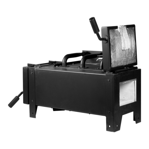
Pellet firing equipment NIBE PB 10 is intended for use with wood pellets after the
equipment has been docked to the boiler.
The pellet firing equipment PB 10 must not be lit with other combustible materials.
The pellet firing equipment PB 10 is installed in boiler rooms that meet Boverket’s
norms.
The rights to make any design modifications are reserved
This appliance is not intended for use by persons (including children) with reduced
physical, sensory or mental capabilities, or lack of experience and knowledge, un-
less they have been given supervision or instruction concerning use of the appli-
ance by a person responsible for their safety.
Safety
QThe installation must not be test run or operated until it has been connected to
the heating boiler and the smoke has free passage to the outside through the
flue or chimney. The boiler's flue gas damper must not be closed due to the risk
of ”ignition puffs” in the event of changing weather, therefore, the draft limiter
should be installed to ensure an even draft in the boiler and prevent back burn-
ing accidents.
The vacuum in the boiler hearth must be a minimum of 5 – 6 Pa (0.5 – 0.6 mm
VP)
QThe pellets must be stored in a dry and well-ventilated place.
The installation is designed to only be fired using wood pellets of Ø6 – Ø10 mm
in size.
QNote! Always use a mask when handling pellets.
QThe boiler room where the pellet equipment is installed must meet the current
edition of the Boverkets Building regulations, section: Fire prevention.
QWARNING! Electrical installations must only be carried out by an authorised
technician!
QThe pellet firing equipment must not modified, changed or redesigned without
written permission from the manufacturer.
QNon original spare parts, which do not correspond to the manufacturer's speci-
fications, can affect the safety of the pellet firing equipment and must therefore
not be installed without written permission from the manufacturer.
QThe pellet firing equipment must not be installed in combustible environments.
QCombustible material must not be stored close to the installation.
QWelding work must not be carried out on the installation before the power is
cut and the circuit board removed.
QDo not open any boiler doors during operation.
General

3NIBE PB 10
User guide
General
System diagram
M

4NIBE PB 10
Installation
General information for the installer
The boiler room where the equipment is to be installed
must be in accordance with the applicable fire safety regu-
lations.
Check points before installation:
QContact a chimney sweep to obtain approval that the
chimney can be used for pellet firing, and that the loca-
tion of the installation meets the applicable fire safety
regulations.
QContact the building and environmental office in your
district for basic building permits/notices about the
installation.
Assembly
The equipment must be positioned so that there is suf-
ficient space for cleaning and sweeping the burner, boiler
and flue.
The internal diameter of the chimney should be at least
125 mm. The recommended minimum chimney height for
this diameter is 6 m at 18 – 20 kW output.
Before installing the mounting frame (A) in the suitable
door opening on the boiler, the mounting holes for attach-
ment to the boiler must be drilled in the mounting frame,
screw the supplied counter sunk screws securely to the
mounting frame. If the swing arm is to be used, install it
on the mounting frame, then screw the mounting frame
securely to the boiler.
Install the burner in front of the boiler's water jacket. The
burner has an extended cover that directs the flame for-
ward. For installation in boilers without a spacer connector,
the extended cover can be cut to direct the flame upwards.
The distance from the bed of embers to the nearest boiler
surface must be 200 – 250 mm. This is so that the flame
has enough space and for optimum combustion.
Screw the burner to the cover frame using the supplied
knobs.
The connection between the burner and boiler must be
sealed, to prevent drafts and flue gas escaping.
The burner is set at the factory for 8 mm pellets of good
quality, approx. 12 kW supplied output at a screw angle of
45°.
The hose must be bent slightly and the hose connections
offset slightly from each other.
After the screws have been placed in the pellet reservoir or
store, refill with pellets and start the installation.
When the burner is installed on the boiler, an authorised
electrician must connect the electrical terminals to the
boiler's double thermostat according to the supplied wiring
diagram, (see wiring diagram) the power supply cable can
be separated. All connections to the burner must be made
via contacts in the chassis.
After the screws have been placed in the pellet reser-
voir or store with pellets and start the installation. See
"Commissioning and adjusting".
2
1
bar
3
04
T
G
20 100
4080
60
°C
0120
T
G
P
T
°C
°C
40
50
6070
90
80
10
20
30
60
70
80
40
50
45°
Alt. 1
Alt. 2
LEK
MR
MR
A

5NIBE PB 10
Installation
General information for the installer
Checks
Check for a risk of condensation in the flue by reading off
the flue gas temperature 1 m down from the chimney top.
If the temperature drops below 80 °C during the winter,
there is a risk of condensation. If the flue gas temperature
only falls below 80 °C by a few degrees, it may be enough
to install a counter-draft hatch on the flue, between the
boiler and chimney, in the boiler room. If the flue gas
temperature drops below 75 °C, an insert pipe should be
installed the entire length of the chimney.
Adjustment with the instrument should also be carried if
the pellet size or quality is changed.
There must not be any overpressure in the fireplace at any
time, i.e. during ignition, operation or extinguishing.
This can be checked by unscrewing the sight glass and
checking that smoke does not enter the boiler room.
Control device
Starting:
Start the installation by setting the boiler's main switch to
1 or on. Increase boiler's double thermostat to the desired
boiler temperature.
Stopping:
Lower the boiler thermostat.
Emergency stop:
Set the main switch of the boiler to 0 or off.
Make adjustments to the burner using a
flue gas analysis instrument for optimal
combustion.
Note!

6NIBE PB 10
Installation
Care and maintenance
Pellet firing equipment PB 10 has been developed for mini-
mal maintenance.
The majority of input required is to check the quality and
size of the pellets to be used.
Pellets must be stored in a dry and protected area.
Cleaning/Ash management:
When burning wooden pellets the residue is approx.
0.5 – 1 % ash.
The combustion area in combination with the fuel and the
consumption gives an idea of how often the burner should
be cleaned.
The ash must be stored in a closed container. Clean the
grate after burning about 400 litres of pellets or once a
week. The interval may be prolonged to every other week
depending on the pellet quality.
QLower the thermostat and allow the fan the run for 4
minutes (post combustion time).
QCut the power and allow the burner to cool down to
prevent the risk of burning injuries.
QRemove the knobs and pull/pry out the burner from the
boiler, remove any connection cables from the burner.
QRemove and clean the grate (105).
QRemove the ash from the burner and any from the
boiler.
QRemove any cinders from the ignition pod plate (107)
and clean the grate.
Note! The flat part of the grate must be slid in as far as
possible under the ignition pod plate.
Photocell
If necessary, clean the photocell (109) as follows:
QPull the photocell straight out.
QClean the photocell from soot, use a damp cloth if nec-
essary.
QCheck the position of the compression ring.
QReinstall the photocell in the groove.
Maintenance schedule
1. 2 – 4 times/month Remove ash and residue.
(Depending on pellet quality).
2. 2 – 4 times/month Clean the boiler's flues and
convection parts (the more often
this is done
the more economic use be-
comes).
3. 1 time/month Clean drop shaft and drop pipe.
4. 1 time/year Check the burner installation
using special tools (carried out
by the dealer or installer).
Before starting servicing and maintenance
work, power to the installation must be
cut by cutting the main power supply.
WARNING!
!
Welding work must not be carried out on
the installation before the power is cut
and the circuit board removed!
Note!
Care and maintenance
Ash can still contain glowing embers after
a long time. Therefore, always use a non-
inflammable container when emptying ash
and soot.
Note!
109
107105

7NIBE PB 10
Installation
Commissioning and adjusting
Feeding pellets
Start the pellet screw by inserting the plug in a wall socket.
It takes about 10-20 minutes before the pipe is filled to
the brim. This time applies for 1.5 meter screws and for an
angle of about 45°. Once the pellets have reached the brim
of the screw, allow it to run for about 2 minutes to fill the
pipe and for even feeding.
(Allow the pellets to drop into a bucket for easy return to
the store). Then transfer the plug to the burner's socket
and install the hose between the screw pipe and the pellet
burner.
Normal start (for factory settings)
1. Switch on the boiler's power switch and turn the boil-
er's thermostat to the desired temperature.
2. The thermostat requests heat.
3. The fan starts and vents the boiler and chimney for 15
seconds.
4. The fan slows to 1500 rpm, start dose supplies the
burner for 75 seconds.
5. The fan continues at 1500 rpm, until the photocell reg-
isters fire in the burner.
6. When the photocell has registered fire in the burner,
ignition is delayed for 15 seconds and the first batch of
pellets are fed in at 25 % of the set value on P2.
7. Overrun time is activated, the fan speeds up and the
burner supplies the desired amount of pellets at each
feed interval for 270 seconds.
8. After these 270 seconds the burner runs at 3.7 seconds
pellet feeding at each feed sequence, which is 15 sec-
onds. The burner runs in this mode until the thermostat
has reached its cut-off temperature.
9. At thermostat cut-off, the fan continues to run until
the photocell no longer registers fire. The extinguish-
ing time is activated in this mode, which corresponds to
150 seconds.
10.After extinguishing is complete, the burner can be re-
started.
The burner did not ignite at the first attempt:
1. The thermostat still requests heat.
2. The fans speeds up for 15 seconds.
3. The fans slows to 1500 rpm and new start dose of
37.5 seconds (50% of first set start phase) is supplied
to the burner. If the photocell registers light within 300
seconds, the process continues normally according to
step 6 (Normal start).
The burner did not ignite at the second attempt:
If no fire is registered at the second ignition attempt after
300 seconds, the burner extinguishes according to the set
value on P4. The burner gives an alarm via LD2 yellow LED
(lights continuously), the burner stops.
Before the burner is started again, the cause of the failed
ignition attempt must be established by trouble shooting.
The burner is reset by interrupting the current for at least 5
seconds, this allows the burner to be restarted.
The photocell loses light during firing:
If the photocell loses light for more than 30 seconds the
fan runs for a further 30 seconds, the burner then carries
out normal extinguishing according to the set value on P4.
When the extinguishing time has been reached, the proc-
ess starts again as for normal thermostat start operation.
If the burner does not ignite on this attempt the burner
sends an alarm via LD3 green LED (lights continuously).
If the default settings of the burner need changing, infor-
mation can be found under ”Adjusting control electronics
and Adjusting the burner”.
LD1 P3
P5
P4
P2P1LD2LD3

8NIBE PB 10
Installation
Commissioning and adjusting
Settings
Adjusting the burner
The burner must be adjusted even if the burner is factory
set. This depends on different operating conditions (boiler
manufacturer, draft, pellet diameter mm).
The circuit board's supply times can be altered depending
on the pellet diameter, output and screw angle (max 45º).
The factory set times are marked in the table in the section
called ”Adjusting control electronics”, as well as on the in-
side of the burner's protective cover. If the times have been
changed, note the new times in the manual.
Indication via LED
Indicators Explanation
Continuous yellow light on
LD2
Not able to ignite after two
attempts.
Continuous green light on
LD3
Lost light 30 seconds when
firing and unsuccessful reigni-
tion.
Continuous yellow and
green light at the same
time on LD2 and LD3
Fault on screw supply.
Flashing yellow light on LD2 Photocell fault
Flashing red light on LD1 Fan fault
Changing times and fan damper etc.
If the conditions are altered after the installer trimmed the
burner with the flue gas instrument, a new reading must
be taken for good combustion and pellet economy.
The flue gas temperature can be changed by increasing,
respectively, reducing, the supply intervals for the pellet
screw and continuing with the fan damper (for increased
supply open the damper and reduced supply less open fan
damper). The required flue gas temperature depends on
the type of chimney the boiler is connected to. Masonry
chimneys require higher temperatures than steel chimneys,
usually, a masonry chimney drops in temperature by 15 –
20 °C/ meter and a steel chimney by 5 – 10 °C/ meter. The
temperature should be around 80 C one meter below the
top, this prevents condensation and frost damage in the
chimney.

9NIBE PB 10
Installation
Adjusting control electronics
Potentiometers P1-P5 are adjustment potentiometers for
trimming the functions of the burner. The potentiometers
are designated with the relevant abbreviations (P1-P5).
The circuit board has 3 LEDs (LD1,LD2,LD3).
Functions P1-P5
Pot Function Seconds Comments
P1 Feed time igni-
tion dose (start
fuel)
30 – 165 Pellets must just
cover the upper
ignition hole on the
ignition plate.
P2 Firing supply 1,5 – 8,2 Pellets fed every 15
seconds.
P3 Extinguishing
time
30 – 300 The time the fan
runs after the photo-
cell has lost light in
the burner.
P4 Overrun time (at
25% supply)
45 – 450 Time between igni-
tion and normal
operation.
P5 The sensitivity of
the photocell
0 – 9 9= max fire/light
intensity, 0= min fire/
light intensity.
Reading off potentiometers
To see how a potentiometer is set, the relevant potentiom-
eter flashes first on LD3 (green) and then the value which
is set on LD2 (yellow) flashes. This occurs continuously,
1,2,3,4,5,1,2,3…… regardless of whether the burner is in
operation or not.
Example: If the photocell loses light for more than 3 sec-
onds the fan runs for a further 6 seconds, the burner then
carries out normal extinguishing according to the set value
on P4.
Do not adjust the burner during operation
- High voltage circuit-board!
WARNING!
!
LD1 P3
P5
P4
P2P1LD2LD3

10 NIBE PB 10
Installation
Commissioning and adjusting
Adjustment template
Adjusting the burner
QCheck the pellet level. During operation the holes on
the grate must be covered with pellets.
QPellet supply changed using P2 on the circuit board
(increased clockwise and reduced anti-clockwise). Also
check the air damper and flue gas temperature.
QIn the event of the pellet level being too high, increase
the air supply by opening the damper on the fan or
reducing the pellet supply (P2).
QCheck the flue gas temperature (normally between
170–240 ºC). If the temperature is too high reduce the
pellet supply with P2.
QIf the temperature is too low, increase the air supply
with the air damper.
QIn the event of low fuel level in the burner. Check the
flue gas temperature as above, reduce the air supply or
increase the pellet supply (P2).
Make adjustments to the burner using a
flue gas analysis instrument for optimal
combustion.
Note!
P1 P2 P3 P4 P5
Supply time Firing supply Extinguishing
time
Overrun time Photocell
0 Flashes 30 seconds 1.5 seconds 30 seconds 45 seconds 0 sensitivity
1 Flashes 45 seconds 1.7 seconds 60 seconds 90 seconds 1 sensitivity
2 Flashes 60 seconds 1.8 seconds 90 seconds 135 seconds 2 sensitivity
3 Flashes 75 seconds 2.2 seconds 120 seconds 180 seconds 3 sensitivity
4 Flashes 90 seconds 2.8 seconds 150 seconds 225 seconds 4 sensitivity
5 Flashes 105 seconds 3.7 seconds 180 seconds 270 seconds 5 sensitivity
6 flashes 120 seconds 4.8 seconds 210 seconds 315 seconds 6 sensitivity
7 Flashes 135 seconds 6.2 seconds 240 seconds 360 seconds 7 sensitivity
8 Flashes 150 seconds 7.5 Seconds 270 seconds 405 seconds 8 sensitivity
9 Flashes 165 seconds 8.2 seconds 300 seconds 450 seconds 9 sensitivity
Factory setting 75 seconds 3.7 seconds 150 seconds 270 seconds 5 sensitivity
Default setting is shaded
When changing from 8 mm to 6 mm pel-
lets, the burner must be adjusted.
Note!

11NIBE PB 10
Installation
Trimming tips
P1. SUPPLY TIME – START FUEL
There must be sufficient pellets in the cup that one can just
see the top edge of the uppermost holes on the ignition
direction plate, default setting for 75 seconds (each flash
corresponds to 15 seconds).
P2. FIRING SUPPLY
Default setting for 3 seconds, corresponds to 12 kW at 8
mm pellets and a screw angle of 45º.
P3. FAN OVERRUN
The time the fan runs after the operating thermostat has
stopped and the photocell has lost light.
Default set for 150 seconds (each flash corresponds to 30
seconds).
P4. OVERRUN PHASE (Burn out time)
Time with 25% supply since the photocell has seen light
(25% supply of set value on P2).
Default set for 270 seconds (each flash corresponds to 45
seconds).
P5. Photocell sensitivity (Factory set, should normally
not be adjusted).
Check points after installation
The flue gas temperature must be checked (normally be-
tween 170–240 °C). In the event of a fault, adjust the flue
gas temperature according to the manual.
Flue gas analysis (with flue gas analysis gauge, e.g. Testo
325M)
QFlue gas temp. 170–240 °C
If the flue gas temp. is too high, the amount of surplus
air is too great. In the event of low temperatures, check
the boiler's turbulators if the boiler is equipped with
them. These can be removed or cut off if necessary.
QCO2-content 10–12%
QCO ppm 500 and less
QAir surplus (h-value) 1.7–2.4
Preferably less than 2 for the fuel economy and effi-
ciency to be satisfactory.
QO2-content 8–11%
QEfficiency 80% and more
Combustion efficiency
QVacuum in boiler
15–20 Pa (1.5–2 mm Vp)
Readings taken from inside the boiler's flue connection
5–6 Pa (0.5–0.6 mm Vp)
Readings taken in fireplace area
Remarks: These values can be used as good starting
values for a new boiler.
On an older unsealed boiler the supply air can be above 3.
The vacuum in the fireplace must be at least 5–6 Pa.
Tip:
A flame from a match or similar can be used to check the
seal of the doors on the boiler.
If any of the doors has a leak, the flame is drawn towards
the boiler. If the fan damper is choked at installation on an
unsealed boiler in order to obtain ideal values according
to the table, cooling the photocell may not be sufficient
whereupon the it may melt.
It may be necessary to make compromises for an older
unsealed boiler.
Commissioning and adjusting
LD1 P3
P5
P4
P2P1LD2LD3

12 NIBE PB 10
Installation
Safety system against back burning
The pellet burner is equipped with two safety systems for
protection against back burning and a flame retardant
hose of ”self-extinguishing” quality.
DROP SHAFT cuts the pellet supply from the supply screw.
The drop shaft on the burner is 250 mm. The screw is con-
nected to the burner via a flame retardant, self-extinguish-
ing hose. As the burner does not have an internal store
area, there are only enough pellets in the burner to be
burned on the grate.
HEATING CORE on the connection pipe. If the overheating
protection on the connection pipe senses heat (>90 °C),
the supplier screw stops. If the overheating protection
deploys, it must be reset. This is carried out by first cutting
the main power and then unscrewing the cover on the
connection pipe as well as pressing in the small ”reset tab”
(1) on the overheating protection. Before resetting, the
cover must be screwed back into place.
The burner is also equipped with a switch on the door
frame, the switch prevents the burner from starting when
it is pulled out from the boiler for cleaning. A monitoring
function for the fan and supply screw is integrated in the
circuit board.
LEK
1
Only use a self-extinguishing flame
retardant hose.
WARNING!
!
The current must be cut before starting
work on the heating core (230V).
WARNING!
!
Safety system against back burning

13NIBE PB 10
Installation
Description of functions
If the burner is connected electrically, turn the thermostat
down, switch on the main switch.
Note how the two uppermost LEDs flash (the burner's limit
position switch must be pressed in).
One LED indicates the read off potentiometer and the
other indicates the set value. Now look at the inside of
the cover. The table found there shows how many flashes
correspond to a certain value. The most important value to
you as an installer is the firing supply (P2).
It controls the supplied output in the burner, the higher the
output, the more flashes, the lower the output the fewer
flashes.
The function of the LEDs
LED LD3 (green) indicates the potentiometer that will be
shown.
LED LD2 (yellow) flashes the amount of times that the po-
tentiometer is set at.
LED LD1 (red) comes on when the photocell registers light.
Flashes occur regardless of whether the burner is in opera-
tion or not.
Look at the table on the inside of the cover, to determine
the time for just that potentiometer.
LD1 P3
P5
P4
P2P1LD2LD3
14 NIBE PB 10
Installation
Wiring diagram
Wiring diagram
Network zero
Network phase
Photocell
Protective earth
Thermostat-phase
Glow coil-phase
Glow coil-zero
Fan-phase
Fan-zero
Supply screw-phase
Supply screw-zero
Photocell
Glow coil T6,3A
Fan F800mA
Supply screw F1.0A

15NIBE PB 10
Installation
Electrical connection of PB 10 to PELLUX 200
Installing PB 10 on PELLUX 200
Electrical connection PB10
• Connect the black wire to terminal 1 in the plug.
• Connect the brown wire to terminal 2.
• Connect the blue wire to terminal N.
• Connect the earth wire to earth in the plug.
Electrical connection PELLUX 200
• Connect the burner cable’s black wire to
plinth 11 terminal 3
• Connect the blue wire to plinth 11 terminal 2
• Connect the brown wire to plinth 11 terminal 1
• Take the switch supplied with the burner.
• Connect the burner cable’s black wire to terminal 1 in
the plug socket.
• Connect the brown wire to terminal 2.
• Connect the blue wire to terminal N.
• Connect the earth wire to earth in the plug socket.
Hang the burner on the swing
arm and slide it into place.
Secure the burner using the
screw knobs.
LEK
11

16 NIBE PB 10
Installation
Electrical connection of PB 10 to PELLUX

17NIBE PB 10
Installation
Electrical connection of PB 10 to PELLUX

18 NIBE PB 10
Installation
Troubleshooting
The unit has stopped:
When the unit has stopped, before cutting the current,
check what LD1, LD2 or LD3 indicates, this is of great help
when troubleshooting.
QCheck that there are pellets in the container/storage
area.
QCheck that the external screw works (feeds in pellets).
QClean the grate.
QRestart.
The unit does not start:
QCheck the door frame switch.
QCheck the boiler thermostat.
QCheck that the unit is powered. Also check the separa-
ble contact.
QCheck the fuses in the fuse box.
QCut the current and press in the reset button on the
overheating protection. Reinstall the protection and
switch on the current to the unit.
Fan and ignition ok, but pellets not fed in:
QThe thermal screw motor protection may have de-
ployed. Cut the current and wait 10 minutes.
Cut the current and check the glass fuses (20 x 5 mm),
and, if necessary, replace them (see control electronics
board).
QIgnition/glow coil 6.3A slow.
QFan 800 mA quick.
QSupply screw 1.0A quick.
Troubleshooting
Fuel is supplied, but ignition does not occur:
Checks Corrective
action
- fuse (6.3 A) on circuit board blown - replace
- glow coil does not become hot - replace
- glow coil electrical connections damaged - repair
Pellets feed in and ignite, but fan does not start:
Checks Corrective
action
- blown fan motor fuse on circuit board - replace
- fan motor faulty - replace
Pellets feed in, ignite and fan starts, but the screw
does not restart:
Checks Corrective
action
- photocell dirty - clean
- photo cell faulty - replace
Unit stops, but works after restart:
The photo cell has been affected due to incorrect combus-
tion
Checks Corrective action
- sensitivity on P5 - check LD1
when firing
(LD1 must come
on when the
burner is lit)
Work behind screwed covers may only
be carried out under the supervision of a
qualified electrician.
Note!
Table of contents
Popular Burner manuals by other brands

Wolf
Wolf SRT484DG Planning information

baltur
baltur BT 75 DSPG Manual user instructions

TriangleTube
TriangleTube INSRKIT98 manual

Bakers Pride
Bakers Pride XOB-212 Installation and operating instructions

Harris
Harris FERVA SATURN Installation and operating instructions

Ecoflam
Ecoflam MAIOR P 500.1 PR manual

baltur
baltur TBML 900 ME Instruction manual for installation, use and maintenance

Riello
Riello DB 20 SE FGR TC FS1 FB A0 T150 Installation, use and maintenance instructions

Kela
Kela 10947 Care & safety instructions

Riello
Riello GAS 6 Installation, use and maintenance instructions

Bentone
Bentone BFG1 H1 Installation and maintenance instruction

Pellas X
Pellas X M-line M350 user manual