Nibe HPAC 40 User guide

LEK
HPAC 40
Installatörshandbok
SE
Installer manual
GB
Installateurhandbuch
DE
Manual de instalación
ES
IHB 1102-2
031470

General
The accessory HPAC 40 is a climate exchange module
that is to be included in a system with heat pump NIBE
F1145/F1245. NIBE F1145/F1245 has an integrated con-
trol system to control heating/cooling, integrated circula-
tion pumps and is connected via the HPAC 40 module
to the external collector and the building's climate system
for heating and cooling.
The heat exchange from the heat source (rock, surface
soil or lake) takes place via a closed brine system in which
water mixed with antifreeze circulates to the heat pump.
Ground water can also be used as heat source. However,
an intermediate heat exchanger is required between
HPAC 40 and the ground water.
Contents
Wall bracket1x
Screw2x
Securing plate1x
Heating pipe paste1x
Insulation tape0,2 m
Temperature sensor1x
Aluminium tape 25 x 200 mm1x
Transport and storage
HPAC 40 must be transported and stored horizontally
and dry.
HPAC
FG
;/;/
;/;/ ;/;/;/;/
17
English, Installer manual - HPAC 40
GB

Mounting
Install HPAC 40 using the supplied mounting brackets,
which should be screwed into place first, see the follow-
ing illustration.
Then mount HPAC 40 on the brackets. HPAC 40 can now
be easily moved sideways, which facilitates pipe installa-
tion.
NOTE
Install the accompanying securing plate any-
where at the bottom rear of HPAC 40 for further
fastening.
Inspection of the installation
In accordance with current norms, the heating/cooling
installation must undergo an installation check before
being used. The inspection must be carried out by a
suitably qualified person and should be documented.
The above applies to closed heating/cooling installations.
If the heat pump or the HPAC module are replaced the
installation must be inspected again.
Control
The cooling supply to the building is controlled by the
flow temperature settings in menu 1.9.5.
When the cooling requirement is large and passive cooling
is not sufficient, active cooling is engaged at the set de-
gree minute value.
Once the heat pump has entered cooling mode, heat
cannot be generated for at least 3 hours (adjustable in
menu 1.9.5).
Passive cooling
When passive cooling is required, the circulation pumps
in the heat pump start, to circulate fluid from the surface
soil/rock collector through the building’s distribution sys-
tem and cool the building. Cooling comes from the sur-
face soil/rock collector.
Active cooling.
With active cooling the compressor in the heat pump
starts and the resulting cold medium circulates to the
building’s distribution system and the heat circulates out
to the surface soil/rock collector.
Supply pump exercise
The circulation pump exercises 12 hours after last opera-
tion.
18
GB

Reversing valves
Valve positions
The heating/cooling modes are controlled by 4 reversing valves, which, depending on the outdoor temperature, switch
between the different modes.
41 41 41 41
$ OLW ODPS LQGLFDWHV WKDW
WKH YDOYH LV LQ LWV RXWSXW
SRVLWLRQ LHLW LV RSHQ LQ
WKH GLUHFWLRQ ODEHOOHG
QN16QN14QN15QN13
litlitlitlitHeating
not litnot litlitlitPassive cooling
not litnot litnot litnot litActive cooling.
The arrow indicates in which position the valve is set.
Valve position checks
There are signs at the sides of the valves where it can be
checked that the valve outlets point in the directions de-
scribed above.
Caution
When changing the heating/cooling mode, there
is a delay of approximately 60 seconds before
the valves change their positions.
19
GB

The cooling module's design
LEK
41
41
41
;/ ;/
;/ ;/;/;/
41
;/
;/
Reversing valve 1, active coolingQN13
Reversing valve 2, passive coolingQN14
Reversing valve 3, active coolingQN15
Reversing valve 4, passive coolingQN16
Heating medium returnXL2
Heating medium supplyXL1
Brine inXL6
Brine outXL7
Docking in (HM from heat pump)XL8
Docking out (HM to heat pump)XL9
Docking in (Brine from heat pump)XL16
Docking out (Brine to heat pump)XL17
Electrical connection
LEK
$$;
$$;
$$)
$$;
$$6$$
$$; 6)
::
SwitchSF1
Accessory cardAA5
Terminal block, sensors and external blockingAA5-X2
Terminal block, communicationAA5-X4
Terminal block, circulation pump and reversing
valves
AA5-X9
Terminal block, reversing valvesAA5-X10
DIP switchAA5-S2
Fine wire (T4A, 250V)AA5-F1
Cable with connection plug, supplyW101
Cable, communication with heat pump or
previous accessory card
W102
20
GB

Pipe connections
General
Pipe installation must be carried out in accordance with
current norms and directives. HPAC 40 can only operate
up to a return temperature of about 50 °C and an outgo-
ing temperature of about 65 °C from the heat pump.
When the heat pump is not equipped with shut off valves;
these must be installed outside the heat pump to facilitate
any future servicing.
The fluid in the building's distribution system is the same
as in the surface soil/rock collector, if no other heat ex-
changer is connected.
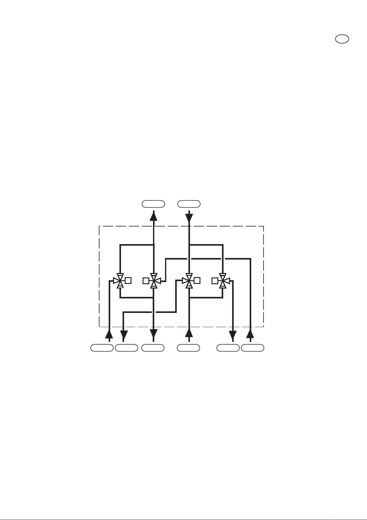
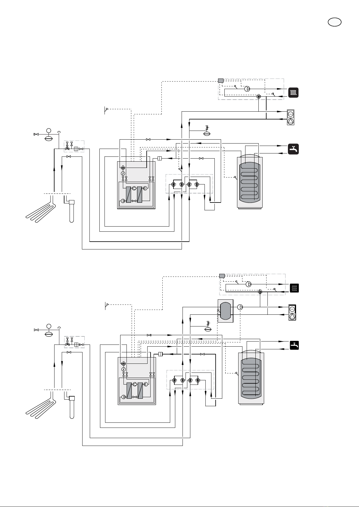
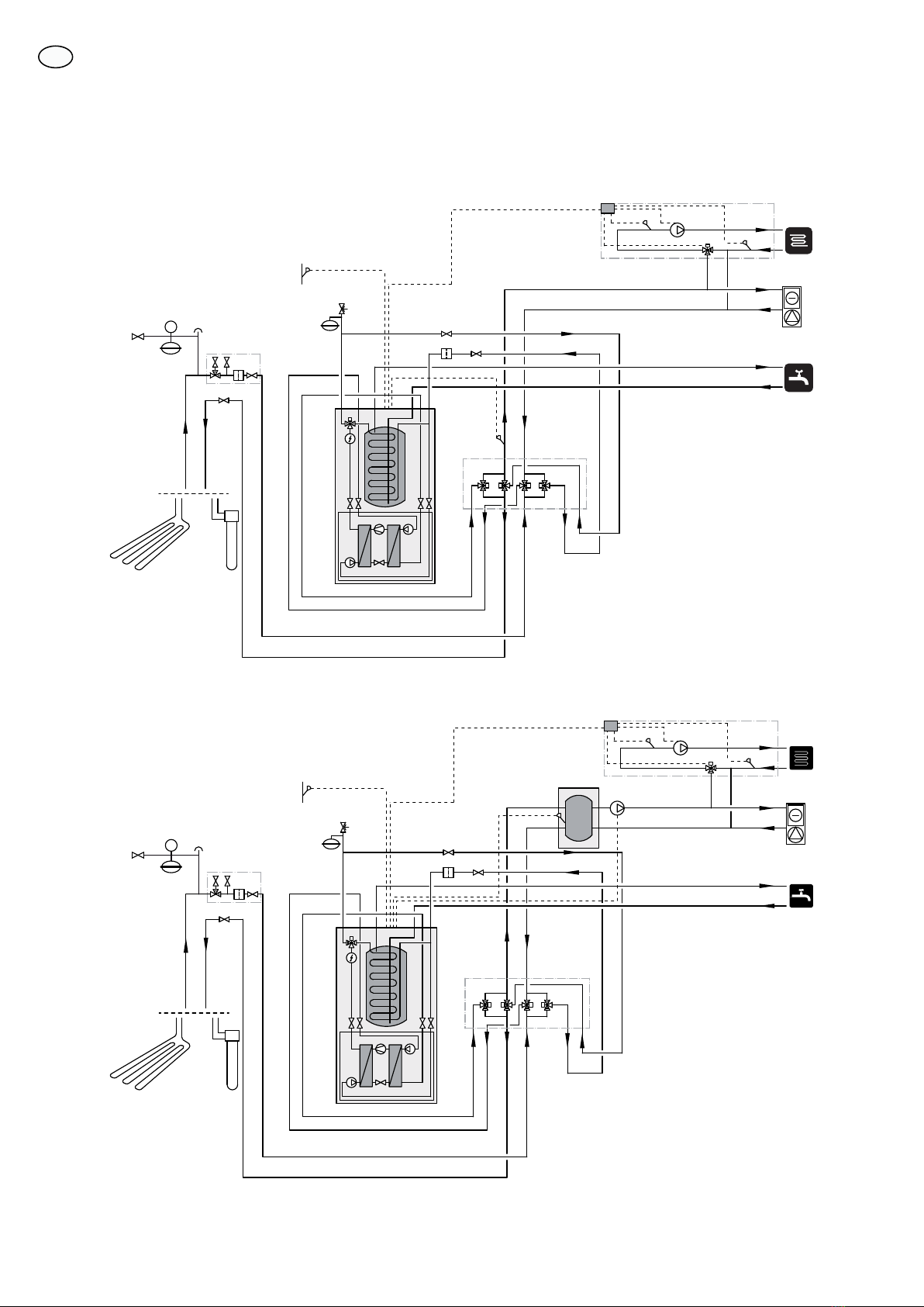
Pipe connection, the building’s climate sy-
stem
Connect the heat pump to HPAC 40 and, where applic-
able, hot water heating.
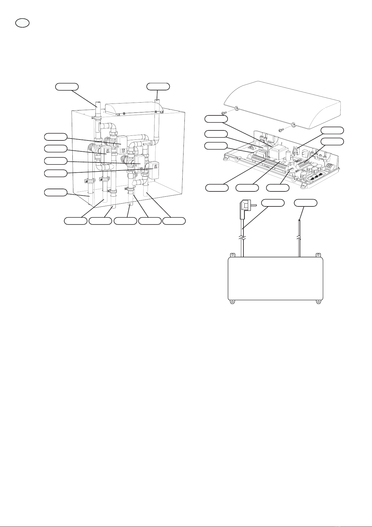
Pipe connections are made at the bottom and top of
HPAC 40. All required safety devices, shut-off valves (in-
stalled as close to the cooling module as possible), and
particle filter (supplied with the heat pump) are to be fit-
ted in such a way that HPAC 40 is also protected.
If HPAC 40 is connected to a system with thermostats on
all convectors, a bypass valve must be fitted, or a thermo-
stat must be removed to ensure sufficient flow.
Pipe connection, collector side
The length of the collector hose varies depending on the
rock /surface soil conditions and on the climate system.
Ensure the collector hose rises constantly towards the
heat pump to avoid air pockets. If this is not possible,
airvents should be used.
The climate system must be supplied with two pressure
expansion vessels.
All the system's pipes must be condensation insulated
except the pipes to the water heater.
If the temperature of the brine system can fall below 0
°C this must be protected against freezing through the
mixture of propylene glycol (NOTE! Not ethanol). The
mixing ratio should be approximately 25 % propylene
glycol and the remainder water. As a guideline for the
volume calculation, use 1 litre of ready mixed brine per
meter of collector hose, (for 40 x 2.4 PN 6.3 PEM hose).
The installation should be marked with the antifreeze
used.
Install shut off valves as close to the heat pump as pos-
sible. Fit a particle filter to the incoming pipe.
In the case of connection to an open groundwater system,
an intermediate frost-protected circuit must be provided,
because of the risk of dirt and freezing in the evaporator.
This requires an extra heat exchanger. In addition, the
ground water flow must be sufficiently large for all com-
ponents.
NOTE
This system solution means that the brine will
also circulate through the heating system.
Check that all component parts are designed
for the brine in question.
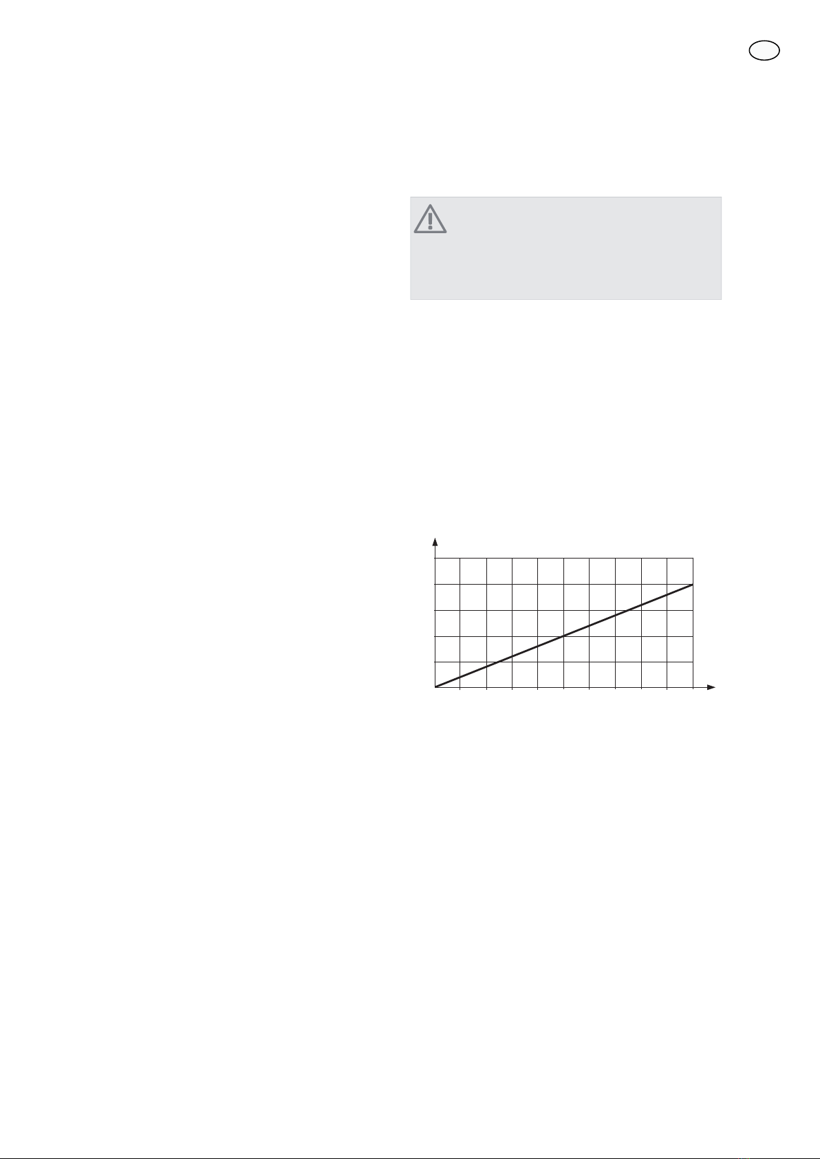
Expansion vessel
The brine circuit must be supplied with a pressure expan-
sion vessel (membrane type). If there is already a level
vessel installed this should be replaced.
The pressure expansion vessel should be dimensioned as
set out in the diagram, to prevent operating disturbances.
The pressure expansion vessel covers the temperature
range from -10 °C to +20 °C for the brine at a pre-pres-
sure of 0,5 bar and the safety valve's opening pressure
of 3 bar. The brine side must normally be pressurised to
at between 1,0 and 1,5 bar.
0
0100 200 300
10
20
30
40
50
400 500 600 700 800 900 1000
([SDQVLRQ YHVVHO
%ULQH YROXPH
Condensation insulation
Pipes and other cold surfaces must be insulated with dif-
fusion-proof material to prevent condensation.
Where the system may be operated at low temperatures,
any convection fan used must be fitted with a drip tray
and drain connection.
21
GB

Pressure drop diagram
for HPAC 40 (25 % propylene glycol, 5 °C)
Tryckfall
kPa
Flöde
l/s
0,0
5,0
10,0
15,0
20,0
25,0
30,0
0 0,1 0,2 0,3 0,4 0,5 0,6 0,7 0,8
A
B
C
D
E
A: Passiv kyla
B: Aktiv kyla, köldbärarkrets
C: Värme, köldbärarkrets
D: Aktiv kyla, värmebärarkrets
E: Värme, värmebärarkrets
3UHVVXUH GURS
)ORZ
$ 3DVVLYH FRROLQJ
% $FWLYH FRROLQJ EULQH FLUFXLW
& +HDW EULQH FLUFXLW
' $FWLYH FRROLQJ KHDWLQJ FLUFXLW
( +HDW KHDWLQJ FLUFXLW
Outline diagram
General
In cases where the system volume in the climate system
is below 20 l/kW (heat pump output at 7/45 °C) and/or
the flow in the climate system is choked uncontrolled, a
UKV tank is installed as a volume and flow increaser.
Explanation
Heat pumpEB100
Temperature sensor, outdoorBT1
Temperature sensor, hot waterBT6
Particle filterHQ1
Climate system 2 (ECS 40/ECS 41)EP21
Accessory cardAA5
Flow temperature sensor, extra climate sy-
stem
BT2
Return line sensor, extra climate systemBT3
Circulation pump, extra climate systemGP20
Shunt valveQN11
HPAC 40EQ1
Miscellane-
ous
Manometer, brineBP6
Temperature sensor, external flow lineBT25
Expansion vesselCM1
Expansion vessel, brineCM3
Accumulator tank with hot water coilCP1
Buffer vessel (UKV)CP5
CollectorEP12
Fan convectorsEP13
Safety valve, heating mediumFL2
External circulation pump, climate systemGP13
Filler valve, brineQM12
Vent valve, brineQM21
Shut-off valve, heating medium flowQM31
Shut off valve, heating medium returnQM32
Shut off valve, brine returnQM34
Filling set, brineXL15
Designations in component locations according to
standard IEC 81346-1 and 81346-2.
22
GB

Outline diagram F1145 with HPAC 40
-QM31
-FL2
-QM32
-EB100-HQ1
-CM1
-EB100-BT1
-EB100
F1145
-QM34
-XL15
-CM3
P
-BP6
-QM21
-QM12
-EP13
-BT6
-EB100
-CP1
-EP12
-GP20
-BT3
-BT2
-QN11
-EP21
-EQ1
-BT25
Outline diagram F1145 with HPAC 40 and UKV
-QM31
-FL2
-QM32
-EB100-HQ1
-CM1
-EB100-BT1
-EB100
F1145
-QM34
-XL15
-CM3
P
-BP6
-QM21
-QM12
-EP13
-BT6
-EB100
-CP1
-EP12
-GP20
-BT3
-BT2
-QN11
-EP21
-GP13
-CP5
-BT25
-EQ1
23
GB

Outline diagram F1245 with HPAC 40
-EB100-BT1
-QM31
-QM32
-EB100-HQ1
F1245
-EB100
-FL2
-CM1
-QM34
-XL15
-CM3
P
-BP6
-QM21
-QM12
-GP20
-BT3
-BT25
-BT2
-QN11
-EP21
-EQ1
-EP12
-EP13
Outline diagram F1245 with HPAC 40 and UKV
-EB100-BT1
-QM31
-QM32
-EB100-HQ1
F1245
-EB100
-FL2
-CM1
-QM34
-XL15
-CM3
P
-BP6
-QM21
-QM12
-EP13
-GP20
-GP13
-BT3
-BT2
-QN11
-EP21
-CP5
-BT25
-EQ1
-EP12
24
GB

Electrical connection
NOTE
All electrical connections must be carried out by
an authorised electrician.
Electrical installation and wiring must be carried
out in accordance with the stipulations in force.
F1145/F1245 must not be powered when in-
stalling HPAC 40.
NOTE
If the supply cable is damaged, only NIBE, its
service representative or similar authorised per-
son may replace it to prevent any danger and
damage.
NOTE
To prevent interference in the event of any spli-
cing, communication and/or sensor cables to
external connections must not be laid closer than
20 cm from high voltage cables.
The electrical circuit diagram is at the end of these install-
ation instructions.
Connecting the supply
HPAC 40 is factory fitted with power cable and plug
(W101, length 3,0 metres).
Connecting communication
This accessory contains an accessories card (AA5) that
must be connected directly to the heat pump on the input
card (terminal block AA3-X4).
If several accessories are to be connected or are already
installed, the following instructions must be followed.
The first accessory card must be connected directly to the
heat pump's terminal block AA3-X4. The following cards
must be connected in series with the previous card.
The communication cable (W102, length 2,5 metres) is
factory fitted and connected according to the table below.
Another accesso-
ry card (AA5-X4)
Heat pump
(AA3-X4)
Colour
415White (A)
514Brown (B)
613Green (GND)
1
2
3
4
5
6
7
8
AA5-X4
15
A
B
GND
A
B
GND
A
B
GND
A
B
GND
A
B
GND
14
13
AA3-X4
1
2
3
4
5
6
7
8
AA5-X4
)
)
$$;
$FFHVVRU\ FDUG
$FFHVVRU\ FDUG
ON
12345678
-X9
-X2
24 20212223 1516171819 1011121314 567891
1
N
L
PE
PE
1
2
3
4
5
6
7
8
2
3
4
5
6
7
8
9
234
-X8
-X4
-X10
-X1
$$;
ON
12345678
-X9
-X2
24 20212223 1516171819 1011121314 567891
1
N
L
PE
PE
1
2
3
4
5
6
7
8
2
3
4
5
6
7
8
9
234
-X8
-X4
-X10
-X1
$$;
$$;
(%
25
GB

Caution
The relay outputs on the accessory card can have
a max load of 2 A (230 V) in total.
Connection of sensors and external blocking
Use cable type LiYY, EKKX or similar.
External blocking
A contact (NO) can be connected to AA5-X2:23-24 to
block cooling operation. When the contact closes, cooling
operation is blocked.
24 20212223 171819
+3$&
([WHUQDO
$$;
([WHUQDO EORFNLQJ
$$;
ON
12345678
-X9
-X2
24 20212223 1516171819 1011121314 567891
1
N
L
PE
PE
1
2
3
4
5
6
7
8
2
3
4
5
6
7
8
9
234
-X8
-X4
-X10
-X1
External flow temperature sensor (BT25)
Connect the flow temperature sensor to AA3-X6:5-6 on
the input card in the heat pump.
If an external heat source or buffer vessel (UKV) is to be
used, the external flow temperature sensor (BT25) must
be installed according to the outline diagram.
The sensor has controlling functions for cooling and
heating.
NOTE
The sensor has controlling functions for cooling
and heating.
AA3-X6
1
2
3
4
5
6
7
8
9
BT25
BT25
$$;
F1245
123456789
BT25
%7
$$;
$$;
F1145
Connection of the circulation pump (GP13)
An external circulation pump (GP13) for the climate sys-
tem can, if necessary, be connected to HPAC 40.
Connect the circulation pump (GP13) to AA5-X9:8 (230
V), AA5-X9:7 (N) and X21:5 (PE).
1
2
3
4
5
6
7
8
9
L
N
PE
+3$& ([WHUQDO
$$;
;
*3
ON
12345678
-X9
-X2
24 20212223 1516171819 1011121314 567891
1
N
L
PE
PE
1
2
3
4
5
6
7
8
2
3
4
5
6
7
8
9
234
-X8
-X4
-X10
-X1
$$;
26
GB

DIP switch
The DIP switch on the accessory card must be set as fol-
lows.
ON
12345678
ON
12345678
-X9
-X2
24 20212223 1516171819 1011121314 567891
1
N
L
PE
PE
1
2
3
4
5
6
7
8
2
3
4
5
6
7
8
9
234
-X8
-X4
-X10
-X1
$$6
Relay output for cooling mode indication
It is possible to have an external indication of the cooling
mode through relay function via a potential free variable
relay (max 2 A) on the input circuit board (AA3), terminal
block X7.
If cooling mode indication is connected to terminal block
X7 it must be selected in menu 5.4, see
Program settings
Program setting of HPAC 40 can be performed via the
start guide or directly in the menu system in NIBE
F1145/F1245.
Caution
Also see the Installer manual for F1145/F1245.
Start guide
The start guide appears upon first start-up after heat
pump installation, but is also found in menu 5.7.
Menu system
If you do not make all settings via the start guide or need
to change any of the settings, this can be done in the
menu system.
Menu 5.2 - system settings
Activating/deactivating of accessories.
Select: "HPAC"
Menu 1.9.5 - cooling settings
Setting the minimum flow temperature, time between
cooling and heating, mixing valve settings as well as se-
lection of which room sensor is to control cooling.
27
GB

Technical data
Dimensions
45
165
120
380
165
65
600
400
100
515
75
655
100100 120 80 100
28
GB

Technical specifications
515(mm)Height
600(mm)Width
380(mm)Depth
5-17(kW)Intended for heat pumps
R25 (1”)(mm)Pipe connections
40(kg)Weight
29
GB
Other manuals for HPAC 40
3
Table of contents
Other Nibe Freezer manuals
Popular Freezer manuals by other brands

Zanussi Electrolux
Zanussi Electrolux ZEUC 0545 Instruction book

Electrolux
Electrolux EN3854MFX user manual

NEW POL
NEW POL XV120EL Instructions for installation, maintenance and use

Continental Refrigerator
Continental Refrigerator DLUCF27-SS Specification sheet

AEG
AEG SCS6181LNS user manual

Zanussi Electrolux
Zanussi Electrolux ZEUC 2120 Instruction booklet