Röranslutning
Allmänt
OBS!
För att undvika kondensbildning måste rörled-
ningar och övriga kalla ytor isoleras med diffu-
sionstätt material. Vid stort kylbehov krävs
fläktkonvektor med droppskål och avloppsanslut-
ning.
Köldbärarkretsen skall förses med tryckexpansionskärl.
Eventuellt befintligt nivåkärl byts ut.
Tryckexpansionskärl
Köldbärarkretsen ska förses med tryckexpansionskärl (av
membrantyp). Eventuellt befintligt nivåkärl byts ut.
Tryckexpansionskärlet bör dimensioneras enligt diagram,
för att undvika driftstörningar. Tryckexpansionskärlet
täcker temperaturområdet från -10 °C till +20 °C vid
förtrycket 0,5 bar och säkerhetsventilens öppningstryck
3 bar. Köldbärarsidan skall normalt trycksättas till mellan
1,0 och 1,5 bar.
0
0100 200 300
10
20
30
40
50
400 500 600 700 800 900 1000
7U\FNH[SDQVLRQVN¦UO
.¸OGE¦UDUYRO\P
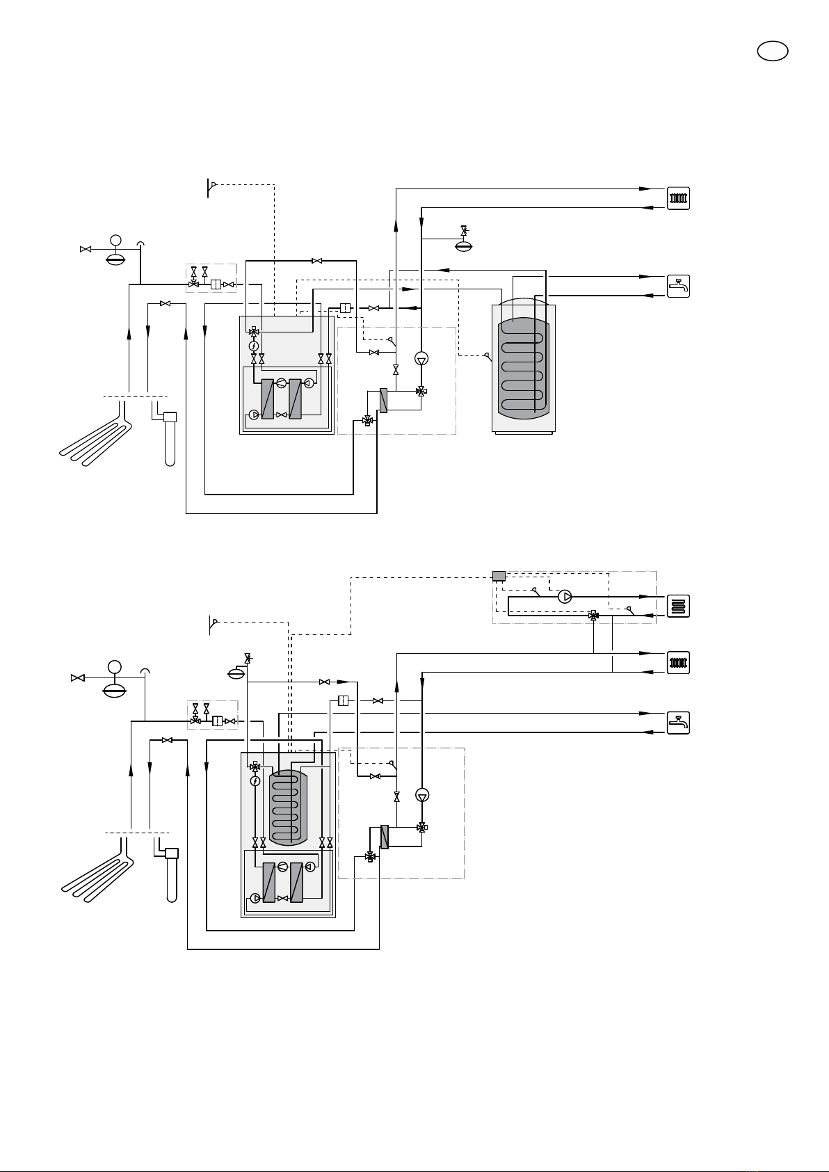
Principschema
Förklaring
VärmepumpEB100
Temperaturgivare, utomhusBT1
Temperaturgivare, varmvattenBT6
SmutsfilterHQ1
Klimatsystem 2 (ECS 40/ECS 41)EP21
TillbehörskortAA5
Framledningsgivare, extra klimatsystemBT2
Returledningsgivare, extra klimatsystemBT3
Cirkulationspump, extra klimatsystemGP20
ShuntventilQN11
PCM 40/42EQ1
Temperaturgivare, extern framledningBT25
Värmeväxlare, kylaEP6
Cirkulationspump, kylaGP13
Växelventil, kyla/värmeQN12
Shuntventil, kylaQN18
BackventilRM1
BackventilRM2
Övrigt
Manometer, köldbärareBP6
ExpansionskärlCM1
Expansionskärl, köldbärareCM3
Ackumulatortank med varmvattenslingaCP1
KollektorEP12
Säkerhetsventil, värmebärareFL2
Påfyllningsventil, köldbärareQM12
Avluftningsventil, köldbärareQM21
Avstängningsventil, värmebärare framQM31
Avstängningsventil, värmebärare returQM32
Avstängningsventil, köldbärare returQM34
Påfyllnadsventilsats, köldbärareXL15
Beteckningar i komponentplacering enligt standard IEC
81346-1 och 81346-2.
6
SE